UNiKA NP-3000 Professional Power Amplifier User Manual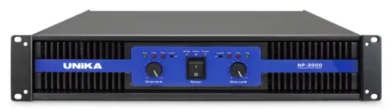
![]() Intended to alert the user to the presence of uninsulated “dangerous voltage” within the product’s enclosure that may be of sufficient magnitude to constitute a risk of electric shock to persons
Intended to alert the user to the presence of uninsulated “dangerous voltage” within the product’s enclosure that may be of sufficient magnitude to constitute a risk of electric shock to persons
![]() Intended to alert the user of the presence of important operating and maintenance (servicing) instructions in the literature accompanying the product.
Intended to alert the user of the presence of important operating and maintenance (servicing) instructions in the literature accompanying the product.
CAUTION: Risk of electrical shock -DO NOT OPEN
CAUTION: To reduce the risk of electric shock, do not remove cover. No user serviceable parts inside
Refer servicing to qualified service personnel.
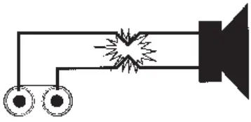
WARNING: To prevent electrical shock or fire hazard, do not expose this appliance to rain or moisture.
Before using this appliance, read the operating guide for further warnings.
![]() WARNING!
WARNING!
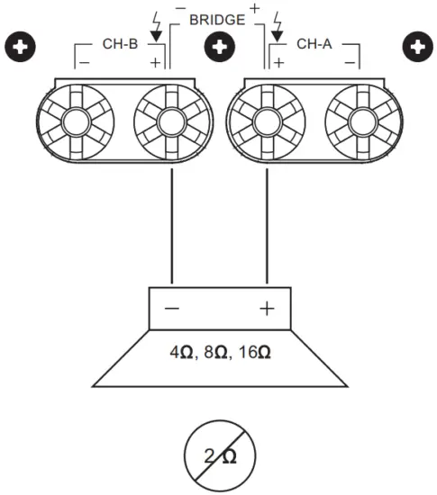
For optimun performance and reliability DO NOT PRESENT THE AMPLIFIER WITH A SPEAKER LOAD OF LESS THAN 2 OHMS. OR A COMBINATION OF SPEAKERS THAT TOGETHER ARE LESS THAN 2 OHMS!
Using one speaker, it must be rated at 2 ohms minimum.
Using two speakers, they must be rated each at 4 ohms minimum.
Using three speakers, they must be rated each at 8 ohms minimum.
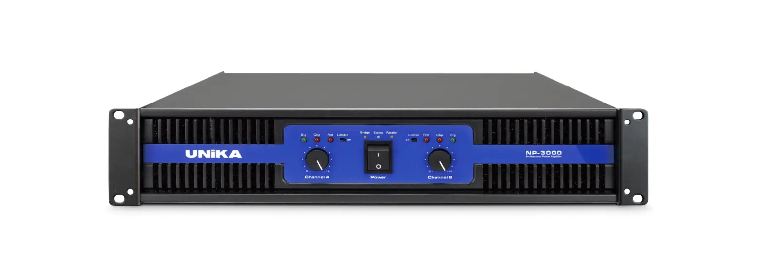
Product Overview
Front View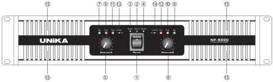
- POWER SWITCH
- STEREO INDICATOR
- BRIDGE INDICATOR LED
- PARALLEL INDICATOR LED
- GAIN CONTROL (CHANNEL A)
- GAIN CONTROL (CHANNEL B)
- SIGNAL INDICATOR LED (CHANNEL A)
- SIGNAL INDICATOR LED (CHANNEL B)
- CLIP INDICATOR LED (CHANNEL A)
- CLIP INDICATOR LED (CHANNEL B)
- PROTECT INDICATOR LED (CHANNEL A)
- PROTECT INDICATOR LED (CHANNEL B)
- LIMITER SWITCH (CHANNEL A)
- LIMITER SWITCH (CHANNEL B)
- COOLING VENTS
Back View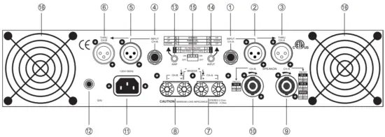
- TRS INPUT (CHANNEL A)
- XLR INPUT (CHANNEL A)
- THRU OUTPUT (CHANNEL A)
- TRS INPUT (CHANNEL B)
- XLR INPUT (CHANNEL B)
- THRU OUTPUT (CHANNEL B)
- BINDING POST OUTPUT (CHANNEL A)
- BINDING POST OUTPUT (CHANNEL B)
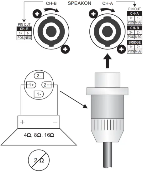
- SPEAKON OUTPUT (CHANNEL A)
- SPEAKON OUTPUT (CHANNEL B)
- AC POWER INLET CONNECTOR
- POWER RESET
- AMP MODE SWITCH
- INPUT MODE SWITCH
- LOW CUT FUNCTION SWITCH
- FAN & FILTER COVER
Inputs
Two input connectors, XLR jack and 6.3mm(1/4″) TRS jack for both balance/unbalance.
THRU
Plug the signal source outputs into first amplifier’s input, patch from the amplifier’s thru jacks to the next amplifier’s input, and so on, raising- chaining as many amplifier’s as there is no exccessive level loss.
OUTPUT
Strip back insulation 13-mm. insert wire fully, tighten barrel.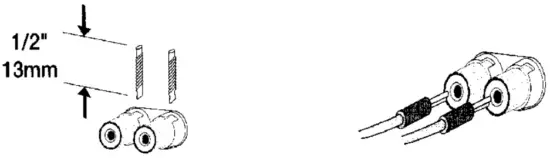
Clip Limiter
WHAT IT IS
When the audio signal drives the Amp’s output circuit beyond its power capability, it clips, flattening the peaks of the waveform. The clip limiter detects this and reduces the gain to minimize the amount of overdrive. To preserve as much of the program dynamics as possible, limiting reduces the average program level until peaks barely clip. Each channel has its own clip limiter, and you can switch it on or off independently, as shown at front panel.
WHEN TO USE IT (OR NOT)
When driving full-range speakers, clip limiting reduces high frequency distortion caused by bass overloads. It also protects higher frequency drivers from excess overdrive and harsh clipping harmonics. When driving subwoofers, some users let the amplifier clip without limiting because it gives extra “punch” to kick drums and similar sounds.
CAUTION: In bi-amp systems excessive limiting will affect the frequency balance.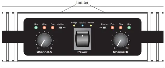
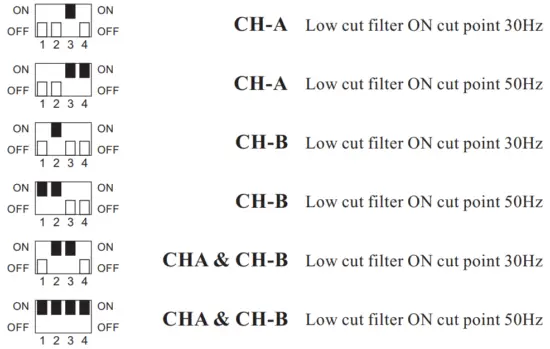
Input filter
WHAT IT IS
The low-frequency (LF) Filter rolls signals below either 30Hz or 50Hz. This improves bass performance by limiting sub-audio cone motion, making more power available for the speaker’s rated frequency range. The filter settings for each channel are controlled individual through the DIP switch settings shown. When the filter is turned off, a 5Hz roll off protects against DC or deep sub-audio inputs
WHEN TO USE IT (OR NOT)
As a rule, your speakers will sound better with proper filtering. Unless you already have filtering in a preceding device, match the setting to the low frequency rating of your speakers. Vented (bass reflex, ported, etc.) speakers are especially sensitive to cone over-excursion at frequencies below their rated limit. The 50Hz filter works well with most compact full-rage speakers, and has a slight boost at 100Hz for greater fullness. The 30Hz filter is intended for subwoofers and large full-range cabinets.
The “off” position should be used only for applications such as studio playback monitoring, where you need to know if there are unwanted sub-audio signals present in your mix.
DIP Switch settings
Parallel input mode
WHAT IT IS
“Parallel input” switches let you operate the amplifier in parallel mode, delivering the same signalto both channels without using a Y-cable. Each channel drives its own speaker load, with independent gain, filtering, and clip limiting. Set amp switch “Up”, input switch “Down”. With the inputs in parallel, and only one input signal, you can use the other set of input connectors to carry the signal to other amps.
This is called “THRU” .
WHEN TO USE IT
Parallel the inputs when driving two speakers with one input signal (parallel mode) while keeping separate Control of both channel’s gain, filtering, and limiting.
NOTE: If you are using a balanced signal , use only balanced patch cables; even one unbalanced cable will unbalance the entire signal chain, possibly causing hum.
NOTE: Turn off the “parallel input” switches when feeding the amp two separate signals.
Parallel mono mode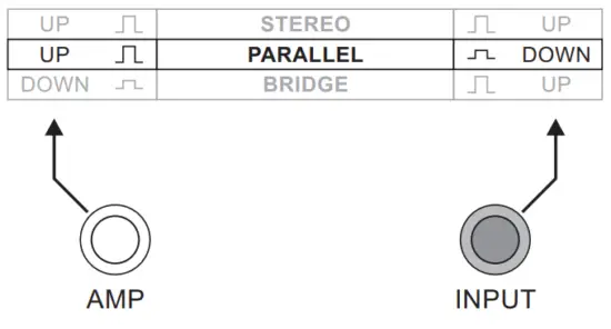

Bridge mono mode
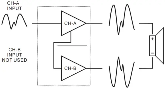
WHAT IT IS
Bridged mono combines the power of both amp channels channel into one speaker, resulting in twice the voltage swing, four times the peak power, and approximately three times the sustained power of a single channel. This mode uses channel A’s input, gain control, input filter, and clip limiter, Channel B’s should not be used.
WHEN TO USE IT (OR NOT)
Use bridged mono to deliver the power of both channels to a single 8-or 4- Ohm load. Set amp switch “Down”, Set input switch “Up”
BRIDGED-MONO PRECAUTIONS: This mode outs a high demand on the amplifier and speaker. Excessive clipping may cause protective muting or speaker damage. Be sure the speaker has a sufficient power rating.
Bridge mono mode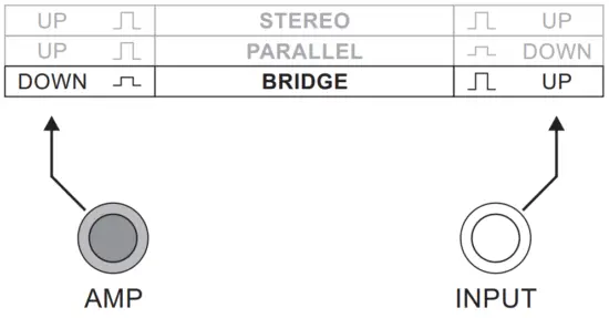
Precaution
If the load is 4 Ohms or less and prolonged overloads occur, the amplifier will probably mute for several seconds during peaks, and the circuit Breaker may trip. Do not use 2 Ohm loads.
STEREO MODE
This is the “normal” way of using the amplifier, in which each channel is fully independent. Separate signals connect at the inputs, ithe gain knobs control their respective channels, and separate speakers connect to each output. Set amp switch “UP”, Input Switch “UP”.
Bridge mono mode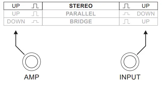
STEREO, BI-AMP, 2-CHANNEL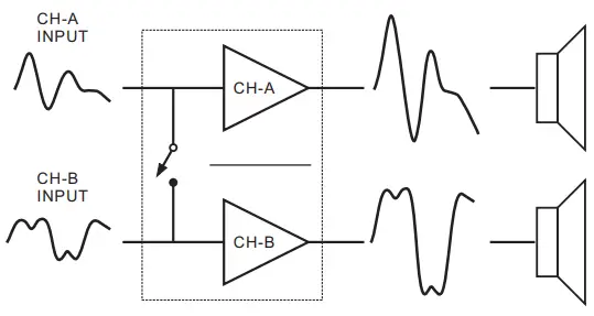
PROTECTION
- TURN-ON / TURN-OFF MUTING
The amplifier output are muted for couple of seconds after turn-on,and immediately at turn-off - SHORT CIRCUIT PROTECTION:
The output short circuit protects the output devices from short circuits and stressful loads.
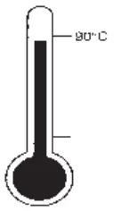
- THERMAL PROTECTION:
Dual 2-speed fans provide adequate cooling airflow. But if the heat sink temperature should climb above 90 c, the output will mute until the amplifier cools down.
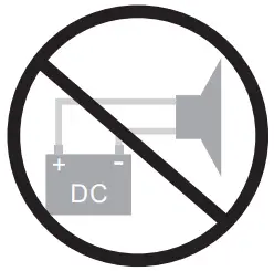
- DC FAULT
The outputs will mute if dc or excessive subsonic energy appears at them.
- INPUT / OUTPUT PROTECTION:
The input circuits are insulated by 10K Resistors. An ultrasonic network decouples RF from the output and helps keep the amplifier stable with reactive loads.
SPECIFICATIONS
| MODEL NO. | NP-3000 | NP-4500 | NP-6000 | NP-8000 |
| R.M.S. Output Power 2 CH Driven 2ohms/4ohms/8ohms 1KHz 1% THD | 2ohms 570W | 2ohms 1050W | 2ohms 1100W | 2ohms 1460W |
| 4ohms 490W | 4ohms 725W | 4ohms 960W | 4ohms 1280W | |
| 8ohms 300W | 8ohms 450W | 8ohms 600W | 8ohms 800W | |
| R.M.S. Output Power Bridged Mono 4ohms/8ohms 1KHz 1% THD | 1140W/980W | 2100W/1450W | 2200W/1920W | 2920W/2560W |
| Input Sensitivity | 0.775V | 0.775V | 0.775V | 0.775V |
| Frequency Response (20Hz~20KHz) | ±0.2dB | ±0.2dB | ±0.2dB | ±0.2dB |
| Total Harmonic Distortion | <0.02% | <0.01% | <0.01% | <0.025% |
| Crosstalk @ 1KHz | >70dB | >70dB | >70dB | >60dB |
| Damping Factor | >500 | >500 | >560 | >600 |
| Signal To Noise Ratio below rated power 20Hz to 20KHz, A-Weighted | >100dB | >100dB | >100dB | >100dB |
| Power Consumption @ Maximum Output Power 8ohms | 650W 5.91A@110V | 990W 9A@110V | 1370W 12.45A@110V | 1900W 17.27A@110V |
| Output Circuitry | CLASS AB | CLASS AB | CLASS H | CLASS H |
| Cooling System | Dual 2-speed fa | ns and heatsinks | ||
| Dimensions (H x W x D) | 88 x 483 x 332 mm | 88 x 483 x 332 mm | 88 x 483 x 434 mm | 88 x 483 x 434 mm |
| Weight | 13.7kg | 14kg | 19.4kg | 23kg |
| Rack Space | 2U | 2U | 2U | 2U |