idataLINK ALCA 64K Multi Immobilizer Transponder Bypass Interface Module
TERMS OF USE:
Automotive Data Solutions Inc. (“ADS”) products are strictly intended for installation by Certified Technicians who are employed by a registered business specialized in the installation of auto-motive aftermarket electronics products. Prior to beginning installation of an ADS product in a vehicle, it is the Certified Technician’s responsibility to review the most current Product Guide, Install Guide and vehicle-specific notes available in Weblink®. ADS is not responsible for any damages whatsoever, including but not limited to any consequential damages, incidental damages, damages for loss of time, loss of earnings, loss of profit, commercial loss, loss of economic opportunity and the like that may or may not have resulted from the use, misuse, improper installation or operation of its products. ADS reserves itself the right to suspend any Weblink® account without notice and decline to offer technical support to non-Certified Technicians, non-compliant Certified Technicians or end users.
BEFORE INSTALLATION
- Connect module to computer
- Login to Weblink account
- Flash firmware to module (module is not preloaded with firmware)
- Use accessories accordingly (accessories are sold separately)
VEHICLE LIST – 1 OF 1
BOX CONTENTS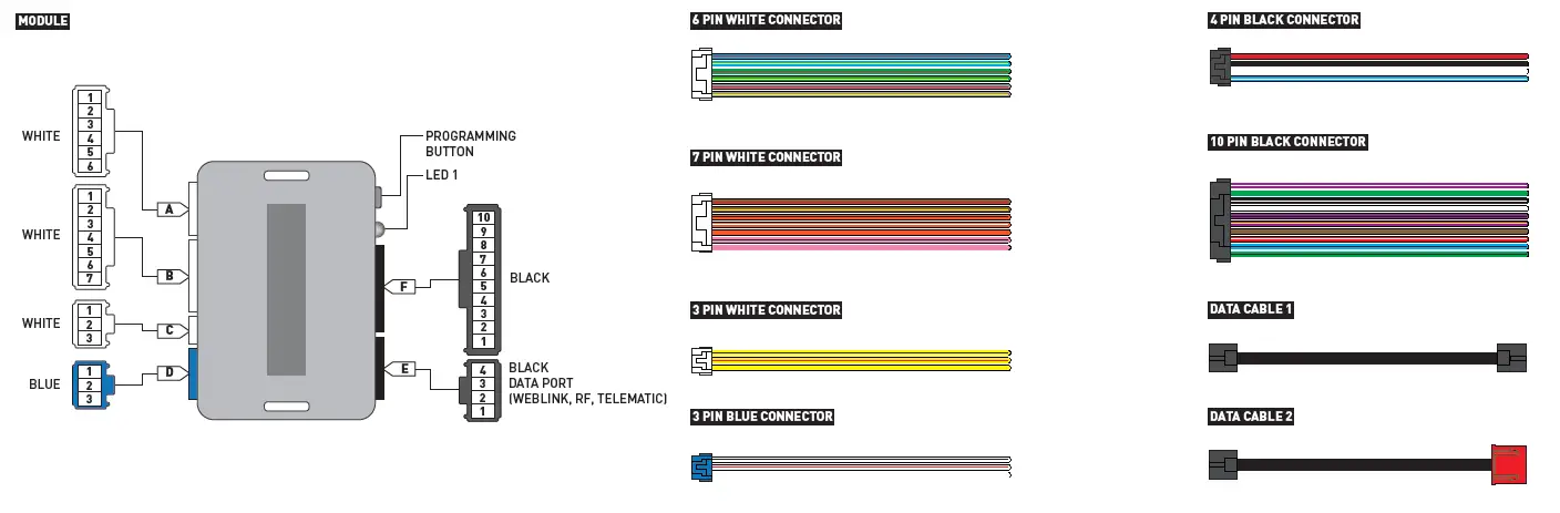

| MAKE | MODEL | YEAR | WIRE DESCRIPTION | CONNECTOR NAME | CONNECTOR COLOR | CONNECTOR TYPE | POSITION | WIRE COLOR | POLARITY | MODULE LOCATION | COMPONENT LOCATOR |
| CHRYSLER | 300 | 05-07 | Mux | C1 | Black | 5 pin | 2 | Purple/Brown | (MUX) | Ignition switch | ~ |
| Starter | C1 | Black | 5 pin | 4 | Pink/DkGreen | (+) | Ignition switch | ~ | |||
| PT Cruiser | 06-10 | Mux | C1 | Black | 5 pin | 2 | Purple/Brown | (MUX) | Ignition switch | ~ | |
| Starter | C1 | Black | 5 pin | 4 | Pink/LtBlue | (+) | Ignition switch | ~ | |||
| DODGE | Caliber with start wire | 07 | Mux | C1 | Black | 5 pin | 2 | Purple/Brown | (MUX) | Ignition switch | ~ |
| Starter | C1 | Black | 5 pin | 4 | Pink/DkGreen | (+) | Ignition switch | ~ | |||
| Charger | 06-07 | Mux | C1 | Black | 5 pin | 2 | Purple/Brown | (MUX) | Ignition switch | ~ | |
| Starter | C1 | Black | 5 pin | 4 | Pink/DkGreen | (+) | Ignition switch | ~ | |||
| Magnum | 05-07 | Mux | C1 | Black | 5 pin | 2 | Purple/Brown | (MUX) | Ignition switch | ~ | |
| Starter | C1 | Black | 5 pin | 4 | Pink/DkGreen | (+) | Ignition switch | ~ | |||
| JEEP | Commander | 06-07 | Mux | C1 | Black | 5 pin | 2 | Purple/Brown | (MUX) | Ignition switch | ~ |
| Starter | C1 | Black | 5 pin | 4 | Pink/Orange | (+) | Ignition switch | ~ | |||
| Grand Cherokee | 05-07 | Mux | C1 | Black | 5 pin | 2 | Purple/Brown | (MUX) | Ignition switch | ~ | |
| Starter | C1 | Black | 5 pin | 4 | Pink/Orange | (+) | Ignition switch | ~ |
![]()
| MAKE | MODEL | YEAR | WIRE DESCRIPTION | CONNECTOR NAME | CONNECTOR COLOR | CONNECTOR TYPE | POSITION | WIRE COLOR | POLARITY | MODULE LOCATION | COMPONENT LOCATOR |
| CHRYSLER |
200 |
11-14 | CanH | ~ | ~ | 8 pin | 6 | White/Orange | (DATA) | Ignition switch | ~ |
| CanL | ~ | ~ | 8 pin | 7 | White | (DATA) | Ignition switch | ~ | |||
| Mux | ~ | ~ | 8 pin | 1 | Purple/Brown | (MUX) | Ignition switch | ~ | |||
| Ignition | ~ | ~ | 8 pin | 3 | Pink | (+) | Ignition switch | ~ | |||
| 12V | ~ | ~ | 8 pin | 5 | Red | (+) | Ignition switch | ~ | |||
|
Aspen |
07-10 | CanH | ~ | ~ | 8 pin | 6 | White/Orange | (DATA) | Ignition switch | ~ | |
| CanL | ~ | ~ | 8 pin | 7 | White | (DATA) | Ignition switch | ~ | |||
| Mux | ~ | ~ | 8 pin | 1 | Purple/Brown | (MUX) | Ignition switch | ~ | |||
| Ignition | ~ | ~ | 8 pin | 3 | Pink/Gray | (+) | Ignition switch | ~ | |||
| 12V | ~ | ~ | 8 pin | 5 | Red | (+) | Ignition switch | ~ | |||
|
Sebring |
07-10 | CanH | ~ | ~ | 8 pin | 6 | White/Orange | (DATA) | Ignition switch | ~ | |
| CanL | ~ | ~ | 8 pin | 7 | White | (DATA) | Ignition switch | ~ | |||
| Mux | ~ | ~ | 8 pin | 1 | Purple/Brown | (MUX) | Ignition switch | ~ | |||
| Ignition | ~ | ~ | 8 pin | 3 | Pink | (+) | Ignition switch | ~ | |||
| 12V | ~ | ~ | 8 pin | 5 | Red | (+) | Ignition switch | ~ | |||
| DODGE |
Avenger |
08-14 | CanH | ~ | ~ | 8 pin | 6 | White/Orange | (DATA) | Ignition switch | ~ |
| CanL | ~ | ~ | 8 pin | 7 | White | (DATA) | Ignition switch | ~ | |||
| Mux | ~ | ~ | 8 pin | 1 | Purple/Brown | (MUX) | Ignition switch | ~ | |||
| Ignition | ~ | ~ | 8 pin | 3 | Pink | (+) | Ignition switch | ~ | |||
| 12V | ~ | ~ | 8 pin | 5 | Red | (+) | Ignition switch | ~ | |||
|
Caliber |
07-12 | CanH | ~ | ~ | 8 pin | 6 | White/Orange | (DATA) | Ignition switch | ~ | |
| CanL | ~ | ~ | 8 pin | 7 | White/Pink | (DATA) | Ignition switch | ~ | |||
| Mux | ~ | ~ | 8 pin | 1 | Purple/Brown | (MUX) | Ignition switch | ~ | |||
| Ignition | ~ | ~ | 8 pin | 3 | Pink/White | (+) | Ignition switch | ~ | |||
| 12V | ~ | ~ | 8 pin | 5 | Red/LtBlue | (+) | Ignition switch | ~ | |||
|
Durango |
07-10 | CanH | ~ | ~ | 8 pin | 6 | White/Orange | (DATA) | Ignition switch | ~ | |
| CanL | ~ | ~ | 8 pin | 7 | White/LtBlue | (DATA) | Ignition switch | ~ | |||
| Mux | ~ | ~ | 8 pin | 1 | Purple/Brown | (MUX) | Ignition switch | ~ | |||
| Ignition | ~ | ~ | 8 pin | 3 | Pink/Gray | (+) | Ignition switch | ~ | |||
| 12V | ~ | ~ | 8 pin | 5 | Red | (+) | Ignition switch | ~ | |||
|
Nitro |
07-11 | CanH | ~ | ~ | 8 pin | 6 | White/LtGreen | (DATA) | Ignition switch | ~ | |
| CanL | ~ | ~ | 8 pin | 7 | White | (DATA) | Ignition switch | ~ | |||
| Mux | ~ | ~ | 8 pin | 1 | Purple/Brown | (MUX) | Ignition switch | ~ | |||
| Ignition | ~ | ~ | 8 pin | 3 | Pink/White | (+) | Ignition switch | ~ | |||
| 12V | ~ | ~ | 8 pin | 5 | Red | (+) | Ignition switch | ~ |
| MAKE | MODEL | YEAR | WIRE DESCRIPTION | CONNECTOR NAME | CONNECTOR COLOR | CONNECTOR TYPE | POSITION | WIRE COLOR | POLARITY | MODULE LOCATION | COMPONENT LOCATOR |
| DODGE |
Ram Pickup |
07-10 | CanH | ~ | ~ | 8 pin | 6 | White/Orange | (DATA) | Ignition switch | ~ |
| CanL | ~ | ~ | 8 pin | 7 | White | (DATA) | Ignition switch | ~ | |||
| Mux | ~ | ~ | 8 pin | 1 | Purple/Brown | (MUX) | Ignition switch | ~ | |||
| Ignition | ~ | ~ | 8 pin | 3 | Pink/White | (+) | Ignition switch | ~ | |||
| 12V | ~ | ~ | 8 pin | 5 | Gray/Red | (+) | Ignition switch | ~ | |||
| JEEP |
Compass |
07-17 | CanH | ~ | ~ | 8 pin | 6 | White/Orange | (DATA) | Ignition switch | ~ |
| CanL | ~ | ~ | 8 pin | 7 | White/Pink | (DATA) | Ignition switch | ~ | |||
| Mux | ~ | ~ | 8 pin | 1 | Purple/Brown | (MUX) | Ignition switch | ~ | |||
| Ignition | ~ | ~ | 8 pin | 3 | Pink/White | (+) | Ignition switch | ~ | |||
| 12V | ~ | ~ | 8 pin | 5 | Red/LtGreen | (+) | Ignition switch | ~ | |||
|
Liberty |
08-12 | CanH | ~ | ~ | 8 pin | 6 | White/Black | (DATA) | Ignition switch | ~ | |
| CanL | ~ | ~ | 8 pin | 7 | White/Blue | (DATA) | Ignition switch | ~ | |||
| Mux | ~ | ~ | 8 pin | 1 | Purple/Brown | (MUX) | Ignition switch | ~ | |||
| Ignition | ~ | ~ | 8 pin | 3 | Pink/White | (+) | Ignition switch | ~ | |||
| 12V | ~ | ~ | 8 pin | 5 | Red | (+) | Ignition switch | ~ | |||
|
Patriot |
07-17 | CanH | ~ | ~ | 8 pin | 6 | White/Orange | (DATA) | Ignition switch | ~ | |
| CanL | ~ | ~ | 8 pin | 7 | White/Pink | (DATA) | Ignition switch | ~ | |||
| Mux | ~ | ~ | 8 pin | 1 | Purple/Brown | (MUX) | Ignition switch | ~ | |||
| Ignition | ~ | ~ | 8 pin | 3 | Pink/White | (+) | Ignition switch | ~ | |||
| 12V | ~ | ~ | 8 pin | 5 | Red/LtGreen | (+) | Ignition switch | ~ | |||
|
Wrangler JK STD Key AT |
07-18 | CanH | ~ | ~ | 8 pin | 6 | White/Black | (DATA) | Ignition switch | ~ | |
| CanL | ~ | ~ | 8 pin | 7 | White/LtBlue | (DATA) | Ignition switch | ~ | |||
| Mux | ~ | ~ | 8 pin | 1 | Purple/Brown | (MUX) | Ignition switch | ~ | |||
| Ignition | ~ | ~ | 8 pin | 3 | Pink/White | (+) | Ignition switch | ~ | |||
| 12V | ~ | ~ | 8 pin | 5 | Red | (+) | Ignition switch | ~ | |||
| RAM |
Pickup |
10 | CanH | ~ | ~ | 8 pin | 6 | White/Orange | (DATA) | Ignition switch | ~ |
| CanL | ~ | ~ | 8 pin | 7 | White | (DATA) | Ignition switch | ~ | |||
| Mux | ~ | ~ | 8 pin | 1 | Purple/Brown | (MUX) | Ignition switch | ~ | |||
| Ignition | ~ | ~ | 8 pin | 3 | Pink/White | (+) | Ignition switch | ~ | |||
| 12V | ~ | ~ | 8 pin | 5 | Gray/Red | (+) | Ignition switch | ~ |
![]()
![]()
WIRING DIAGRAM – 1 OF 1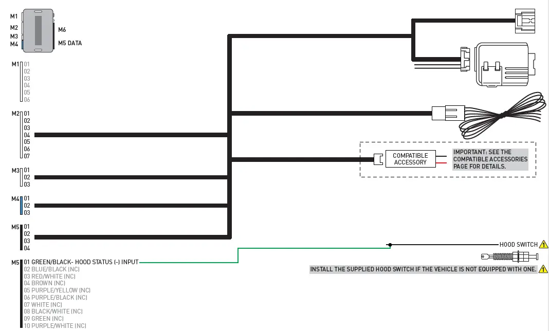

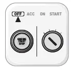
MODULE PROGRAMMING PROCEDURE – STD KEY – 1 OF 1
- Close driver door.
- Re-open driver door to wake up data bus.

- Insert key into ignition.

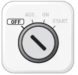
- Turn key to ON position.
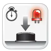
- LED will turn solid RED.

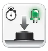
- Within 5 seconds, LED will fl ash GREEN rapidly.

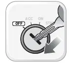
- Turn key to OFF position.
- Remove key.

- Press UNLOCK on the OEM remote. If vehicle is not equipped with OEM remote, press module programming button.

- Wait, LED will turn solid GREEN for 2 seconds.

- Module Programming Procedure completed.

NOTE:
In Valet Mode, the Remote starter is not functional. Keyless entry, Lock and Unlock will remain functional. See RF kit user manual for alternate valet mode programming.![]()
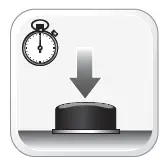
- Time restrictions. Complete next step within 7 seconds.

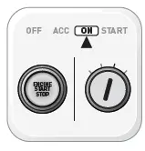
- Cycle ignition ON fi ve times [5x OFF/ON] rapidly.
- Wait, LED 1 will turn solid RED for 2 seconds.
- Set ignition to OFF position.
- Valet Mode Programming Procedure completed.

- To exit valet mode: repeat steps 1 to 5.

It is mandatory to exit the Module Navigation at the end of this procedure. Failure to exit the Module Navigation will drain vehicle battery. To exit the Module Navigation at any time: Follow STEP 13.![]()
Module must be programmed to the vehicle.![]()
Use the Module Navigation Chart on the next page.![]()
- Set ignition to OFF position.

- TO ACCESS THE MENUS: Press and hold the programming button until LED 1 turns solid GREEN.

- IN THE MENUS: Press the programming button as many times as the menu number indicates. LED 1 will fl ash GREEN an equal amount of times continuously.

- TO ACCESS THE OPTIONS: Press and hold programming button until LED 1 turns solid RED.
- IN THE OPTIONS: Press the programming button as many times as the option number indicates. LED 1 will fl ash RED an equal amount of times continuously.

- TO ACCESS THE SETTINGS: Press and hold programming button until LED 1 turns solid GREEN.
- LED 1 will flash GREEN as many times as the current (or default) setting number, continuously.

- IN THE SETTINGS: Press the programming button as many times as necessary to access your setting. LED 1 will fl ash GREEN an equal amount of times continuously.
- To return to the MENUS: exit the Module Navigation and redo the Module Navigation Procedure.

- To save and return to the OPTIONS: Press and hold programming button until LED 1 turns solid RED.

- LED 1 will fl ash RED as many times as the current option number continuously.

- Configure every other setting and proceed to step 13.

- MANDATORY: EXIT MODULE NAVIGATION. Press and hold the programming button for 7 seconds. LED 1 will fl ash RED rapidly. Release programming button. LED 1 will turn OFF.

- Module navigation completed.

- Failure to exit the Module Navigation will drain vehicle battery.

| MODULE NAVIGATION CHART: NOTES | [X] MENUS | [Y] OPTIONS | [Z] SETTINGS | |||
| I Default settings are listed in bold. II Make sure the option is covered on the vehicle before attempting to change the setting. |
01 |
CONFIGURATION | 01 | DISARM/UNLOCK BEFORE START | 01 | OFF |
| 02 | ON | |||||
| 02 | RELOCK AFTER START | 01 | OFF | |||
| 02 | ON | |||||
| 03 | RELOCK AFTER SHUTDOWN | 01 | OFF | |||
| 02 | ON | |||||
| 04 | FORCE UNLOCK ALL ON FIRST PRESS | 01 | OFF | |||
| 02 | ON | |||||
| 05 | TAKEOVER | 01 | ENABLE | |||
| 02 | DISABLE* | |||||
| 06 | SECURE TAKEOVER DELAY | 01 | 45 SEC | |||
| 02 | 90 SEC | |||||
| 03 | 03 MIN | |||||
| 04 | 04 MIN | |||||
| 07 | FACTORY KEYLESS RS SEQUENCE | 01 | DISABLE | |||
| 02 | N/A | |||||
| 03 | LOCK + UNLOCK + LOCK | |||||
| 04 | LOCK + LOCK + LOCK | |||||
|
08 |
MODULE RUN TIME | 01 | 03 MIN | |||
| 02 | 05 MIN | |||||
| 03 | 10 MIN | |||||
| 04 | 15 MIN | |||||
| 05 | 25 MIN | |||||
| 06 | 30 MIN | |||||
| 07 | 35 MIN | |||||
| 08 | 15 MIN | |||||
|
09 |
WAIT TO START DELAY | 01 | 02 SEC | |||
| 02 | 05 SEC | |||||
| 03 | 08 SEC | |||||
| 04 | 10 SEC | |||||
| 05 | 15 SEC | |||||
| 06 | 20 SEC | |||||
| 07 | 25 SEC | |||||
| 08 | 30 SEC | |||||
| 10-12 | N/A | 01 | N/A | |||
| 02-07 | Technical Support only | 01 | N/A | 01 | N/A | |
|
REMOTE STARTER ERROR CODES: NOTES | [X] NUMBER OF PARKING LIGHT FLASHES | DIAGNOSTIC |
| I WARNING: The following applies only when the parking lights are connected and supported by the system. II After a remote starter failure, the parking lights will flash [X] number times to indicate an error code. See table. | 03 | Foot brake is ON. |
| 04 | Hood is open. | |
| 05 | Engine tach signal is lost. | |
| 06 | System is in Valet Mode. | |
| 07 | Vehicle is moving (VSS). | |
| 08 | Glow plug timeout error. |
|
TEST MODULE | LED 1 STATUS | DIAGNOSTIC | |
|
I |
DURING PROGRAMMING | Flashing RED | Missing/wrong information from firmware or vehicle. |
| Solid RED | Module waiting for more vehicle information. | ||
| Flashing GREEN | Additional steps required to complete module programming. | ||
| Solid GREEN then OFF | Module correctly programmed. | ||
| OFF | No activity or module already programmed. | ||
|
II |
DURING REMOTE START | Flashing RED | Module incorrectly programmed. |
| Solid RED | Module incorrectly programmed. | ||
| Flashing GREEN | Module correctly programmed and operational. | ||
| Solid GREEN then OFF | Reset in progress. | ||
| OFF | Invalid ground when running status from remote starter. | ||
|
III |
WITH IGNITION OFF | Flashing RED | Module incorrectly programmed or connected. |
| Solid RED | Module not programmed. Waiting for more vehicle information. | ||
| Flashing GREEN | False ground when running status from remote starter. | ||
| Solid GREEN then OFF | Reset in progress. | ||
| OFF | Module at rest and ready for a remote start sequence. | ||
- Disconnect all connectors from module except the BLACK 4-PIN connector.

- Disconnect the BLACK 4-PIN connector.

- PRESS AND HOLD programming button while connecting the BLACK 4-PIN connector.
- Wait, LED 1 will flash RED. RELEASE programming button.
- LED 1 will turn RED for 2 seconds.

- Module RESET completed.

- Reconnect all connectors.

- Repeat programming procedure.

- Failure to follow procedure may result with a DTC or a CHECK ENGINE error message.

- All vehicle doors must be closed and locked prior to remote start sequence.

- Press unlock on OEM or aftermarket remote.

- Insert key into ignition.
- Turn key to ON position.

- Press and release BRAKE pedal.

- Take over procedure completed.

- Failure to follow procedure will result in vehicle engine shutdown.

| CHECKLIST | |
| 1 | WARNING: Vehicle engine will start many times. Test in a well ventilated area. |
| 2 | Close all vehicle doors, hood and trunk. |
| 3 | Press LOCK button three times [3x] rapidly on the OEM keyfob to remote start vehicle. |
| ¨ ¨ | Question 1: Does the vehicle remote start? |
| YES: Go to next step. | |
| NO: The module doesn’t detect OEM remote lock button from the vehicle communication network. Check all connections, repeat the test and call technical support, if the problem persists. | |
| 4 | Press LOCK button three times [3x] rapidly on the OEM keyfob to shut down vehicle. |
| ¨ ¨ | Question 2: Does the vehicle shut down? |
| YES: Go to next step. | |
| NO: Repeat step. If the problem persists, press on the brake pedal once [1x] to shut down the vehicle and call technical support. | |
| 5 | RAP Shutdown test |
| ¨ ¨ | Question 3: Did the radio, interior controls, and headlights turn off within 60 seconds after remote start shutdown? |
| YES: Go to next step. | |
| NO: Verify the RAP SHUTDOWN connections as illustrated in the wiring diagram. Repeat the test and call technical support, if the problem persists. | |
| 6 | Open hood. |
| 7 | If not already installed, affix the mandatory orange warning sticker under the hood and proceed to next step. |
| 8 | Press LOCK button three times [3x] rapidly on the OEM keyfob to remote start vehicle. |
| ¨ ¨ | Question 4: Does the vehicle remote start? |
| YES: The vehicle is not equipped with a factory hood pin. Install a mandatory aftermarket hood switch, then repeat the test. | |
| NO: Go to next step. | |
| 9 | Close hood. |
| 10 | Enter vehicle and close the doors. |
| 11 | Press LOCK button three times [3x] rapidly on the OEM keyfob to remote start vehicle. |
| 12 | Wait for the vehicle to start. |
| 13 | Press brake pedal. |
| ¨ ¨ | Question 5: Does the vehicle shut down? |
| YES: Go to next step. | |
| NO: The module does NOT detect the brake pedal signal. Press LOCK button three times [3x] rapidly on the OEM keyfob to shut down, check the brake connection as illustrated in the wiring diagram, if applicable, and call technical support. | |
| 14 | Exit vehicle. |
| 15 | Installation checklist completed. |


