MRU MGAprime Gas Analyzer User Guide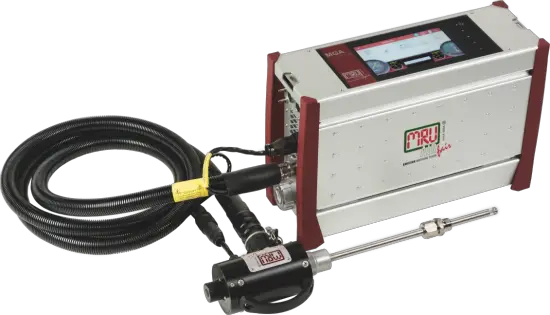
About the Quick Start Guide
This Quick-Start-Guide is intended to give you an initial overview of the analyser, its basic functions and the basic operation.
The Quick Start Guide does not replace the complete User manual of the analyser or the safety manual supplied with the analyser.
- Read and observe the separately supplied Safety manual.
- Read the complete User manual before starting the measuring operation.
- Get familiar with the analyser before using it.
USB-Stick
The complete User manual can be found on the supplied USB stick.
- Remove the cap of the USB stick.
- Insert the USB stick into your computer
 NOTE
NOTE
You can download the complete User manual directly using the following QR code.
Scan the QR Code with a QR Code Scanner.
The complete User manual will be downloaded.
Intended use
The main task of the analyser is the gas analysis for Emission control measurements on large combustion plants and engines.
- The analyser is optimized for this purpose and includes all components from the gas sampling probe to data processing.
- The analyser also performs other measurement tasks such as pressure and temperature measurement or measurement of flow velocity.
For an actual overview of the available options please visit the MRU homepage or contact our sales representatives.
Analyser, Probe, Acid Dosing Unit APE and Connectors
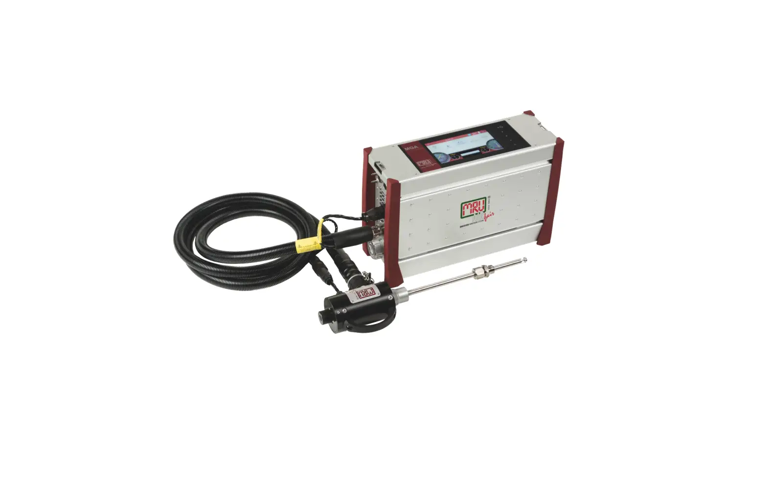
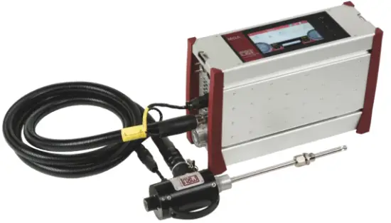
Analyser
The analyser consists of a compact and robust metal housing with shock-absorbing rubber corners. All electrical and pneumatic connections are located on the both front sides of the instrument.
It is operated exclusively via the touch-sensitive touch screen.
Probes
In combination with the analyser, probes in different versions are offered.
Heated Gas sampling probe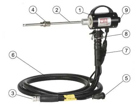
Check the probe filter before and after each measurement.
| 1 | Probe handle | 2 | Probe tube |
| 3 | Fast locking coupling | 4 | Probe cone |
| 5 | Cable plug (14-pin) | 6 | Heated hose line |
| 7 | Cable coupler (5-pin) | 8 | Fast locking coupling |
| 9 | Filter lock |
 WARNING
Danger of burns and fire hazards from Heated hose line
Injuries and burns may result.
Roll out the heated hose line completely for each measurement.
 ATTENTION
When measuring with coiled heated hose line, the hose line is destroyed due to strong heat development.
Roll out the heated hose line completely for each measurement.
Unheated Gas sampling probe
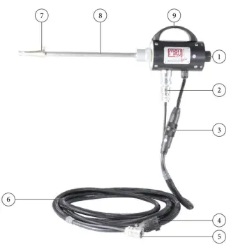
Check the probe filter before and after each measurement.
| 1 | Filter lock | 2 | Fast locking coupling |
| 3 | Cable coupler (5-pin) | 4 | Cable plug (14-pin) |
| 5 | Fast locking coupling | 6 | Unheated hose line |
| 7 | Probe cone | 8 | Probe tube |
| 9 | Probe handle |
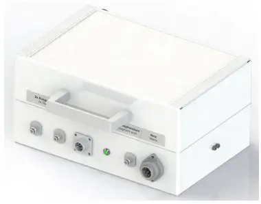
Acid Dosing Unit APE (Option)
 CAUTION
Acid from the condensate
Acid burns may result from weakly acidic liquids from the condensate.
- ► If you come into contact with acid, wash the area immediately using a lot of water.
- Note the safety data sheet for phosphoric acid (10%).
- Consider to connect a container to the condensate out port
Phosphoric acid (10 %) is injected into the analyser using the Acid Dosing Unit APE (# 12076 Injection MGAprime-Q Set). The injection of phosphoric acid (10 %) is necessary for a correct measurement.
- The injection guarantees constant conditions in the gas cooler, so that you can measure dry or humid flue gas.
- The use of phosphoric acid (10%) reduces losses of SO2, NO2 on the humid surfaces of the gas cooler.
Connectors
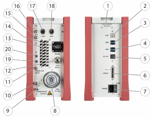
| Front side right | |||
| 1 | Loudspeaker | 2 | Ethernet (LAN) |
| 3 | USB socket | 4 | Second USB socket (option) |
| 5 | RS485 (Option) | 6 | Analog outputs 4 … 20 mA Analog-inputs 4 … 20 mA |
| 7 | Mains power supply | ||
| Front side left | |||
| 8 | Sample gas filter | 9 | Condensate outlet port Hose connection DN 4/6 |
| 10 | Sample gas outlet port (VENT) Hose connection DN 4/6 | 11 | Fresh air inlet port |
| 12 | Sample gas inlet port | 13 | Outlet fan of gas cooler |
| 14 | Probe connection, electrical | 15 | Pressure-/diff. pressure |
| 16 | Pressure-/diff. pressure (Absolute pressure) | 17 | Combustion air temperature |
| 18 | AUX socket | 19 | Connection acid injection (Option) |
| 20 | Connection acid injection (Option) | ||
Operation
Commissioning
- Connect the mains plug.
- Press Power on / off (1)
- The analyser switches on.
- The operating system boots.
- Blue LEDs for ON and power supply are switched on. (In the event of an error, the Power LED lights red)
- The device runs through a start routine of 30 minutes. The start routine includes:
- self-test
- warm-up of the NDIR bench
- cool down of the double stage gas cooler, indicated by the symbol

- Zeroing, indicated by symbol.

The remaining time until the end of zeroing is displayed. - Ready for operation after 30 min
Operation panel

All functions are controlled via the touch surface of the instrument. Different gestures are available in the individual menus and windows.
| 1 | Power-on and reset | 2 | Reserve |
| 3 | Reserve | 4 | LED display mains operation/battery charging mode |
| 5 | Reserve | 6 | Current flow rate |
| 6a | Current pump load | 7 | Current temperatures heated hose |
| 8 | Selected measuring program, e.g. Test or measurement program | 8a | APE |
| 9 | Current temperatures of NDIR bench | 10 | Current temperatures of gas cooler 1 |
| 10a | Current temperatures of gas cooler 2 | 11 | Access to detailed information on the instrument components. Especially for service or inquiry |
| 12 | Menu Sites | 13 | Menu Measure |
| 14 | Status bar: display of zero point, alarms, executed measuring pro- gram, selected fuel, heat-up-, cool-down phase | 15 | Menu Settings |
| 16 | Menu Extras | 17 | Menu Info |
| 18 | Battery Charge indicator | 19 | Context menu with window- dependent additional functions |
Measurement
ATTENTION
- Operate the analyser in a standing position only.
- See also chapter 4.4 Connectors, S.6.
- Set up and operate the analyser only as shown in the illustration.
- Never operate the analyser in a lying position.
The analyser may otherwise be damaged.
Prepare measurement
Operating temperature
The internal gas cooler operates at 4°C, which is the dew point of the sample gas to the sensors. Components along the gas line may be damaged if they are colder than 4°C and condensation appears internally.
Therefore, if the analyser has been stored very cold below 0°C, it is essential to wait for the analyser to warm up in a warm environment in order to avoid such condensation! In such cases, take a typical warm-up time for the instrument of one hour into account, especially when wet flue gases are to be measured.
If the operating temperature is not within the permissible range, a corresponding message is displayed.
Power supply
The analyser can be operated with an internal battery to warm up the instrument or to use internal instrument functions. A mains connection is required for the measurement including heated gas sampling probe and heating hose.
ATTENTION
When measuring with coiled heated hose line, the hose line is destroyed due to strong heat development.
Roll out the heated hose line completely for each measurement.
Opening the transport bag
- Open the transport bag to get access the control panel (1).
- Open the transport bag to get access to the left side. (2).
- Open the ventilation flap (3).

Connections to the analyser
See also Chapter 3 Analyser, Probe, Acid Dosing Unit APE and . S. 3.
- Connect the gas sampling probe to Sample gas inlet port (12) (gas coupling and round plug).
- Note that acidic condensate as well as phosphoric acid is discharged from the condensate out port (9). Consider to connect a hose or collecting container to the condensate outlet when appropriate. Ensure that the empty volume of the collection container is sufficient (24ml/h). The hose must not be closed and the collection container must have a ventilation opening.
- Please note that measuring gas may leak at the analyser side or at the Sample gas outlet port (10)
- Ensure that ambient fresh air can be sucked in at the Fresh air inlet port (11). Consider to connect a hose leading fresh air to analyser.
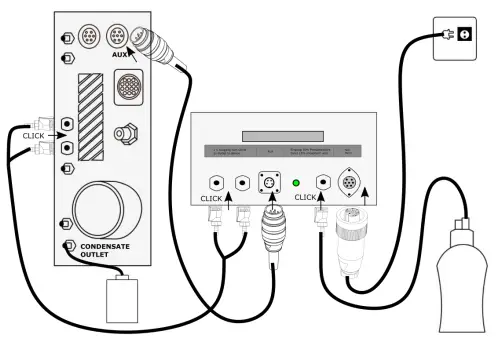
Connecting Acid Dosing Unit APE (Option)
CAUTION
Acid from the condensate
Acid burns may result from weakly acidic liquids from the condensate.
- ► If you come into contact with acid, wash the area immediately using a lot of water.
- Note the safety data sheet for phosphoric acid (10%).
- Consider to connect a container to the condensate out port
NOTE
Phosphoric acid (10%) is not included in the scope of delivery.
Phosphoric acid (10 %) must be procured by the operator.
Check the remaining contents of the acid tank before measurement.
- Connect a collection container to the condensate outlet.
- Plug the AUX-connector into the analyser. The AUX-connection cable ensures that no phosphoric acid (10 %) is injected into the analyser when the pumps are switched off.
- Plug the couplings of the connecting hose into the connection nozzle of the Acid Dosing Unit APE (2x outlet to device).
- Plug the couplings of the connecting hose into the connection nozzle of the analyser.
NOTE
You do not have to pay attention to any special arrangement of the couplings between the Acid Dosing Unit APE and the analyser.
Make sure that the hose connectors click into place audibly.
- Plug the coupling of the connecting hose to the acid tank into the connection nozzle of the Acid Dosing Unit APE (Input 10 % phosphoric acid). Plug the cable socket of the mains cable into the Acid Dosing Unit APE (Main).
- Plug the power cord into the socket.
- At the end of the zero-point measurement, phosphoric acid (10 %) will be injected.
- The control lamp lights up green as soon as phosphoric acid
(10 %) will be injected. The control of the acid dosing unit APE
begins 40 minutes after the analyser is started
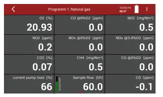
Take a measurement
- Touch the menu Measure.
- The measured value window appears.
- The measurement starts with the set parameters.