![]()
Equipment and Products for Quality Hay.’
P.O. Box 63 we 2821 Harvey Street t.e Hudson, WI 54016 800-635-7468 4s
www.harvesttec.com
Model 437T
25 Gallon Automatic Preservative Applicator
Installation Manual
Introduction
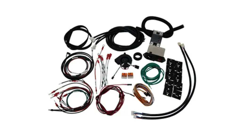
Congratulations on purchasing a Harvest Tec Model 437T applicator. This applicator is designed to apply Harvest Tec buffered propionic acid. The use of other products can cause application problems and damage to system components. The model 437T base kit includes the following parts: Tank, Frame, Pumps, Hose, Baler Mounted Processor, Touchscreen Display, Moisture Sensors, and Miscellaneous Hardware. The applicator can be installed on most round balers with the proper installation kit. Before installing the unit on the baler, make sure you have the proper installation kit. (See the chart below.) If you are unsure about your installation kit contact your dealership for specifications. For your convenience, we have included a parts breakdown for the model 437T applicator. If something goes wrong, bring this manual into the dealership so they can order the correct parts for you. Ordering the correct part number is very important. It will save you time, money, and your crop.
Installation Kit Reference Chart
| BALER MAKE | BALER MODEL | INSTALLATION KIT |
| Kuhn | VB 2160 & VB 2190 | 030-0437-SO |
Tools Needed
- Standard wrench set
- Standard socket set
- Standard screw driver or 5/16” nut driver
- Side cutter
- Hose cutter
- Crescent wrench
- Hammer
- Metal drilling and cutting tools
- Center Punch
Installation of Applicator
1. Installation of Mounting Brackets, Tank, Pump Plate, and Drain / Fill Line
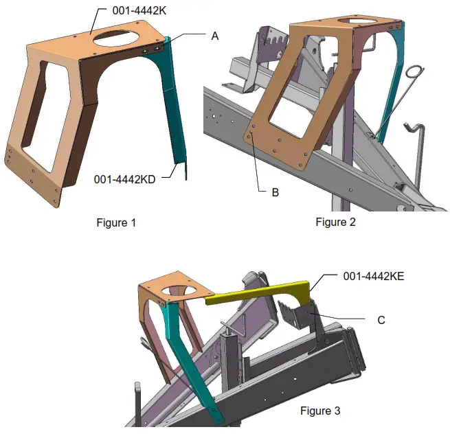
Locate tank saddle legs (001-4442K & 001-4442D) as shown in figure 1. Fasten leg 001-4442D to 001-4442K with two 3/8 x 1 1/4” bolts, locks, flats, and nuts at point A.
Secure 001-4442K to the baler using a 3/8 x 1 1/4” bolt, flat, and nut through the existing hole shown at point B on figure 2. Allow the gusset flange lip to rest on top of the aler tongue. Clamp both legs to secure the bracket to the baler and drill six 9/16” on 001-4442K and two 9/16” holes on 001-4442D, using the bracket as a guide. Secure the legs to the baler frame with eight 1/2 X 1 1/4” bolts, locks, flats, and nuts. Tighten all hardware.
Locate the legs support bracket (001-4442E). Fasten the support to the baler, in the existing holes, as shown at point C in figure 3. Use two 5/16 x 1” bolts, flats, locks, and nuts. Tighten all hardware.
Installation of Mounting Brackets, Tank, Pump Plate, and Drain / Fill Line (continued)
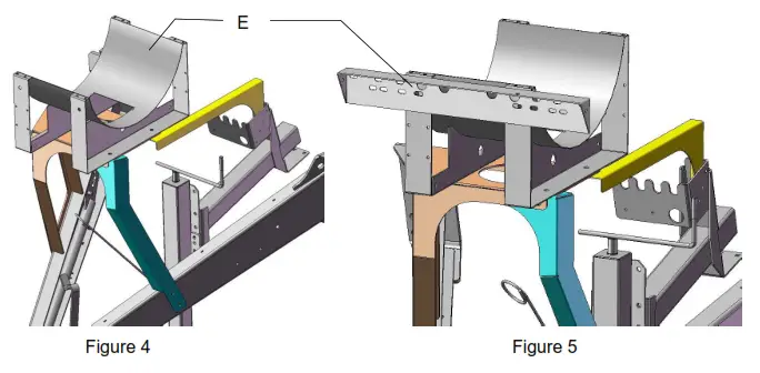
Locate the tank and saddle assembly. Position the tank and saddle so that the side tank fitting is towards the right side of the baler. The additional two weld nuts on the saddle will then be facing forward as shown in point E on figure 4. Fasten the tank saddle to the frame using four 1/2 x 1 1/4” bolts, locks, flats, and nuts. Tighten all hardware.
Locate the pump plate assembly. Remove the four flange bolts holding the two pieces of the pump plate together. Mount the pump plate mounting bracket (001-4646C) as shown below point E in figure 5. Attach the bracket to the saddle using two 3/8 x 1” bolts, locks, and flat washers. Tighten all hardware. Attach the remaining half of the pump and secure with the four 3/8 x 3/4” flange bolts.
Locate the drain/fill 3/4” hose, 3/4” elbow, 3/4” straight fitting, valve, quick coupler, and mounting bracket. Thread 3/4″ elbow fitting (#003-EL3434) into side tank fitting. Run a 3/4″ hose from the elbow down the frame to the bottom of the baler. Drill 1/4″ holes to accept the valve holder bracket and use 5/16” x 1 1/4” self-tapping screws. Connect the valve assembly to another end of the hose. Place hose clamps on both ends.
2. Placement of Spray Nozzle Assembly
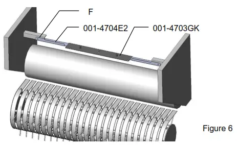
Locate the spray shield holder (001-4704E2) and spray shield (001-4703GK). Center the spray shield holder over the rotor. Clamp the bracket and drill two 7/16” holes point F on figure 6. Secure the bracket using two 3/8 x 1 1/4 bolts, locks, flats, and nuts. Tighten all hardware. Install the shield and secure using the two lynch pins (008-4576).
3. Installation of Plumbing
A. Intake
Use the 003-EL3412 on the bottom of the tank to route 1/2” line (002-9001) to the 003-A1212 fitting on the ball valve already attached to the pump plate. Attach hose clamps (003-9003) on both of the fittings.
B. Discharge
The three – 1/4″ hose assembly will be used to attach the pumps to the spray nozzles. The pump order is, from closest to the filter bowl, 1,2, and 3. Pump 1 will attach to the three main nozzles. Pump 2 will use the green hose and Pump 3 will use the blue hose to attach to the auxiliary nozzles.
C. High and Low Output Tips
Your baler comes with two sets of tips: a low setting and a high set.
- The low set will cover outputs of 32 to 440 lbs/hr or approximately 8-27 tons/hour.
Install the following tips for low output:
Clear hose to silver tips on all three connected nozzles.
Green hose to green tip.
Blue hose to red tip. - The high set will cover outputs of 84 to 632 lbs/hr or approximately 21-40 tons/hour. Install the following tips for high output:
Clear hose to white outside tips and orange middle tip.
Green hose to blue tip.
Blue hose to gray tip.
**Refer to Tip Output under APPLICATION RATE of the control unit to calibrate**
Installation of Moisture Sensing Pads
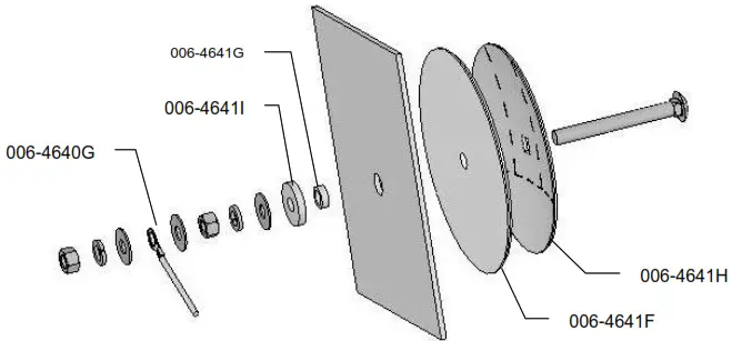
- If your baler is equipped with bale shaping pads, remove the disc and use the existing hole (may need to be drilled larger, 3/4″) to install new moisture sensing discs.
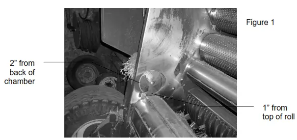
- If your baler is not equipped with bale shaping pads you will need to drill a hole in the chamber directly behind and above the starting roll (Figure 1).
- The mounting hole will be 3/4″ in diameter. Use a plastic pad (006-4641F) and place it into the baler to use as a template. The bottom edge of the pad will be placed 1” up from starting roll and 2” from the back of the bale chamber. (Figure 1)

- Locate the 006-4641G. The piece will need to be cut down to size. Use the already machined line in the bushing to cut off the small piece shown above.
- Depending on the baler the bolt may need to be trimmed for proper fit.
- Tighten all of the hardware to 50 ft/lbs.
- Make sure that the plastic pad is protecting all metal surfaces of the disc from touching the baler.
- Run the moisture wire harness (006-4640G) from the pump plate area to each disc securing it with cable ties.
- Apply silicone over nuts and washers.
5. Power Cable and Main Wiring Harness Installation
- Connect the power harness (006-4640A) to the battery (12 volts) using the red wire with fuse to the positive side and the black wire to the negative
a. The power harness must be connected to the battery! The unit will draw more amps than convenience outlets can handle. Any modifications of the power harness will void the system’s warranty. CONTACT HARVEST TEC BEFORE MODIFICATIONS.
b. This unit will not function on positive ground tractors.
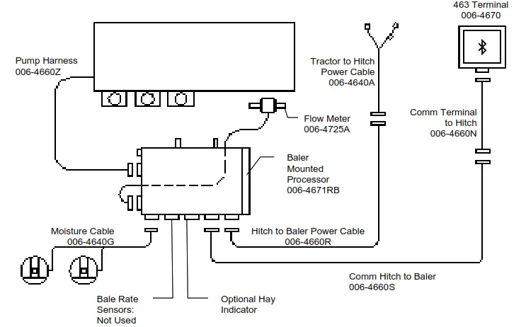
c. If the unit loses power while operating it will not keep track of accumulated pounds of product used. - The power harness (006-4640A) will run from the tractor battery to the hitch. The power harness (0064660R) will connect to the tractor power harness (006-4640A) at the hitch. Run the Communication harness (006-4660N)from the cab to the hitch. This wire will connect o the Communication harness (006-4660S). These wires ill run together to the Baler Mounted Processor (006-4671RB).
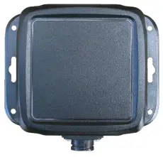
- Connect the Communication harness (006-4660N) to Bluetooth Receiver (030-4672A) mounted in the cab.
a. Mount Bluetooth Receiver (030-4672A) in a safe location as close to the iPad as possible in the cab. - Connect Flow Meter (006-4725A) and pump harness (006-4660Z) to the Baler Mounted Processor.
- Attach moisture cable (006-4640G) to Baler Mounted Processor.
- Install Baler Mounted Processor in pump plate using 5/16” lock, nut, and flat washers.
NOTE: The plugs on the Baler Mounted Processor must face down. Failure to mount correctly will void the system’s warranty.
SYSTEM WIRING DIAGRAM
Installation of the Control
Installation of Bluetooth Receiver
Locate a safe location in the cab of the tractor to place the Bluetooth Receiver (030-4672A). The recommended location is as close to the iPad being used as possible.
Connect the communication wire (006-4660N) to the bottom of the receiver.
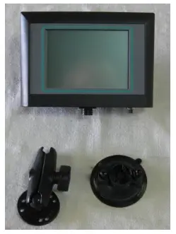
Optional Touch Screen Display
Use a suction cup mount (001-2012SCM) to position the monitor in the cab. Make sure the glass is clean before installing the suction cup mount. If an open-cabbed tractor is used, use the supplied #10 screws for installation on the fender. If the unit is mounted on a fender it will need to be removed at night and stored in a clean, dry area. Use the Ram mount (001-2012H) swivel-positioning nut to tighten the entire assembly. Adjust it so that you can view the entire screen and be able to use the touch screen without interfering with other tractor functions.
Connect the communication wire (006-4660N) to the bottom of the terminal.
Installation of Display Cable Harness
On the bottom of the touchscreen display, you will find the main display wire plug. The harness (006-4660N) will need to be attached to this plug and run through the cab towards the hitch where it will connect with its matching harness (006-4660L) from the BMP.
Maintenance
- Clean the tip strainers and main strainer every 10 hours of operation.
- Depending on the product being used, the system may need to be flushed with water at a regular intervals (consult with the manufacturer of the chemical.) If Harvest Tec product is being used, flushing is not necessary.
- Although the pump can run dry, extended operation of a dry pump will increase wear. Watch the preservative level in the tank.
- Cover the automatic cab terminal on open station tractors if left outside.
- Pump performance may start to decline after 400 hours (5000 bales on large round balers) of use. Rebuilding the pump is a simple procedure if the motor is not damaged. Order pump rebuilding kit #007-4581 for the automatic unit.
- If you are using bacterial inoculants, flush your system daily after every use.
- Clean the tank cap every 10 hours of operation.
Maintenance Schedule
| Daily | 10 hrs | 400 hrs | Weekly | Monthly | Season | |
| Diagnostics | X | X | ||||
| Filter bowl cleaning | X | X | ||||
| Tip screen cleaning | X | X | ||||
| Tank cap cleaning | X | X | ||||
| Dielectric grease connections | X | X | ||||
| Rebuild pump | X | |||||
| Battery connections | X | X | ||||
| Check valves | X | |||||
| Visually inspect hoses | X | X |
Winter Storage
- Thoroughly flush the system with water.
- Remove the filter bowl and run dry until the water has cleared out of the intake side.
- Remove the red plug from the bottom of the pump, drain, and run the pump for 30 seconds or until dry.
- Drain all lines on the outlet side.
- Never use oils or alcohol-based anti-freeze in the system.
- For spring start-up, if the pump is frozen, turn off the power immediately to avoid burning the motor out. The pump head can be disassembled and freed or rebuilt in most cases.
- Disconnect power from the system.
- Remove the display from the tractor and store in a warm, dry place.
Backup Fuse
The Model 463 is equipped with a backup system if your display is not functioning. This function is intended for use only as a temporary means for application and not as a way to apply preservatives over multiple fields or for a lengthy amount of time. The baler-mounted processor has a location for a backup fuse on the same side as the pump and flows meter harness that bypasses all other system inputs and applies preservatives using one pump (Pump Three) at a constant lbs/hour shown below. These values are based upon an input voltage of 13.5 DC. Insert at least a 10 amp up to 20 amp fuse (3 AG style) into the backup fuse port to activate the bypass. The system will not turn off or pause until the fuse is removed. The main fuse must also be functional for the backup fuse to work.
| Tip Set | Output (lbs/hour) | |
| 463 | High | 230 |
| Low | 180 |
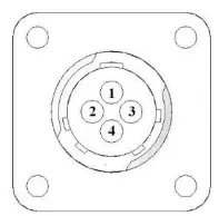
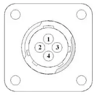
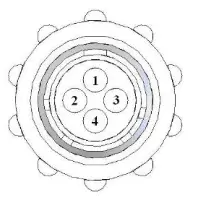
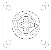
Pin Outs
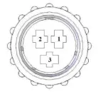
A. Main power connector mounted on the battery
| Pin 1 Pin 2 Pin 3 | Red Black Not used | + 12 V input from tractor supply Ground from tractor supply |
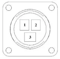
B. Main power connector mounted on BMP
| Pin 1 Pin 2 Pin 3 | Red Black Not used | + 12 V input from tractor supply Ground from tractor supply |
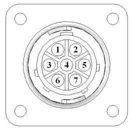
C. Pump connection colors
| Pin 1 Pin 2 Pin 3 Pin 4 Pin 5 Pin 6 Pin 7 | Black with orange markings Black with green markings Black with yellow markings Not used Orange with black markings Green with black markings Yellow with black markings | Pump 1 ground Pump 2 ground Pump 3 ground Pump 1 Positive Pump 2 Positive Pump 3 Positive |
 D. Flow meter connection on BMP
| Pin 1 Pin 2 Pin 3 Pin 4 | White Green Brown Black | 5 – 12 V (+) supply Ground Signal Shield |
E. Connector for Hay Indicator option on BMP
Note: Hay indicators are an option that will turn the system on and off automatically as hay enters the pickup of the baler.
| Pin 1 Pin 2 Pin 3 Pin 4 | Red Black White Not used | +12V Ground Signal wire |
F. Moisture connector mounted on BMP
| Pin 1 Pin 2 Pin 3 Pin 4 Pin 5 Pin 6 Pin 7 Pin 8 Pin 9 | Brown Blue Brown Blue Silver Silver Not used Not used Not used | Moisture input 1 Moisture input 2 Diagnostic 1 Diagnostic 2 Shield Shield |

G. Communication harness Bluetooth Receiver or display to hitch
| Pin 1 Pin 2 Pin 3 Pin 4 | Red Black Blue Orange | Power to display Ground to display Comm channel OH Comm channel OL |
H. Communication harness hitch to the baler-mounted processor
| Pin 1 Pin 2 Pin 3 Pin 4 | Red Black Blue Orange | Power to display Ground to display Comm channel OH Comm channel OL |
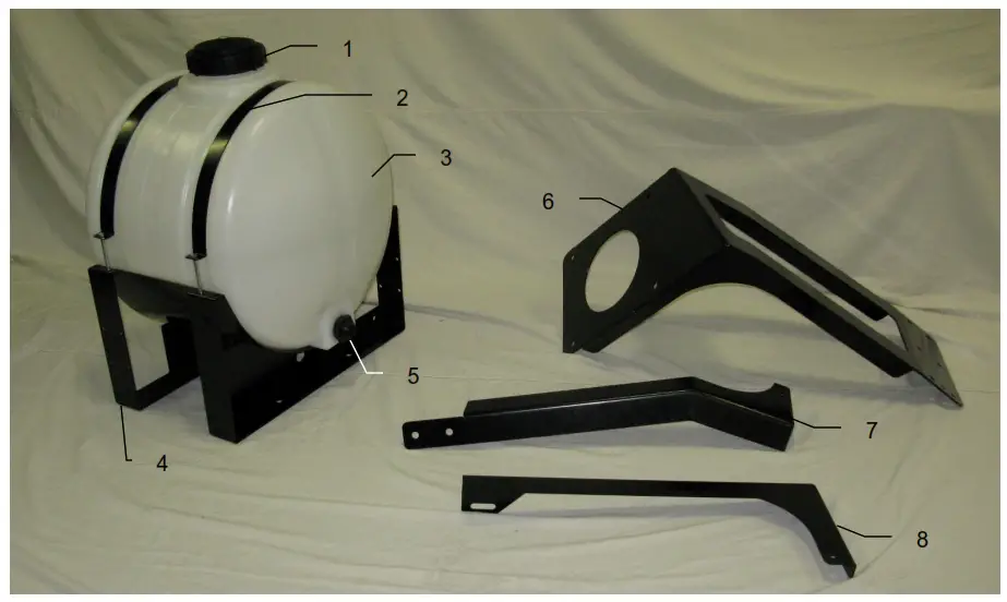
Harvest Tec Model 437 Base Kit
| Ref# | Description |
| 1 | Tank Cap |
| 2 | Tank Strap |
| 3 | Tank |
| 4 | Saddle |
| 5 | Tank Fitting |
| 6 | Tank mount bracket |
| 7 | talk support |
| 8 | Mounting support |
| Part # | Qty |
| 005-9022C | 1 |
| 005-9022CG | 1 |
| 001-4402 | 1 |
| 005-9022 | 1 |
| 001-4442 | 1 |
| 005-9100 | 1 |
| 001-4442K | 1 |
| 001-4442KD | 1 |
| 001-4442KE | 1 |
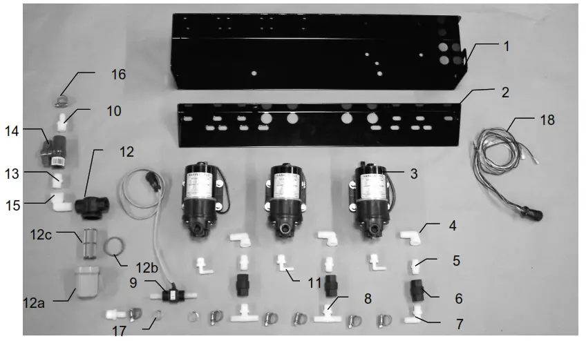
Parts Breakdown for Pump Plate
| Ref# | Description | Part# | Qty |
| 1 | Pump plate | 001-4646D | 1 |
| 2 | Mounting Bracket | 001-4646C | 1 |
| 3 | Pump | 007-4120H | 3 |
| 4 | Street elbow fitting | 003-SE38 | 3 |
| 5 | Nipple fitting | 003-M3838 | 3 |
| 6 | Check valve | 002-4566F | 3 |
| 7 | Elbow fitting | 003-EL3812 | 1 |
| 8 | Tee fitting | 003-T3812HB | 2 |
| 9 | Flow meter assembly | 006-4725A | 1 |
| 10 | Straight fitting | 003-A1212 | 2 |
| 11 | Elbow fitting | 003-JEL1238 | 3 |
| 12 | Filter bowl assembly | 002-4315-100 | 1 |
| 12a | Filter bowl only | 002-4315F | 1 |
| 12b | Filter bowl gasket | 002-4315D | 1 |
| 12c | Filter bowl screen | 002-4315A | 1 |
| 13 | Nipple fitting | 003-M1212 | 1 |
| 14 | Ball valve | 002-2212 | 1 |
| 15 | Street elbow fitting | 003-SE12 | 1 |
| 16 | Hose clamp | 003-9003 | 7 |
| 17 | Hose clamp (Flow Meter) | 003-9005 | 2 |
| 18 | Pump Cable | 006-4660Z | 1 |
| NP | Pump rebuild kit | 007-4581 | 1 |
| NP | Elbow | 003-EL1212 | 1 |
| NP | Not Pictured |
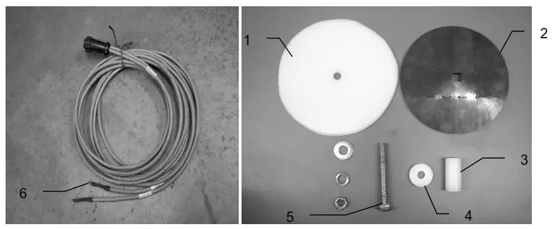
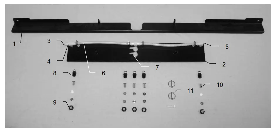
Moisture Pad, Drain / Fill and Hoses
| Ref# | Description | Part # | Qty |
| 1 | Plastic Pad | 006-4641F | 2 |
| 2 | Moisture Disc | 006-4641H | 2 |
| 3 | Plastic Bushing | 006-4641G | 2 |
| 4 | Plastic Isolator | 006-4641I | 2 |
| 5 | 1/2X4 1/2” Carriage Bolt | 006-4640G | 2 |
| 6 | Moisture Cable | 030-4643 | 1 |
| 5-Jan | Moisture Pad Assembly | 2 |
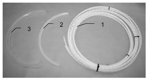
| Ref | Description |
| 1 | Triple weld hose (from pumps to tips) Hose assembly (3 hose assembly) |
| 2 | 1/2” Hose (tank to filter) |
| 3 | 3/4” hose (drain/fill line) |
| 4 | Straight fitting |
| 5 | Ball valve |
| Part# | Qty | Ref | Description | Part# | Qty |
| 002-9016 | 15ft | 6 | Valve holder | 001-6702H | 1 |
| 002-9016B | 15ft | ||||
| 002-9016G | 15ft | ||||
| 030-9016RB | 1 | 7 | Female coupler | 002-2204A | 1 |
| 002-9001 | 6ft | 8 | Male coupler | 002-2205G | 1 |
| 002-9002 | 6ft | 9 | Elbow | 003-EL3434 | 1 |
| 003-A3434 | 1 | 10 | Jiffy Clip | 008-9010 | 3 |
| 002-2200 | 1 | 11 | Hose clamp | 003-9004 | 2 |
Parts Breakdown for Control Box and Wiring Harnesses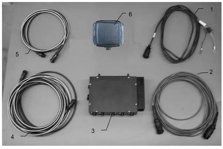
| Ref | Description | Part # | Qty |
| 1 | Power lead tractor | 006-4640A | 1 |
| 2 | Power lead baler | 006-4660R | 1 |
| 3 | Baler mounted processor | 006-4671RB | 1 |
| 4 | Communication harness (baler) | 006-4660S | 1 |
| 5 | Communication harness (tractor) | 006-4660N | 1 |
| 6 | 400 Series Bluetooth Receiver | 030-4672A | 1 |
| NP | Optional Touch Screen Display | 006-4670 |
Optional iPad Mini Mounting Kit
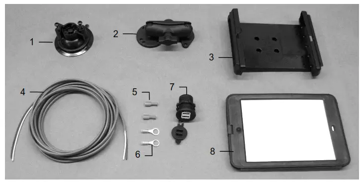
| Ref | Description | Part # | Qty |
| 1 | Suction cup mount | 001-2012SCM | 1 |
| 2 | Ram mount | 001-2012H | 1 |
| 3 | iPad Mini spring load cradle (Mini 1,2,3) | 001-2012SLC | 1 |
| 4 | 16 gauge power wire | Hardware | 1 |
| 5 | Female spade connector | Hardware | 2 |
| 6 | Eye loop connector | Hardware | 2-Jan |
| 7 | iPad Mini Charger 12V | 001-2012P | 1 |
| 8 | iPad Mini 2 case | 001-2012C2 | 1 |
| NP | 4 amp fuse | Hardware | 1 |
| Mounting Kit Assembly | 030-2012MK (Includes All Parts) | ||
Installation Instructions
- Identify a 12V power source for wires to connect.
a. Eye loops included if wiring directly to the battery is desired. - b. Test for key power source if preferred to have power to the USB shut off with the key.
- Once the power source is identified, cut wires to the desired length.
- Crimp the two supplied quick connectors onto each white and black wire.
- Remove the round-locking plastic nut from the USB plug before connecting the wires. Black (+) White (-).
- The wires will then be hooked to the designated terminals on the bottom of the USB plug 6. Drill a 1 1/8” hole in the preferred mounting location. Be sure to clean any sharp edges after drilling.
- Feed the wires through the mounting hole.
- If using the round plastic nut to secure the plug in place, slide the nut back over the wiring before connecting the wires to the powered source
- Connect the wires to the identified power source if easier to do so before tightening the plug into place.
- Tighten the plug using either the round plastic nut or mounting plate and two screws, both options supplied.
- Once connected, hook a USB charging cord into the plug and connect a mobile device/tablet to ensure the plug is operating as you wish (key power working properly if necessary).
NOTE: This plug is not designed to charge two iPads. System damage could occur if this is attempted. The system will charge a mobile phone and iPad simultaneously without a problem.
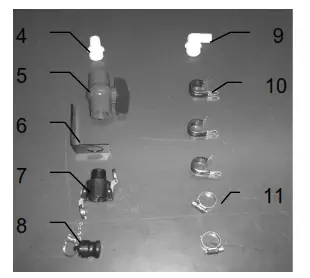
437-SO Installation Kit
| Ref | Description | Part# | Qty | Description | Part# | Qty |
| 1 | Shield holder | 001-4704E2 | 1 | Tip – Low – Silver | 004-650033-SS | 3 |
| 2 | Spray shield | 001-4703GK | 1 | Tip – Low – Green | 004-XR110015VS | 1 |
| 3 | Straight fitting | 003-A1414 | 5 | Tip – Low – Red | 004-XR11004VS | 1 |
| 4 | Tee | 003-TT14 | 3 | Tip – High – White | 004-650050-PT | 2 |
| 5 | Plug | 003-F14 | 1 | Tip – High – Orange | 004-XR11001VS | 1 |
| 6 | Hose | 002-9016 | 3 | Tip – High – Blue | 004-XR11003VS | 1 |
| 7 | Elbow | 003-EL1414F | 2 | Tip – High – Grey | 004-XR11006VS | 1 |
| 8 | Nozzle body | 003-4722 | 5 | |||
| 9 | Nozzle cap | 003-4723 | 5-Jan | |||
| 10 | Tip strainer | 004-4213-200 | 5 | |||
| 11 | Lynchpin | 008-4576 | 2 |
Notes
……………………………………
…………………………………….
…………………………………..
………………………………….
WARRANTY AND LIABILITY AGREEMENT
Harvest Tec, Inc. will repair or replace components that are found to be defective within 12 months from the date of manufacture. Under no circumstances does this warranty cover any components which in the opinion of Harvest Tec, Inc. have been subjected to negligent use, misuse, alteration, or accident, or if repairs have been made with parts other than those manufactured and obtainable from Harvest Tec, Inc.
Our obligation under this warranty is limited to repairing or replacing free of charge to the original purchaser any part that in our judgment shows evidence of defective or improper workmanship, provided the part is returned to Harvest Tec, Inc. within 30 days of the failure. Parts must be returned through the selling dealer and distributor, and transportation charges prepaid.
This warranty shall not be interpreted to render Harvest Tec, Inc. liable for injury or damages of any kind, direct, consequential, or contingent, to persons or property. Furthermore, this warranty does not extend to loss of crop, losses caused by delays or any expense prospective profits or for any other reason. Harvest Tec, Inc. shall not be liable for any recovery greater in amount than the cost or repair of defects in workmanship.
There are no warranties, either expressed or implied, of merchantability or fitness for a particular purpose intended or fitness for any other reason.
This warranty cannot guarantee that existing conditions beyond the control of Harvest Tec, Inc. will not affect our ability to obtain materials or manufacture necessary replacement parts.
Harvest Tec, Inc. reserves the right to make design changes, improve design, or change specifications, at any time without any contingent obligation to purchasers of machines and parts previously sold.
Note: The warranty registration card supplied with the installation manual must be filled out and returned to the manufacturer within fifteen days of purchase. Without a record of receipt of warranty registration at the manufacturer, the warranty is not valid.
Revised 02/01/2012
HARVEST TEC, INC.
P.O. BOX 63
2821 HARVEY STREET
HUDSON, WI 54016 USA
PHONE: 715-386-9100
FAX: 715-381-1792
Email: [email protected]


