Munters CX24P1 CX Circulation Fan 24 Inch Instruction Manual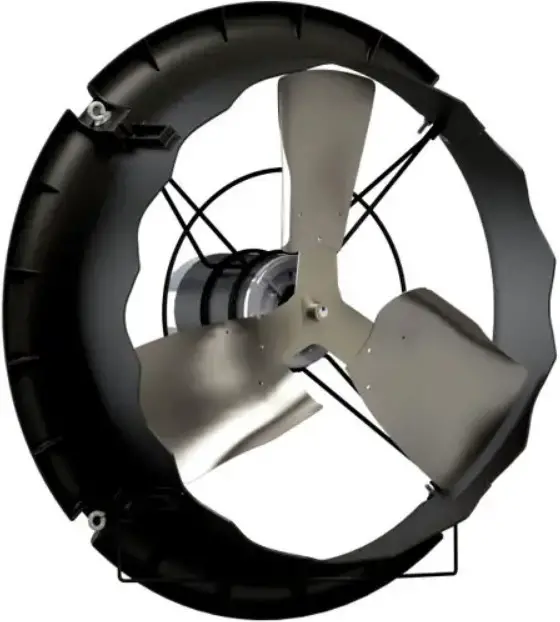
Unpacking the Equipment
Before beginning installation, check the overall condition of the equipment. Remove packing materials, and examine all components for signs of shipping damage. Any shipping damage is the customer’s responsibility and should be reported immediately to your freight carrier. Fan is shipped complete with all accessories.
Parts List
Each CX24P1/CX24P3/CX24PW1/CX24PW3 Fan includes:
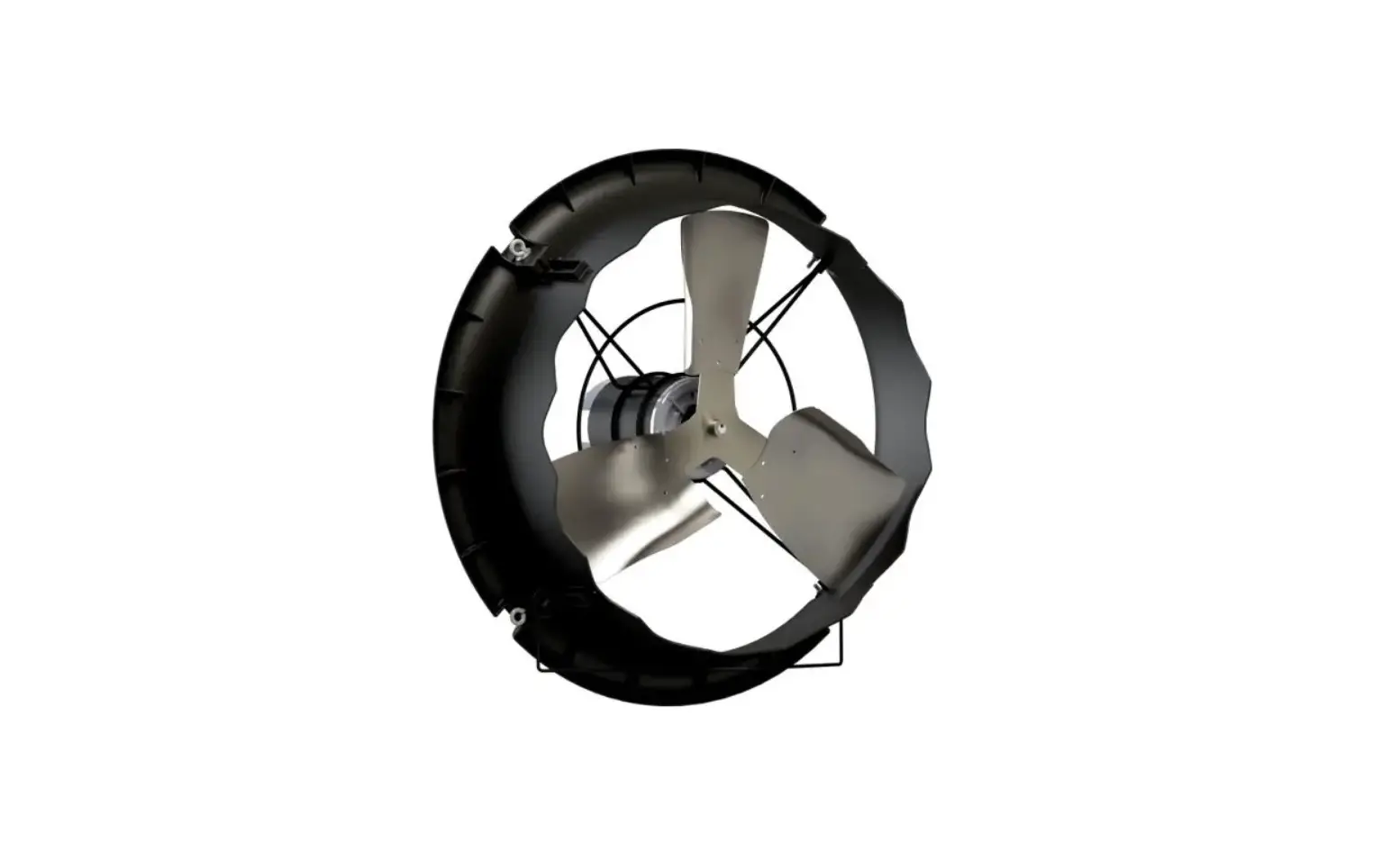
1 – Direct Drive Circulation Fan
Each CX24P1G/CX24P3G/CX24PW1G/CX24PW3G Fan with Guard includes:
1 – Direct Drive Circulation Fan
1 – Guard, Inlet/Outlet Pair, PWDCTD
1 – Hardware Package as follows:
HP1246 – Fan with Guard
ID Qty. Cat. No. Description
[A] 4 KS0650 1 ⁄4”-20 x ⁷⁄₈” Truss Head Bolt, SS
[B] 8 KN1705 1 ⁄4”-20 Hex, Nylock Nut, ZP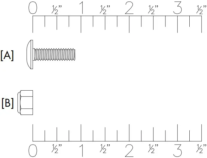
Fan Dimensions
Fan Specifi cations:
Hertz: 60 50 – 60
Voltage: 115/230VAC or 190 – 208-230/380 – 460VAC
Phase: 1 or 3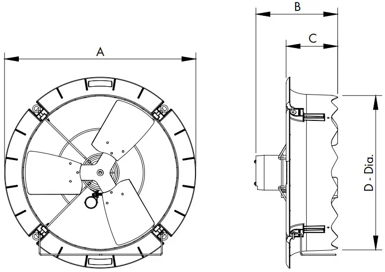
CAT. NO. FAN DIA.
NO. OF BLADES A B C D – Dia. (O.D.)
CX24 24” 3 303 ⁄4” 127 ⁄8” 81 ⁄4” 243 ⁄4”
Installation Instructions
Fan Installation
Step 1
For Horizontal Airflow attach chain to 2 of the Eye Bolts on the fan and then hang the fan from truss. See Figure 1A. Chain and hanging hardware not provided. If it is desired to pull the fan up out of the way when not in use for cleaning, then attach a cable or rope to the Lift Bracket and use a winch or actuator to pull the fan up. See Figure 1B.
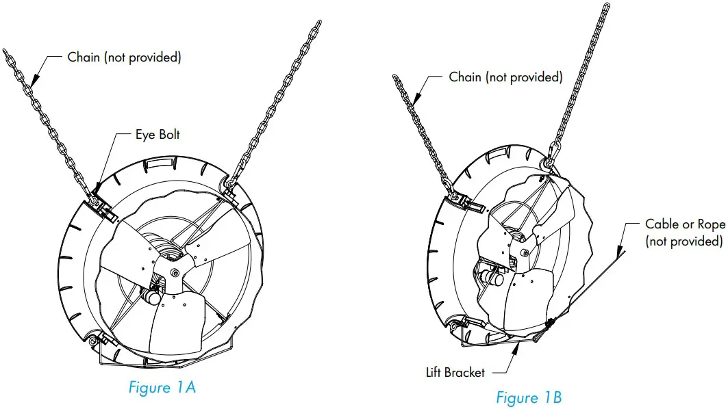
Step 2
For Vertical Airflow attach chain to 4 of the Eye Bolts on the fan and then hang the fan from trusses. See Figure 2. Chain and hanging hardware not provided.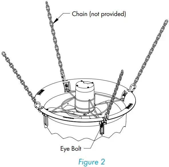
IMPORTANT
If installing fans near heaters, it is recommended to install the CX24 Fan at a location far enough from heaters that will give a maximum temperature of 150°F. This should be approximately 2-3 ft. from the heater.
Optional Guard Installation
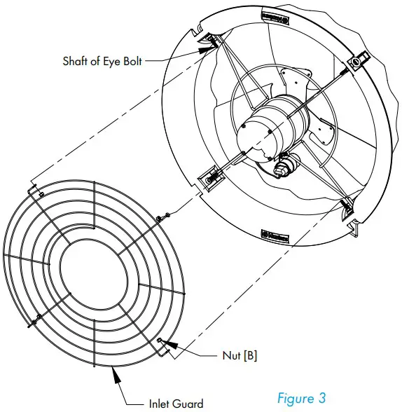
Step 3
The Inlet Guard is the one with the large inner hole to go over the motor. With the eyelets on the guard pointing into the fan slip the eyelets over the shaft of the Eye Bolts and fasten using (4) Nuts [B]. See Figure 3.
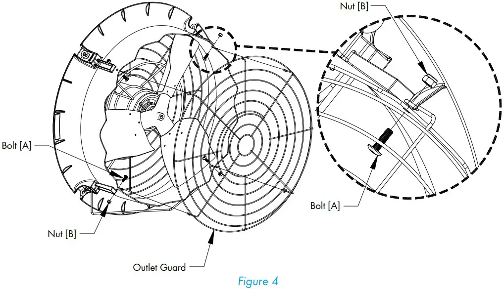
Step 4
The Outlet Guard is the one with the small inner hole. With the eyelets on the guard pointing toward the fan, align the eyelets with the holes in orifice on the outside of the fasten using (4) Bolts [A] and Nuts [B]. The head of the bolt goes on the inside of the orifice and the nut goes on the outside. See Figure 4.
Electrical Wiring
All wiring should be installed in accordance with National, State, and Local electrical codes. Fans used to ventilate livestock buildings or other rooms where continuous air movement is essential should be connected to individual electrical circuits, with a minimum of two circuits per room. For electrical connection requirements, refer to diagram on motor nameplate and to information enclosed with the Munters environmental control to be used. After wiring check for proper motor rotation.
Single Phase Fans: motor overload protection should be provided for each fan. A Circuit Breaker Switch or slow blow motor type fuses must be used, See Figure 5A. See form QM1400 for proper size. Three Phase Fans: motor overload protection should be provided for each fan. A three-pole motor starter or slow blow motor fuses must be used. See Figure 5B.
If a frequency drive (inverter) is used, confirm that motors are rated for inverter duty at the voltage used. Shielded power cable between frequency drive and each motor is highly recommended. Installation of line reactors is recommended to reduce voltage spikes and harmonic distortion. Supplemental motor overload protection is also recommended.
NOTE: A safety cut-off switch should be located adjacent to each fan.
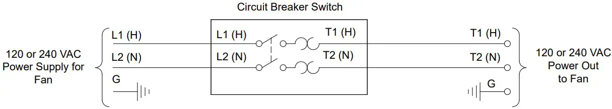
Single Phase – Motor Overload Protection with Disconnect (SY2000 or Equivalent)
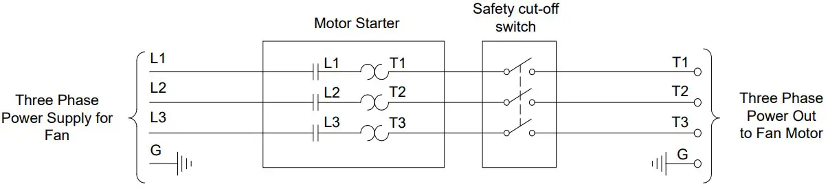
Three Phase – Motor Overload Protection with Disconnect
KEY:
L1=Line 1
L2=Line 2
L3=Line 3
H=Hot
N=Neutral
G=Ground
NOTE: Information in parenthesis refers to 120 VAC control.
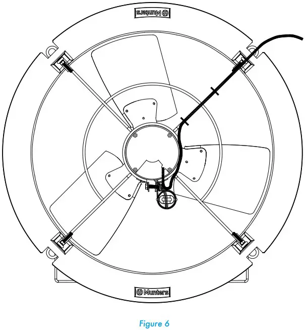
Recommended Wire Routing:
As the power cable exits the back of motor form a drip loop and then run power cable up along leg of motor mount and “Zip” tie the cable to leg to prevent cable from getting tangled. See Figure 6. Then run the cable out the back of fan to the circuit breaker or control panel.
Three Phase Fans:
- The use of a quality frequency drive and the installation of line reactors is recommended to reduce voltage spikes and harmonic distortion.
- Minimum operating frequency of 30 Hz.
- Will require three pole contractors with overload protection (by others).
Operation
INITIAL START-UP: With electrical power off, verify that the fan propeller turns freely and that all fasteners are secure. Turn on electrical power and confirm that the fan operates smoothly.
ADJUSTMENTS: Set the fan control to the temperature shown on your ventilations system drawing, or to a value which will provide the desired environmental conditions.
Single Phase Fans: When variable speed controls are used, the fan’s idle speed will need to be set to the recommended minimum airflow rate. Refer to the procedures included with each control. The table below provides airflow rates at various propeller speeds for fans wired for 240 VAC.
Maintenance
The following inspection and cleaning procedures should be performed monthly:
- INSPECT PROPELLER: Check that propeller is secure on motor shaft and that there are no signs of damage. The blades are of a self-cleaning design and should not require maintenance.

- CLEAN regularly for best results:
- FAN MOTOR: Remove any dust accumulation from motor using a brush or cloth. (DO NOT use a pressure washer). A clean motor will run cooler and last longer. At the same time, verify that the motor is secure in its mount.
- GUARD: Clean any dust or feathers from fan guards using a brush. Dirty guards can reduce airflow.
- CHECK FASTENERS: For safety, all fasteners should be inspected 1 month after initial operation and yearly thereafter. Tighten any loose connections.
- INSPECT FAN CONTROL: With power disconnected, inspect all electrical connections. Wiring should be secure and in good condition. Remove any dust build-up from control case and sensor using a soft brush or cloth. NEVER CLEAN ELECTRICAL EQUIPMENT WITH A PRESSURE WASHER!
Troubleshooting
| SYMPTOM | POSSIBLE CAUSES | CORRECTIVE ACTION | ||
| Fan Not Operating | 1. | Fan control set above room | 1. | Set to a lower temperature |
| temperature | 2. | Replace fuse or reset breaker | ||
| 2. | Blown fuse or open circuit breaker | 3. | Realign motor in fan housing | |
| 3. | Propeller blade contacting fan housing | 4. | Repair or replace control | |
| 4. | Fan control defective | 5. | Repair or replace motor | |
| 5. | Motor defective | |||
| Fan Operating- | 1. | Variable speed control improperly | 1. | See Operation, Step 2 for adjustment guidelines |
| Insufficient | adjusted | 2. | Clean guard | |
| Airflow | 2. | Guard dirty | ||
| Excessive Noise | 1. | Propeller blade contacting fan housing | 1. | Sand fan housing to remove high spot |
| 2. | Motor bearing defective | 2. | Repair or replace motor bearings | |
| 3. | Frequency drive improperly adjusted | 3. | See operation, Step 2 for adjustments guidelines | |
| Excessive | 1. | Motor loose on mount | 1. | Tighten fasteners |
| Vibration | 2. | Propeller damaged | 2. | Replace propeller |
| 3. | Motor shaft bent | 3. | Repair or replace motor | |
| Fan never turns off | 1. | Override thermostat set incorrectly | 1. | Set to the correct temperature |
| 2. | Control set for continuous operation | 2. | Set speed control correctly |
Exploded View
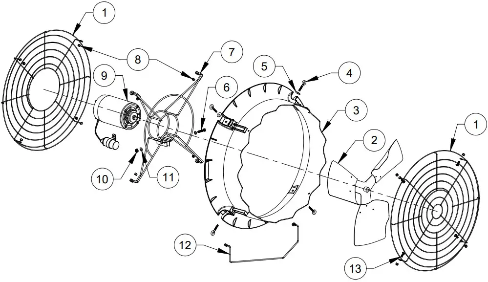
| 1 | FH1624 | Guard Inlet/Outlet Pair, PWDR CTD (Guard Kit) | 1 |
| 2 | FP1724 | Propeller, 24”DD, 3-Blade, CX24, GZ | 1 |
| 3 | FH4224B | Orifice Panel, 24″ CX Fan, PP, BLK | 1 |
| FH4224W | Orifice Panel, 24″ CX Fan, PP, WHT | 1 | |
| 4 | KS2757 | ¼”-20 x 2.5″ Closed Eye Bolt, SS | 4 |
| 5 | KW3012 | ¼” x 1″ O.D. Flat Washer, SS | 2 |
| 6 | KS1029 | 7⁄₁₆”-18 x 1.75″ Hex Head Bolt, SS | 1 |
| 7 | FH2524 | Motor Mount, 24″ CX Fan, PWDR CTD | 1 |
| 8 | KN1705 | ¼”-20 Nylock Nut, SS (Fan/Guard Kit) | 4/8 |
| 9 | FM1108C | 24” DD, Motor w/ capacitor, ¹⁄₃ HP, 1075 RPM, 48 Fr., 1 ph., 115/230V | 1 |
| FM1074 | 24” DD, Motor, ¹⁄₃ HP, 1140 RPM, 48 Fr., 3 ph., 230/460V | ||
| 10 | KN0704 | 7⁄₁₆”-18 Hex, Serrated Flange Nut, SS | 1 |
| 11 | KW3004 | 7⁄₁₆” Narrow Type-A Flat Washer, SS | 2 |
| 12 | FH1324 | Lift Bracket, 2 Point Conn,CX24 Fan, PWDR CTD | 1 |
| 13 | KS0650 | 1⁄4”-20 x ⁷⁄₈” Truss Head Bolt, SS (Guard Kit) | 4 |


