
Hytera EDS50 Wall Mounted Docking Station User Manual
Preface
Welcome to the world of Hytera and thank you for purchasing this product. To derive optimum performance from the product, please read this manual carefully before use.
This manual is applicable to the following product:
EDS50 Wall-mounted Docking Station
Icon Conventions
The following icons are available through this manual:
![]() CAUTION: indicates situations that could cause damage to your product or bodily injury.
CAUTION: indicates situations that could cause damage to your product or bodily injury.![]() NOTE: indicates tips that can help you make better use of your product.
NOTE: indicates tips that can help you make better use of your product.
Copyright Information
Hytera is the trademark or registered trademark of Hytera Communications Corporation Limited (the Company) in the People’s Republic of China (PRC) and/or other countries or areas. The Company retains the ownership of its trademarks and product names. All other trademarks and/or product names that may be used in this manual are properties of their respective owners.
The product described in this manual may include the Company’s computer programs stored in memory or other media. Laws in PRC and/or other countries or areas protect the exclusive rights of the Company with respect to its computer programs. The purchase of this product shall not be deemed to grant, either directly or by implication, any rights to the purchaser regarding the Company’s computer programs. The Company’s computer programs may not be copied, modified, distributed, decompiled, or reverse-engineered in any manner without the prior written consent of the Company.
Disclaimer
The Company endeavors to achieve the accuracy and completeness of this manual, but no warranty of accuracy or reliability is given. All the specifications and designs are subject to change without notice due to continuous technological development. No part of this manual may be copied, modified, translated, or distributed in any manner without the prior written consent of the Company.
We do not guarantee, for any particular purpose, the accuracy, validity, timeliness, legitimacy or completeness of the third-party products and contents involved in this manual.
If you have any suggestions or would like to receive more information, please visit our website at https://www.hytera.com.
Packing List
Unpack carefully and check that you have received the following items. If any item is missing or damaged, contact your dealer.
| Item | Qty. (PCS) | Item | Qty. (PCS) |
| Docking Station | 1 | WLAN Antenna | 2 |
| Power Cord | 1 | Bracket | 1 |
| Network Cable | 1 | Disk | 1 |
| M8 x 60 mm Expansion Bolt | 7 | Documentation Kit | 1 |
![]() NOTE
NOTE
Figures in this manual are only for reference.
Product Over view
Product Layout
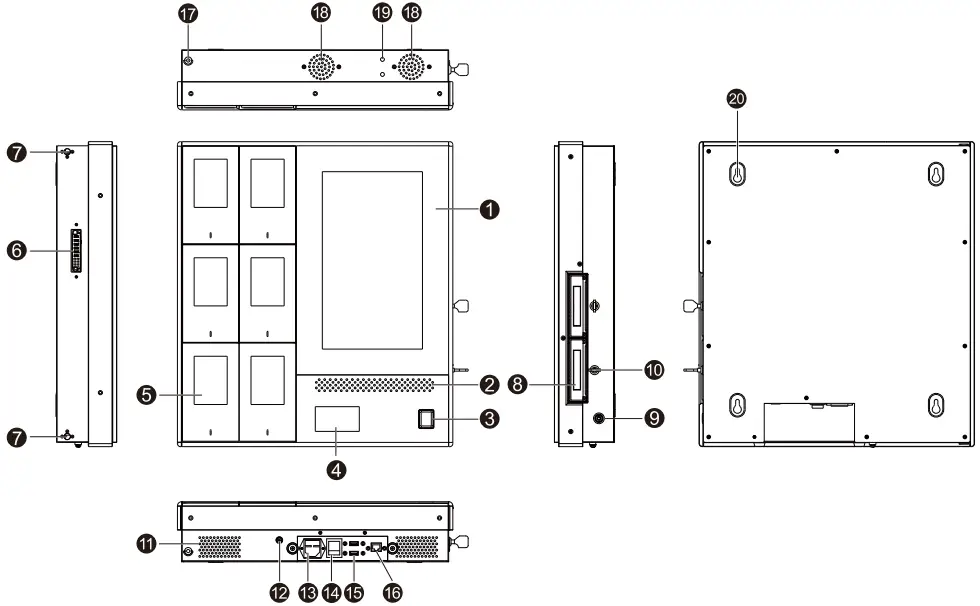
| No. | Part Name | No. | Part Name | No. | Part Name |
| 1 | Display | 8 | Hard Disk Drive (HDD) Bay | 15 | USB Port |
| 2 | Speaker | 9 | Power Button | 16 | Network Port |
| 3 | Fingerprint Reader | 10 | HDD Bay Lock | 17 | Mortise Lock |
| 4 | NFC Card Reader | 11 | Air Inlet | 18 | Fan |
| 5 | BWC Pocket | 12 | Grounding Stud | 19 | WLAN Antenna Port |
| 6 | Connector | 13 | Power Inlet | 20 | Hang Hole |
| 7 | Mortise | 14 | Power Switch | / | / |
Specifications
| Item | Description |
| Dimensions (H x W x D) | Main EDS50: 507 mm x 459 mm x 117 mm Extended EDS50: 507 mm x 205 mm x 117 mm |
| Weight | Main EDS50: 15.6 kg |
| Item | Description |
| l Extended EDS50: 7.8 kg | |
| LCD Display | 13.3-inch LCD touchscreen Resolution: 1920 x 1080 |
| Quantity of Inserted BWCs | 6 |
| CPU | Dual-core, Intel 3855U, 1.6 GHz |
| Memory | 8 GB |
| Hard Disk Capacity | 4 TB |
| USB Port | 2 x USB 2.0 |
| Network Port | RJ45 port |
| WLAN | 2.4 GHz/5 GHz, 802.11a/b/g/n/ac |
| Speaker Power | 3 W |
| Power Supply | Rated voltage: 230 V AC Voltage range: 100 V to 240 V AC |
| Power Consumption | Main EDS50: 100 W Extended EDS50: 60 W |
| Operating Temperature | –10°C to +55°C |
| Storage Temperature | –20°C to +60°C |
| Operating Noise | < 60 dB (A) |
Before Use
Installation Precautions
When you install the EDS50 on the wall, make sure that the following requirements are met.
- Wall materials: solid concrete blocks
- Wall thickness: ≥ 203 mm
- Dimensions of a concrete block (H x W x D): 203 mm x 406 mm x 203 mm
Installation
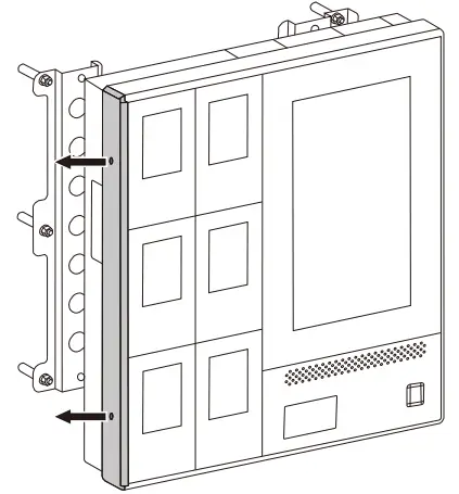
Install the Main EDS50
- Fix the bracket on the wall through expansion bolts.
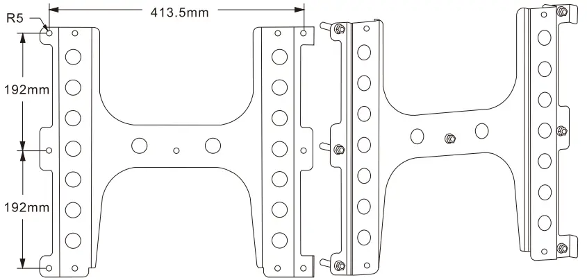
- Align the hang holes on the back of the main EDS50 with the protrusions on the bracket.
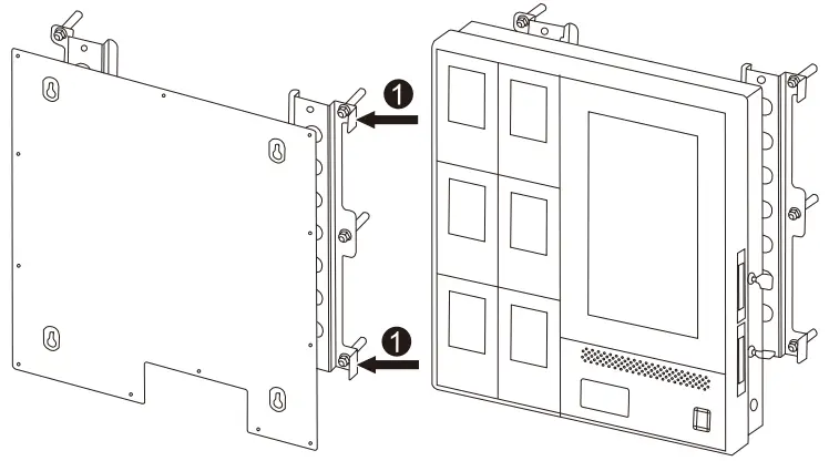
- Gently slide the host straight down until it locks in place.
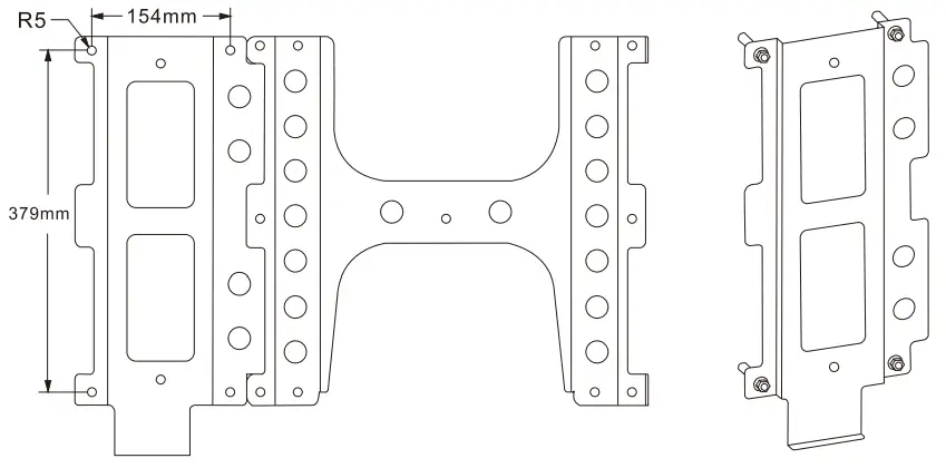
Install the Extended EDS50
![]() NOTE
NOTE
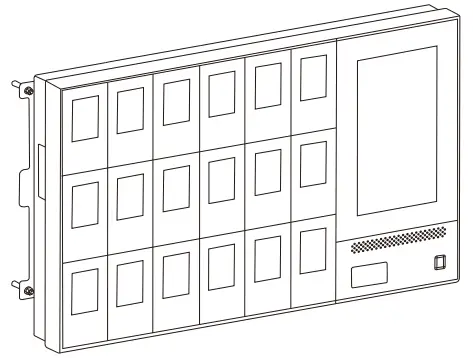
- You can install up to three extended EDS50 including EDS50-Ext1, EDS50-Ext2, and EDS50-Ext3 to the left side of the main EDS50 in order.
- You need to purchase the extended EDS50 separately.
- Align the bracket of the extended EDS50 with that of the main EDS50.
- Fix the bracket on the wall through expansion bolts.
- On the left side of the main EDS50, unscrew the two screws on the aluminum panel, and then remove this panel.
- Align the hang holes on the back of the extended EDS50 with the protrusions on the bracket.
- Gently slide the extended EDS50 to right until the two metal tenons on the extended EDS50 are perfectly inserted into the two mortises on the main EDS50.
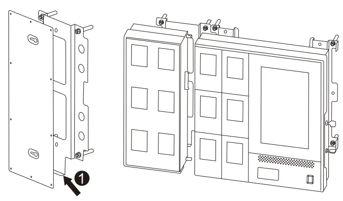
- Tighten the mortise locks.
- Repeat the above steps to install other extended EDS50.
Connect the Ground Wire
- Make a ground wire (≥ 6 mm2) with proper length, and then install OT terminals at both ends of the wire. The metal wires must be completely sealed.
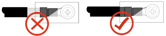
- Connect the OT terminal at one end of the wire to the M6 grounding stud of the EDS50, and the OT terminal at the other end to the internal grounding bar.
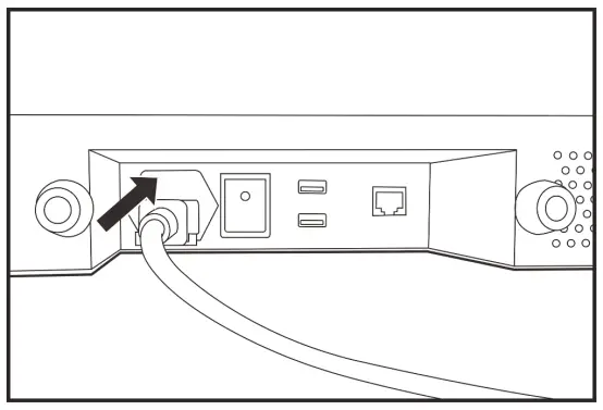
Connect the Power Cord
Connect one end of the power cord to the power inlet of the EDS50, and the other end to the power supply.
Access the Network
To access the network, do either of the following:
- Insert the network cable into the network port of the EDS50.
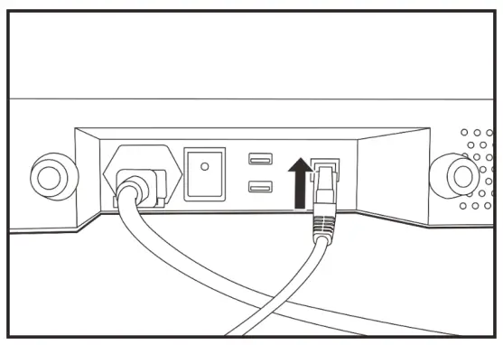
- Install a WLAN antenna.
Basic Operations
Turn On the Product
- Connect the product to the power supply.
- Toggle the Power Switch to on (I) position.
- Press the Power Button
Turn Off the Product
- Press the Power Button.
- Toggle the Power Switch to off (O) position
Log In to the Account
You can perform the related operations only after login.
Through Password
- In the upper right corner, tap
 .
. - In the Login dialog box, enter the user name and password.
The initial username is “admin”, and the initial password is “99999999” NOTE
NOTE
The “admin” user has all permissions of the product, and can create and manage common users. For details, see 4.7.1 Add the User. - Tap Login.
(Optional) Through Fingerprint
Both the “admin” user and common users can log in to the account through fingerprints. To add the fingerprint, see 4.7.2 (Optional) Add the Fingerprint.
- In the upper right corner, tap .
- Press your finger on the fingerprint reader.
Log Out of the Account
- In the upper right corner, tap .
- Tap OK.
![]() NOTE
NOTE
If the product remains idle for more than ten minutes, it will automatically log out.
Set Data Acquisition Parameters
You can set the parameters that are used to acquire digital evidence from BWCs by the product and the Digital Evidence Management (DEM). This operation is available only to the “admin” user.
- In the upper right corner, tap
 .
. - Tap
 , and then select the Acquisition Settings tab.
 - Set the following parameters.
Module Parameter Description Basic Settings File Storage Path Set the storage path of digital evidence acquired from BWCs. Device Password Set the password for data acquisition. IDS Number Unique identifier of the product for the DEM. Auto Register When Auto Register is checked, no authorization is required for the BWC to connect to the product. Auto-upload Settings DEM Address Set the address and port number of the DEM to which the product automatically uploads evidence files. Safe Mode Safe Mode needs to be checked only when the DEM server is in safe mode. File Upload Set whether to upload local digital evidence to the DEM. Delete after upload Set whether digital evidence is automatically deleted after being uploaded to the DEM. Scheduled Set the time interval for uploading digital evidence to the DEM from the product. If Scheduled is cleared, the product will upload digital evidence to the DEM immediately after the evidence is collected.
System Mark Set the type of digital evidence to be uploaded automatically.
All: All digital evidence will be uploaded.Module Parameter Description Important: Only the marked digital evidence will be uploaded.
Not important: Only the unmarked digital evidence will be uploaded.Days of Electronic Evidence Preservation Not Important Set the retention time for unmarked digital evidence. Important Set the retention time for marked digital evidence. - Tap OK.
Set Ports
You can set the mapping relationship between the port panel on the product and the physical port to which the BWC is connected, so that you can quickly find the BWC. This operation is available only to the “admin” user.
- In the upper right corner, tap .
- Tap , and then select the Port Settings tab.
- Set the total number of ports in Maximum Ports, and then tap Change.
- Connect the BWC to physical ports of the product from right to left.
- Connect the BWC to the next port until the port panel highlights dark blue.
- If the highlighted port panel is inconsistent with the physical port, drag the panel to the one consistent with the= physical port.
For example, when the BWC is connected to the product through the COM6 port, the highlighted port panel is supposed to Port 6 but now it is Port 1. In this case, drag Port 1 to the position of Port 6 as shown in the following figure. After that, when the BWC is connected to the product through the COM6 port, the highlighted port panel will be Port 6.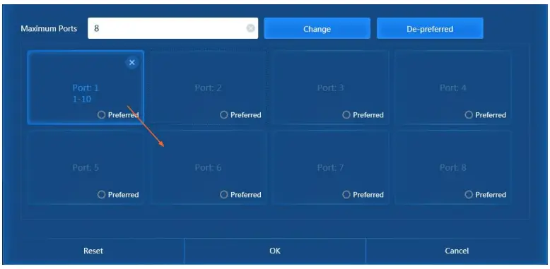
- (Optional) Select a port, and then select Preferred.
The product will first acquire data from the BWC connected to this port and suspend data acquisition from other ports automatically. After the data acquisition from this port completes, other ports resume.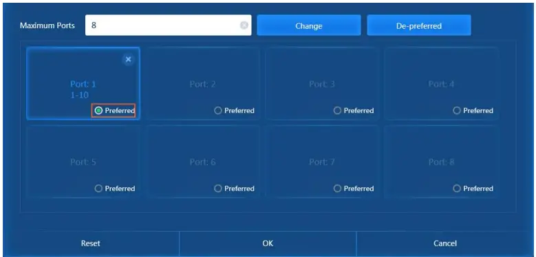
- Tap OK.
Manage Users
Only the “admin” user can manage common users, including adding the user, adding the fingerprint, resetting the password, and clearing the fingerprint.
Add the User
- In the upper right corner, tap .
- Tap
 , and then select the User tab.
 - Tap New.
- In the New dialog box, enter the username.
The default password of the new user is “111111” - Tap OK.
(Optional) Add the Fingerprint
The “admin” user can add the fingerprint for himself and common users. Then the “admin” user and common users can log in to the product by the fingerprint.
- In the upper right corner, tap .
- Tap , and then select the User tab.
- Tap Fingerprint 1 or Fingerprint 2.
- In the New Fingerprint dialog box, add the fingerprint according to the prompt
Reset the Password
The “admin” user can reset the password of common users to “111111”.
- In the upper right corner, tap .
- Tap , and then select the User tab.
- Tap Reset Password.
- Tap OK.
Clear the Fingerprint
![]() CAUTION
CAUTION
This operation will clear all fingerprint records on the product.
- In the upper right corner, tap .
- Tap , and then select the User tab.
- Tap Clear Fingerprint.
- Tap OK.
Manage Devices
You can add, import, approve, and edit the BWC.
Add the Device
- In the upper right corner, tap .
- Tap , and then select the Devices tab.
- Tap Add.
- Set the following parameters.
Parameter Description SN Serial number and unique identifier of a BWC. Officer ID ID of the officer using the BWC. Officer Name Name of the officer using the BWC. - Tap OK.
Import the Device
You can import BWCs in batches.
- In the upper right corner, tap .
- Tap , and then select Devices tab.
- Tap Download template.
- Open the template, and then fill in the following parameters.
Parameter Description SN Serial number and unique identifier of a BWC. Officer ID ID of the officer using the BWC. Officer Name Name of the officer using the BWC. - Tap Import, and then tap Open.
Approve the Device
If the Auto Register feature is disabled, the product needs to approve the initial access of the BWC.
- In the upper right corner, tap .
- Tap , and then select the Devices tab.
- Tap
 .
.
Edit the Device
- In the upper right corner, tap .
- Tap , and then select the Devices tab.
- Tap
 .
. - In the Edit dialog box, edit the BWC and officer information.
- Tap Parameters.
Manage Officers
Add the Officer
- In the upper right corner, tap .
- Tap , and then select Officer Management tab.
- Tap Add.
- In the New Officer dialog box, fill in the following parameters.
Parameter Description Officer ID ID of the officer using the BWC. Officer Name Name of the officer using the BWC. Card ID ID of the NFC card used by the officer. - Tap OK.
Add the Fingerprint
The “admin” user can add the fingerprint for officers to verify identity when they borrow and return BWCs.
- In the upper right corner, tap .
- Tap , and then select the Officer Management tab.
- In the officer list, tap Fingerprint 1 or Fingerprint 2.
- In the New Fingerprint dialog box, add the fingerprint according to the prompt.
Apply for/Import the License
You have 90 days free trial to use all functions of the product. After that, you must apply for the license to use these functions again.
Apply for the License
Ensure that you have plugged the dongle to the product.
- In the upper right corner, tap .
- Tap
 .
. - In the About dialog box, tap Export License.
- Choose the file save path, and then enter the file name.
- Tap Save.
- Send the key license application file to Hytera to obtain the license
Import the License
Ensure that you have obtained the license file (in .license format) and plugged the dongle to the product.
- In the upper right corner, tap .
- Tap .
- In the About dialog box, tap Import License.
- Choose the obtained license, and then tap Open.
- Tap OK.
Acquire Data
- Turn on the BWC.
- Do one of the following to open the BWC pocket door.
- Method 1
a. In the Devices interface of the product, select the BWC.
The Borrow or Return dialog box pops up.
b. Tap the NFC card or the fingerprint to verify identify.
The officer information and fingerprint have been configured. For details, see 4.94.9 Manage Officers.
After the officer information is matched, the BWC pocket door will be automatically opened. - Method 2
a. Log in to the product as the “admin” user.
b. In the upper right corner, tap.
c. Tap, and then select the Officer Management tab.
d. Tap Open all doors.
e. Tap OK.
- Method 1
- Do one of the following to connect the BWC to the product.
- Drop the BWC into the BWC pocket.
- Connect the BWC to the USB cable in the BWC pocket
- Close the BWC pocket door.
More Functions
For more details of the product functions, refer to Hytera IDS Operation Guide.
To obtain the manual, tap ![]() in the upper right corner, and then tap
in the upper right corner, and then tap ![]() .
.
Troubleshooting
| Phenomena | Analysis | Solution |
| Turn on the product, and then press the DEL key to enter the BIOS. | ||
| The product fails to be turned on after the USB flash drive or other USB device is inserted. | The BIOS startup item may be set incorrectly. | In the Boot tab, set the first startup item to system disk. |
| Press the F10 or F4 key to save your changes and restart the product. | ||
| Power on the product, and then press the DEL key to enter the BIOS. | ||
| The boot mode may be incorrect. | Check and ensure that the boot mode is UEFI mode. | |
| The display does not light up after power-on. | Press the F10 or F4 key to save your changes and restart the product. | |
| The HDD may be inserted improperly into the HDD bay of the product. | ||
| Remove the HDD, and then insert it into the HDD bay of the product again. | ||
| The power supply may enter the self-protection state. | Disconnect the product from the power supply, and then restart the product. | |
| The fan is loud. | The heat dissipation may be poor. | Check and ensure that the air inlet/outlet of the product is not blocked. Clean up the dust on the dust flakes. |
| The display is unresponsive or inaccurate when you tap it. | The display may be stained. | Use an alcohol cloth to clean up the display. |
| The product fails to be connected to the power supply. | The power supply may enter the self-protection state. | Disconnect the product from the power supply, and then restart the product. |
| The fuse may blow. | Replace the fuse. | |
| The power cord may be connected improperly. | Replace the power cord. |
| Phenomena | Analysis | Solution |
| The product shows a partially blurred screen. | The display may malfunction. | Replace the display. |
| The product fails to acquire the digital evidence from the BWC. | The BWC may be inserted improperly into the slot of the product. | Remove the BWC, and then insert it into the slot of the product again. |
| The BWC fails to be removed after power-off. | The electronic lock may fail to work. | Connect the product to the Uninterruptible Power Supply (UPS), turn on the product, and then open the BWC pocket door. Remove the rear cover of the product, open the electronic lock, and then open the BWC pocket door. |
If the above solutions cannot solve your problems, or you may have some other queries, contact us or your local dealer for more technical support.
Care and Cleaning
To guarantee optimal performance as well as a long service life of the product, follow these tips.
Product Care
- Do not pierce or scrape the product.
- Keep the product far away from substances that can corrode the circuitry.
- Keep the product dry
Product Cleaning
![]() NOTE
NOTE
Turn off the product and remove the power cord before cleaning.
- Clean up the dust and fine particles on the product surface regularly with a clean and dry lint-free cloth or a brush.
- Use neutral cleanser and a non-woven fabric to clean the product after long-time use. Do not use chemical preparations such as stain removers, alcohol, sprays, or oil preparations, so as to avoid surface and case damage.
- Make sure that the product is completely dry before use.
FCC Statement
This equipment has been tested and found to comply with the limits for a Class B digital device, pursuant to part 15 of FCC Rules. These limits are designed to provide reasonable protection against harmful interference in a residential installation. This equipment generates and can radiate radio frequency energy. If not installed and used in accordance with the instructions, it may cause harmful interference to radio communications. However, there is no guarantee that interference will not occur in a particular installation. Verification of harmful interference by this equipment to radio or television reception can be determined by turning it off and then on. The user is encouraged to try to correct the interference by one or more of the following measures:
- Reorient or relocate the receiving antenna. Increase the separation between the equipment and receiver.
- Connect the equipment into an outlet on a different circuit to that of the receiver’s outlet.
- Consult the dealer or an experienced radio/TV technician for help.
Operation is subject to the following two conditions:
- This device may not cause harmful interference.
- This device must accept any interference received, including interference that may cause undesired operation.
Note: Any changes or modifications to this unit not expressly approved by the party responsible for compliance could void the user’s authority to operate the equipment.
FCC Radiation Exposure Statement:
This equipment complies with FCC radiation exposure limits set forth for an uncontrolled environment .
This transmitter must not be co‐located or operating in conjunction with any other antenna or transmitter.
This equipment should be installed and operated with minimum distance 20cm between the radiator &you body.
ISEDC Statement
This device complies with Innovation, Science and Economic Development Canada licence-exempt RSS
standard (s). Operation is subject to the following two conditions:
- this device may not cause interference, and
- this device must accept any interference,including interference that may cause undesired operation of the device.
ISEDC Radiation Exposure Statement:
This equipment complies with ISEDC RF radiation exposure limits set forth for an uncontrolled environment.
This transmitter must not be co-located or operating in conjunction with any other antenna or transmitter.
This equipment should be installed and operated with minimum distance 20cm between the radiator &you body.
operation of 5150-5350MHz is restricted to indoor use only
![]() is the trademark or registered trademark of Hytera Communications Corporation Limited.
is the trademark or registered trademark of Hytera Communications Corporation Limited.
© 2022 Hytera Communications Corporation Limited. All Rights Reserved.
Address: Hytera Tower, Hi-Tech Industrial Park North, 9108# Beihuan Road, Nanshan District, Shenzhen, People’s Republic of China
Postcode: 518057
https://www.hytera.com


