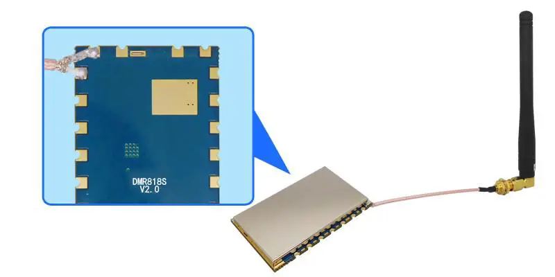
G-NiceRF DMR818S-U Digital Walkie Talkie Module
Descriptions
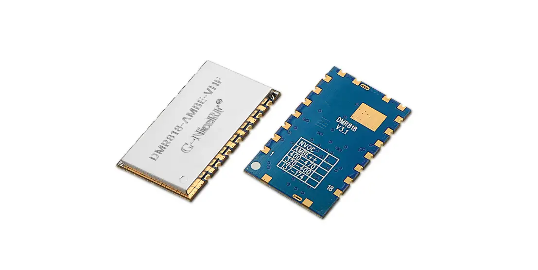
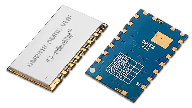
DMR818S-U is a 1W long distance DMR walkie talkie module, it comes with built-in high performance microcontroller, digital mobile radio IC and RF power amplifier. All parameters(CTCSS, CDCSS, SQ, Predefined channels etc.) can be easily modified with protocol. With external power supply, speaker, and audio amplifier, it is easy to become a professional digital walkie talkie. Simplified interface and Ultra small size make this module widely used in various applications and conveniently embedded into various handheld device..
DMR mode:
- Message transmission and reception.
- Enhanced encryption of Voice and Text message.
- Various voice call types: All call, Group call and Private call;
- Reminder for input calling, calling status checking
- Emergency alarm and radio monitor;
- Repeater
Analog mode:
- CTCSS/CDCSS configurable
- Squelch levels configurable
Features
- UHF band frequency: 400~470 MHz
- Distance up to 5Km
- High Sensitivity: -124dBm
- Bit error rate down to 1% under -121dBm
- Independent frequency for Tx and Rx.
- 9 adjustable volume
- Message transmission and reception
- DMR(Digital Mobile Radio)/ Analog walkie talkie
- Built-in EEPROM, data saved even powered off
- 1ppm TCXO crystal
- 51 CTCSS
- 166 CDCSS
Application
- DMR walkie talkie module
- Invisible intercom system
- Building security system
- Audio surveillance system
Electrical Characteristics
| Parameters | Test condition | Min. | Typ. | Max | Unit |
| Voltage range | 3.34 | 4.2 | 5.0 | V | |
| Operating Temperature | -20 | 25 | 80 | ℃ | |
| Frequency range | @UHF | 400 | 470 | MHz | |
| Start time | 2000 | ms | |||
| Uart baud rate | 57600 | bps | |||
| Current Consumption | |||||
| Sleep current | CS pulled low for 3 seconds | < 55 | uA | ||
| Rx current | <135 | mA | |||
| Tx current (high power) | @VCC=4.2V, 1w analog | <1300 | mA | ||
| @VCC=4.2V, 1w digital | <1000 | mA | |||
| Tx current (low power) | @VCC=4.2V, 0.5w analog | <650 | mA | ||
| @VCC=4.2V, 0.5w digital | <500 | mA | |||
| RF Parameters | |||||
| Tolerance of frequency | 1 | 1.5 | ppm | ||
| Modulation sensitivity | 1.5KHz/2.5KHz frequency offset | 6 | 7 | 12 | mv |
| Adjacent-channel power | @12.5K offset | -60 | -62 | dBm | ||||
| Mic input voltage | 0.1 | 1.6 | Vpp | |||||
| CTCSS modulation frequency offset | 0.35 | 0.4 | 0.6 | KHz | ||||
| Modulation characteristics | 300HZ | -13 | -11 | -9 | dB | |||
| 500HZ | -9 | -6 | -5 | dB | ||||
| 1000HZ | -3 | 0 | 1 | dB | ||||
| 2000HZ | 3 | 6 | 7 | dB | ||||
| 3000HZ | 5 | 7 | 11 | dB | ||||
| Rx Parameters | ||||||||
| Sensitivity | Analog (12db SNR) | -120 | dBm | |||||
| Receiving BER(DMR modulation) | @ -118dBm | 5 | % | |||||
| Audio output amplitude | 500 | mV | ||||||
| Audio Output impedance | 30 | KOhm | ||||||
| Adjacent channel selectivity | Offset:+12.5KHz | 60 | dB | |||||
| Offset:+12.5KHz | ||||||||
Functions descriptions
- Voice transmission
“PTT” pin is used to control the voice transmission. Pull low to enable voice transmission; High to end transmission.
Timing operation:
- Voice receiving
After power on, DMR818S-U will enter into receiving mode automatically. It will return back to receiving mode after voice transmission ended.
For details of receiving process, please check “DMR818S-U communication protocol”. - Sleep function
The module can switch work and sleep mode through CS pin. When the CS pin is high, it is the working mode, and when the CS pin is low, it is the sleep mode. In sleep mode, all peripherals of the module are turned off and cannot communicate and respond to serial commands.
Note: CS pin is low level by default, in sleep mode, the user needs to give high level externally to make the module work.
After the CS pin level changes, the state needs 3 seconds to switch. - Switch of Audio amplifier
Pin “SPK_EN” is used to control external audio amplifier. When playing voice, SPK_EN in high level, low level when other status. The timing of SPK_EN as blow:


Brief of Serial Communication Protocol
All the parameters of DMR818S-U can be configured using Serial Communication Protocol.
MSB for the command. Format as below:
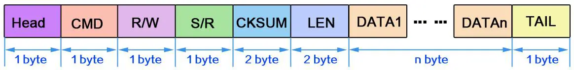
The definition of protocol as below:
| Offset | Flag | Length | Comment | Detail |
| 0 | Head | 1 | Packet header | 0x68 |
| 1 | CMD | 1 | command | 0x01~0x28:parameter function refer to table 1 |
| 2 | R/W | 1 | Read /write | 0x00:reading ; |
| operation | 0x01:writing ; | |||
| (external CPU TX is writing, external CPU RX is | ||||
| reading) | ||||
| 0x02:initiative sending | ||||
| 3 | S/R | 1 | Setting/Responding | setting: 0x01:start answering: |
| 0x00 Done | ||||
| 0x01 busy or fail (note 2) | ||||
| 0x02 No channel or channel errors (note 3) | ||||
| 0x07 module killed | ||||
| 0x09 check error | ||||
| note: message, voice refer to below corresponding specification | ||||
| 4、5 | CKSUM | 2 | Checksum | Checksum for all the packet |
| 6、7 | LEN | 2 | Data length | DATA length, No information, LEN is 0 |
| 8 | DATA | len | Data info | |
| TAIL | 1 | Tail of packet | 0x10 |
| CMD | Function | Message available for All channels or current channel | Message save when Power off (yes / no) |
| 0x01 | Channel change | yes | |
| 0x02 | Receive volume | All | yes |
| 0x03 | scanning | current channel | no |
| 0x04 | Transceiver status checking | current channel | no |
| 0x05 | Signal strength value | current channel | no |
| 0x06 | Various call modes( Call Type) | current channel | no |
| 0x07 | Message mode setting and transmit | current channel | no |
| 0x09 | Emergency alarm | current channel | no |
| 0x0a | Enhancements | current channel | no |
| 0x0b | Mic Gain configuration | All | yes |
| 0x0c | Power-saving mode configuration | All | yes |
| 0x0d | Transceiver frequency | current channel | yes |
| 0x0e | Repeater/off-web | current channel | no |
| 0x10 | Receive/call type, number output | current channel | no |
| 0x11 | Read received data | current channel | no |
| 0x12 | SQ setting | current channel | yes |
| 0x13 | Mode of CTCSS/CDCSS | current channel | yes |
| 0x14 | CTCSS/CDCSS | current channel | yes |
| 0x15 | Monitor switch | current channel | no |
| 0x16 | Bit Error rates | no | |
| 0x17 | High/low power | current channel | yes |
| 0x18 | Contact person | current channel | no |
| 0x19 | Encryption switch | current channel | no |
| 0x1a | Completed initialization | no |
| 0x22 | Transmit contacts information | current channel | no |
| 0x23 | Testing message | current channel | no |
| 0x24 | ID reading | all | no |
| 0x25 | Firmware Version reading | all | no |
| 0x28 | Checking encryption status | current channel | no |
| 0x29 | Set up a contact to receive group calls | current channel | yes |
| 0x30 | Delete group call contact | current channel | yes |
| 0x1B | Set the phone number | current channel | yes |
| 0x31 | Set native color code | current channel | yes |
| 0x32 | Set analog bandwidth | current channel | yes |
| 0x33 | Set time slot | current channel | yes |
| 0xF0 | Restore default parameters | all | yes |
| 0xF2 | Software reset | all | no |
Note 2: When is transmitting, receiving, and configuring, it will show 0x01 to tell setting fail for busy.
Note 3: It show 0x02 for below condition:
- When change to non-exist channel;
- It all happen when configure DMR settings in analogy channel( such as: message, special functions) ,
- Configure analog parameters in DMR channel.
DMR818S-U
DMR818S-U
Pin Assignment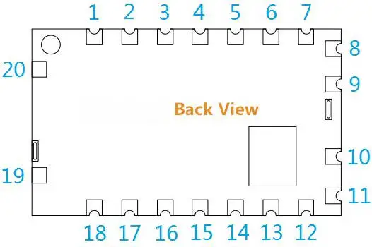
| Pin NO. | Pin name | I/O | Level standard | Description |
| 1 | MIC_IN | I | Microphone or line in | |
| 2 | UART-TX | O | 0-3.3V | Transmit |
| 3 | UART-RX | I | 0-3.3V | receive |
| 4, 12 | NC | |||
| 5 | HST_TXD | O | 0-3.3V | Transmit data pin (for upgrading program) |
| 6 | HST_RXD | I | 0-3.3V | Receive data pin (for upgrading program) |
| 7 | ANT | connect 50 ohm antenna | ||
| 8, 9, 10 | GND | – | Ground | |
| 11 | VCC | – | 0-5V | External and Positive supply 3.3~5V |
| 13 | CS | I | 0-5V | High level for normal working, leave open or pull low to enter sleeping mode |
| 14 | PTT | I | 0-3.3V | Module Input, Transmitting/receiving control, pull low to force the module to enter TX state; pull high for Rx state |
| 15 | +3.3V | – | 3.3V output, connect to 50mA | |
| 16 | LINE_OUT | O | Audio output | |
| 17 | T/R | O | 0-3.3V | Module Output, status of Transmitting/receiving, High for TX and low for Rx |
| 18 | SPKEN | O | 0-3.3V | Audio amplifier control |
| 19, 20 | GND | – | Ground |
Accessories
- Antenna
The antenna is very important for RF communication, Its performance will affect the communication, the module requires the antenna with 50Ω impedance. Universal antennas are Rod antenna, sucker antenna and telescopic antenna, User can choose the right antenna according to their application. We advise to use antennas listed on our website to get better performance.
Mechanism Dimension(Unit: mm)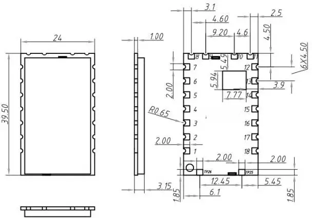
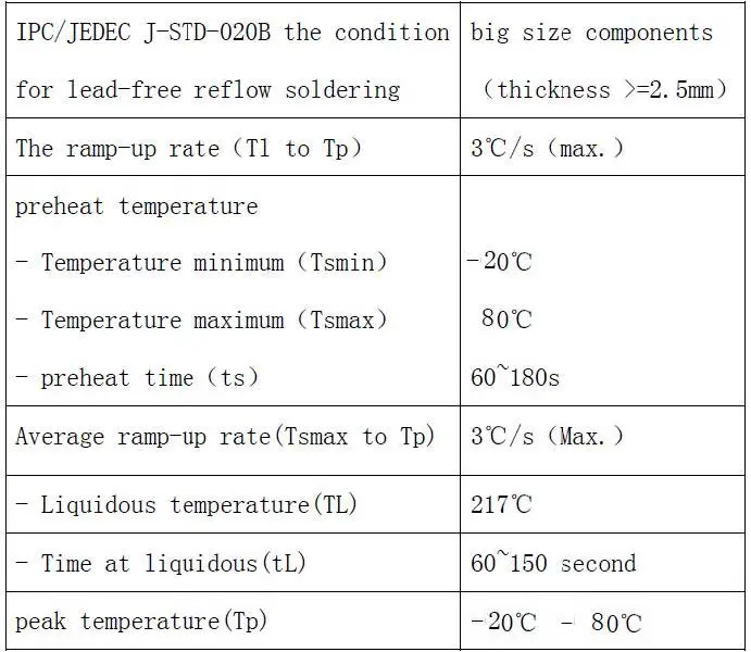
Appendix: SMD Reflow Chart
We recommend you should obey the IPC related standards in setting the reflow profile: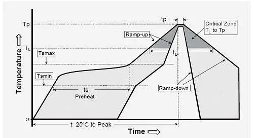
FCC WARNING
Any Changes or modifications not expressly approved by the party responsible for compliance could void the user’s authority to operate the equipment.
This device complies with part 15 of the FCC Rules.
Operation is subject to the following two conditions:
- This device may not cause harmful interference, and
- This device must accept any interference received, including interference that may cause undesired operation.
This equipment has been tested and found to comply with the limits for a Class B digital device, pursuant to part 15 of the FCC Rules. These limits are designed to provide reasonable protection against harmful interference in a residential installation. This equipment generates uses and can radiate radio frequency energy and, if not installed and used in accordance with the instructions, may cause harmful interference to radio communications. However, there is no guarantee that interference will not occur in a particular installation. If this equipment does cause harmful interference to radio or television reception, which can be determined by turning the equipment off and on, the user is encouraged to try to correct the interference by one or more of the following measures:
- Reorient or relocate the receiving antenna.
- Increase the separation between the equipment and receiver.
- Connect the equipment into an outlet on a circuit different from that to which the receiver is connected.
- Consult the dealer or an experienced radio/TV technician for help.
This equipment complies with FCC radiation exposure limits set forth for an controlled environment.
This transmitter must not be co-located or operating in conjunction with any other antenna or transmitter.
This equipment should be installed and operated with minimum distance 20cm between the radiator& your body.
List of applicable FCC rules
CFR 47 FCC PART 90 has been investigated. It is applicable to the modular.
Specific operational use conditions
This module is stand-alone modular. If the end product will involve the Multiple simultaneously transmitting condition or different operational conditions for a stand-alone modular transmitter in a host, host manufacturer have to consult with module manufacturer for the installation method in end system.
Limited module procedures
Not applicable
Trace antenna designs
Not applicable
RF exposure considerations
To maintain compliance with FCC’s RF Exposure guidelines, this equipment should be installed and operated with minimum distance of 20cm from your body and the maximum antenna gain should not exceed 2.5dBi. For modules used in host that not compliance with the requirement, such as less distance or greater antenna gain or in portable device or with other transmitters simultaneously, requires additional evaluation, testing, or testing and Class 2 permissive change.
Antennas
This radio transmitter FCC ID: 2AD66-DMR818S-U has been approved by Federal Communications Commission to operate with the antenna types listed below, with the maximum permissible gain indicated. Antenna types not included in this list that have a gain greater than the maximum gain indicated for any type listed are strictly prohibited for use with this device.
| No. | Antenna Type | Antenna Gain | Impedance | Frequency Range |
| 1 | external antenna | 2.5dBi | 50Ω | 400-470MHz |
Label and compliance information
The final end product must be labeled in a visible area with the following” Contains FCC ID: 2AD66-DMR818S-U”
Information on test modes and additional testing requirements
Host manufacturer is strongly recommended to confirm compliance with FCC requirements for the transmitter when the module is installed in the host.
Additional testing, Part 15 Subpart B disclaimer
Host manufacturer is responsible for compliance of the host system with module installed with all other applicable requirements for the system such as Part 15 B


