![]()
USER MANUAL
PCIe/104 (PCI/104-Express) to PCI Express Adapter
Bottom Stacking Model
CTIM-00056 (0.00) – November 24, 2011
Connect Tech PCIe/104 to PCI Express Adapter – Bottom Stacking Model – User Manual
Copyright Notice
The information contained in this document is subject to change without notice. Connect Tech Inc. shall not be liable for errors contained herein or for incidental consequential damages in connection with the furnishing, performance, or use of this material. This document contains proprietary information that is protected by copyright. All rights are reserved. No part of this document may be photocopied, reproduced, or translated to another language without the prior written consent of Connect Tech, Inc.
Copyright © 2010 by Connect Tech Inc.
Trademark Acknowledgement
Connect Tech Inc. acknowledges all trademarks, registered trademarks and/or copyrights referred to in this document as the property of their respective owners.
Not listing all possible trademarks or copyright acknowledgments does not constitute a lack of acknowledgment to the rightful owners of the trademarks and copyrights mentioned in this document.
Revision History
Revision 0.00 Original Document
Introduction
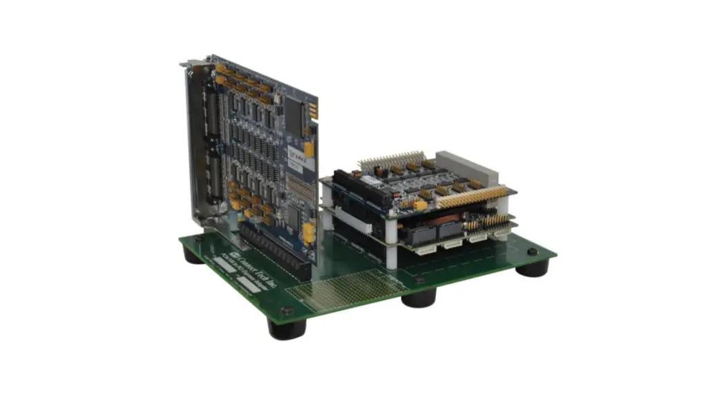
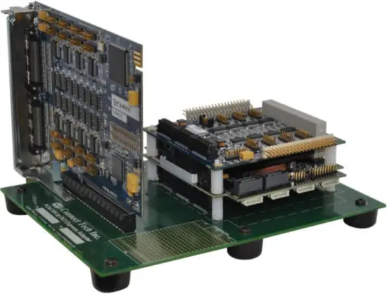
Connect Tech’s PCI/104-Express to PCI Express Adapter enables users to install any x1, x4, x8 or x16 lane PCI Express card in a PCI/104-Express stack.
This convenient adapter board enables the testing, development and deployment for standard PCI Express cards into embedded the PCI/104-Express environment.
Features
- PCI/Express x1, x4, x8, x16 Lane Card Compatible
- PCI/104-Express & PCIe/104 Compatible
- SBC Bottom Stacking Compatible
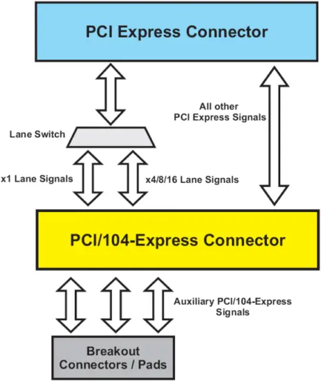
1. Block Diagram
Below is a high level view of the PCI/104-Express to PCI Express Adapter. Aside from the x1 and x16 lane switch the rest of the PCI express signals are direct connections to those of the PCI/104-Express signals. See Table 1 in this manual for a full listing of pinouts and interconnections.
2. Detailed Hardware Description
An ADG021 is depicted below with all of the user accessible locations defined. Further detailed descriptions of these locations will be defined below.
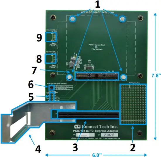
- PC/104 Standoffs
- Prototyping Area
- PCI Express Connector
- PCI Express Support Bracket
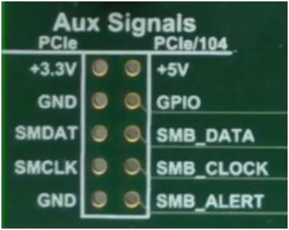
- PCIe/104 Aux Signals
- Power & Lane Select Jumpers
- PCIe/104 Connector
- USB Port 1
- USB Port 0
PCIe Lane and Power Selection Jumper
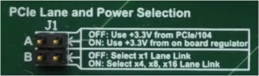
Position A: Should only be installed when you SBC power supply does not supply +3.3V to the PCI/104-Express bus.
Position B: In some cases PCI/104-Express SBC require the PEG_ENA signal to be enabled to use the x16 lane bus, if your SBC requires this please install this jumper.
Auxiliary Signals Jumper Block
Position A: Should only be installed when you SBC power supply does not supply +3.3V to the PCI/104-Express bus.
Position B: In some cases PCI/104-Express SBC require the PEG_ENA signal to be enabled to use the x16 lane bus, if your SBC requires this please install this jumper.
USB Port Connector Pads
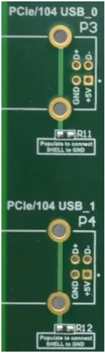
USB Type “B” connectors can be optionally installed by the user. These ports will directly interface with the USB_0 and USB_1 on the PCI/104-Express bus. This is also an option to connect the shell of the USB connector to the PCB ground.
Compatible USB connectors:
| Manufacturer | Part Number |
| Tyco | 292304-X |
| Tyco | 1734176-X |
| Samtec | USB-B-S-X-X-TH-X-XX |
| FCI | 61729-XXXXBLF |
| Contact [email protected] for others. | |
3. Hardware Installation
PC104 Stand-Offs
When installing your PCI/104-Express SBC system onto ADG021, four proper stack height (0.6”) PC/104 standoffs must be used. If standoffs are not used, there is a high likelihood that the PCI/104-Express connector will be damaged. 4 x PC/104 standoffs, 4 x PC/104 nuts and 4 x PC/104 screws are provided to complete your PCI/104-Express SBC installation to the ADG021.
Support Bracket Installation
The ADG021 product ships with a Standard Height PCI Express Custom Support Bracket that can be optionally installed to provide greater stability to the PCI Express add-on card installed into your PCI/104-Express stack.
Installation steps:
- Insert bracket into alignment holes (see photo above for bracket location on PCB)
- Install and tighten each of the 4 supplied nuts.
3. Pinouts and Signal Interconnect
Below is a listing of all signal interconnect between the PCI Express connector and the PCI/104-Express connector. Power, ground and presence detection signals have been removed from this list.
| PCI Express Connector Pinout | PCI/104-Express Connector Pinout | |||
| Connector Side | Pin No. | Pin Name | Pin No. | Pin Name |
| Side A | 5 | SMCLK | no connection | |
| Side A | 6 | SMDAT | no connection | |
| Side A | 9 | JTAG1 | no connection | |
| Side A | 11 | WAKE# | 53 | Reserved / WAKE# |
| Side A | 12 | RSVD | no connection | |
| Side A | 14 | PETp0 | 12 OR 58 | PEx1_0Tp OR PEx16_0T(0)p |
| Side A | 15 | PETn0 | 14 OR 60 | PEx1_0Tn OR PEx16_0T(0)n |
| Side A | 19 | PETp1 | 64 | PEx16_0T(1)p |
| Side A | 20 | PETn1 | 65 | PEx16_0T(1)n |
| Side A | 23 | PETp2 | 70 | PEx16_0T(2)p |
| Side A | 24 | PETn2 | 72 | PEx16_0T(2)n |
| Side A | 27 | PETp3 | 76 | PEx16_0T(3)p |
| Side A | 28 | PETn3 | 78 | PEx16_0T(3)n |
| Side A | 30 | RSVD | no connection | |
| Side A | 33 | PETp4 | 82 | PEx16_0T(4)p |
| Side A | 34 | PETn4 | 84 | PEx16_0T(4)n |
| Side A | 37 | PETp5 | 88 | PEx16_0T(5)p |
| Side A | 38 | PETn5 | 90 | PEx16_0T(5)n |
| Side A | 41 | PETp6 | 94 | PEx16_0T(6)p |
| Side A | 42 | PETn6 | 96 | PEx16_0T(6)n |
| Side A | 45 | PETp7 | 100 | PEx16_0T(7)p |
| Side A | 46 | PETn7 | 102 | PEx16_0T(7)n |
| Side A | 50 | PETp8 | 57 | PEx16_0T(8)p |
| Side A | 51 | PETn8 | 59 | PEx16_0T(8)n |
| Side A | 54 | PETp9 | 63 | PEx16_0T(9)p |
| Side A | 55 | PETn9 | 65 | PEx16_0T(9)n |
| Side A | 58 | PETp10 | 69 | PEx16_0T(10)p |
| Side A | 59 | PETn10 | 71 | PEx16_0T(10)n |
| Side A | 62 | PETp11 | 75 | PEx16_0T(11)p |
| Side A | 63 | PETn11 | 77 | PEx16_0T(11)n |
| Side A | 66 | PETp12 | 81 | PEx16_0T(12)p |
| Side A | 67 | PETn12 | 83 | PEx16_0T(12)n |
| Side A | 70 | PETp13 | 87 | PEx16_0T(13)p |
| Side A | 71 | PETn13 | 89 | PEx16_0T(13)n |
| Side A | 74 | PETp14 | 93 | PEx16_0T(14)p |
| Side A | 75 | PETn14 | 95 | PEx16_0T(14)n |
| Side A | 78 | PETp15 | 99 | PEx16_0T(15)p |
| Side A | 79 | PETn15 | 101 | PEx16_0T(15)n |
| Side A | 82 | RSVD | no connection | |
| Side B | 5 | JTAG2 | no connection | |
| Side B | 6 | JTAG3 | no connection | |
| Side B | 7 | JTAG4 | no connection | |
| Side B | 8 | JTAG5 | no connection | |
| Side B | 11 | PERST# | 2 | PE_RST# |
| Side B | 13 | REFCLK+ | 36 OR 48 | PEx1_0Clkp OR PEx16_x8_x4_Clkp |
| Side B | 14 | REFCLK- | 38 OR 50 | PEx1_0Clkn OR PEx16_x8_x4_Clkn |
| Side B | 16 | PERp0 | 24 OR 110 | PEx1_0Rp OR PEx16_0R(0)p |
| Side B | 17 | PERn0 | 26 OR 112 | PEx1_0Rn OR PEx16_0R(0)n |
| Side B | 19 | RSVD | no connection | |
| Side B | 21 | PERp1 | 116 | PEx16_0R(1)p |
| Side B | 22 | PERn1 | 118 | PEx16_0R(1)n |
| Side B | 25 | PERp2 | 122 | PEx16_0R(2)p |
| Side B | 26 | PERn2 | 124 | PEx16_0R(2)n |
| Side B | 29 | PERp3 | 128 | PEx16_0R(3)p |
| Side B | 30 | PERn3 | 130 | PEx16_0R(3)n |
| Side B | 32 | RSVD | no connection | |
| Side B | 33 | RSVD | no connection | |
| Side B | 35 | PERp4 | 134 | PEx16_0R(4)p |
| Side B | 36 | PERn4 | 136 | PEx16_0R(4)n |
| Side B | 39 | PERp5 | 140 | PEx16_0R(5)p |
| Side B | 40 | PERn5 | 142 | PEx16_0R(5)n |
| Side B | 43 | PERp6 | 146 | PEx16_0R(6)p |
| Side B | 44 | PERn6 | 148 | PEx16_0R(6)n |
| Side B | 47 | PERp7 | 152 | PEx16_0R(7)p |
| Side B | 48 | PERn7 | 154 | PEx16_0R(7)n |
| Side B | 50 | RSVD | no connection | |
| Side B | 52 | PERp8 | 109 | PEx16_0R(8)p |
| Side B | 53 | PERn8 | 111 | PEx16_0R(8)n |
| Side B | 56 | PERp9 | 115 | PEx16_0R(9)p |
| Side B | 57 | PERn9 | 117 | PEx16_0R(9)n |
| Side B | 60 | PERp10 | 121 | PEx16_0R(10)p |
| Side B | 61 | PERn10 | 123 | PEx16_0R(10)n |
| Side B | 64 | PERp11 | 127 | PEx16_0R(11)p |
| Side B | 65 | PERn11 | 129 | PEx16_0R(11)n |
| Side B | 68 | PERp12 | 133 | PEx16_0R(12)p |
| Side B | 69 | PERn12 | 135 | PEx16_0R(12)n |
| Side B | 72 | PERp13 | 139 | PEx16_0R(13)p |
| Side B | 73 | PERn13 | 141 | PEx16_0R(13)n |
| Side B | 76 | PERp14 | 145 | PEx16_0R(14)p |
| Side B | 77 | PERn14 | 147 | PEx16_0R(14)n |
| Side B | 80 | PERp15 | 151 | PEx16_0R(15)p |
| Side B | 81 | PERn15 | 153 | PEx16_0R(15)n |
Table 1 – PCI/104-Express to PCI/Express Pinout
All Pin Names have been referenced from the official specifications provided by PCI-SIG and the PC/104 Consortium.
4. PCI/104-Express SBC Compatibility
Connect Tech’s PCI/104-Express to PCI Express Adapters board’s enables users to install any x1, x4, x8 or x16 lane PCI Express card in a PCIe/104 or PCI/104-Express stack. However certain CPU boards only populate the PCI-104/Express connector on the bottom side or on the top side of the board, allowing for a stack DOWN ONLY configuration, or a stack UP ONLY configuration. In these cases you must use the correct stacking Connect Tech adapter. Below is a compatibility list of all the known PCIe/104 or PCI-104/Express CPU boards that are on the market at the time this document was created.
To view the most recent list, please refer to our online Knowledge Database Document which can be found here: http://www.connecttech.com/KnowledgeDatabase/kdb316.htm
List of Compatible CPU Boards with the ADG021
AAEON Technology
PFM-945C
Advanced Digital Logic
ADLGS45PC
Digital-Logic / Kontron
MSM200XP
MSM945P
MSMG45P
E.E.P.D.
PROFIVE M2
Embedded Logic
PB-GS45e
LiPPERT Embedded Computers
Cool XpressRunner-GS45
RTD Embedded Technologies
CMA22MVD
CMA22MCS
Terratel
TTCM-01
List of Incompatible CPU Boards with the ADG021
AAEON Technology
EPIC-9457
Digital-Logic / Kontron
MSM200XU
Please see Connect Tech’s ADG017 (Top Stacking) Adapters for these products.
5. Power Notes
Some PCI/104-Express SBC systems will not come with +3.3V power over the PCI/104-Express connector.
If this is the case, enable jumper block J1 Position A** (See errata) to enable the on board regulator to generate +3.3V (which is limited to 1.5A) for your PCI Express card. If the SBC you are using does provide +3.3V power, do not enable this jumper.
PCI/104-Express Power Specifications
| Voltage | Minimum Voltage (V) | Maximum Voltage (V) | Number of Pins | Current per Pin (A) | Total Current (A) | Total Power (W) |
| +3.3V | 3.0 | 3.6 | 2 | 1.8 | 3.6 | 11.9 |
| +5V | 4.75 | 5.25 | 2 planes | 8.4 | 16.8 | 84.0 |
| +12V | 11.40 | 12.60 | 1 plane | 8.4 | 8.4 | 100.8 |
| +5V_SB | 4.75 | 5.25 | 2 | 1.8 | 3.6 | 18.0 |
| GND | n/a | n/a | 46 | 1.8 | 82.8 | n/a |
Please refer to your PCI/104-Express SBC manual for actual ratings used.
Limited Lifetime Warranty
Connect Tech Inc. provides a Lifetime Warranty for all Connect Tech Inc. products. Should this product, in Connect Tech Inc.’s opinion, fail to be in good working order during the warranty period, Connect Tech Inc. will, at its option, repair or replace this product at no charge, provided that the product has not been subjected to abuse, misuse, accident, disaster or non Connect Tech Inc. authorized modification or repair.
You may obtain warranty service by delivering this product to an authorized Connect Tech Inc. business partner or to Connect Tech Inc. along with proof of purchase. Product returned to Connect Tech Inc. must be pre-authorized by Connect Tech Inc. with an RMA (Return Material Authorization) number marked on the outside of the package and sent prepaid, insured and packaged for safe shipment. Connect Tech Inc. will return this product by prepaid shipment service.
The Connect Tech Inc. lifetime warranty is defined as the serviceable life of the product. This is defined as the period during which all components are available. Should the product prove to be irreparable, Connect Tech Inc. reserves the right to substitute an equivalent product if available or to retract lifetime warranty if no replacement is available.
The above warranty is the only warranty authorized by Connect Tech Inc. Under no circumstances will Connect Tech Inc. be liable in any way for any damages, including any lost profits, lost savings or other incidental or consequential damages arising out of the use of, or inability to use, such product.
Customer Support Overview
If you experience difficulties after reading the manual and/or using the product, contact the Connect Tech reseller from which you purchased the product. In most cases the reseller can help you with product installation and difficulties.
In the event that the reseller is unable to resolve your problem, our highly qualified support staff can assist you. Our online Support Center is available 24 hours a day, seven days a week on our website at: www.connecttech.com/sub/support/support.asp. Please go to the Download Zone or the Knowledge Database for product manuals, installation guides, device driver software and technical tips. Submit your questions to our technical support engineers at [email protected]. Our technical support is always free.
Contact Information
Telephone/Facsimile
Technical Support representatives are ready to answer your call Monday through Friday, from 8:30 a.m. to 5:00 p.m. Eastern Standard Time. Our numbers for calls are:
Toll: 800-426-8979 (North America only) | Tel: 519-836-1291 | Fax: 519-836-4878 (online 24 hours)
Email/Internet
You may contact us through the Internet. Our email and URL addresses are:
[email protected] | [email protected] | www.connecttech.com
Mail/Courier
Connect Tech Inc.
42 Arrow Road
Guelph, Ontario, N1K 1S6, Canada
CTIM-00056 (0.00) 11/24/2011
www.connecttech.com
800-426-8979 | 519-836-1291
Downloaded from Arrow.com.


