![]()
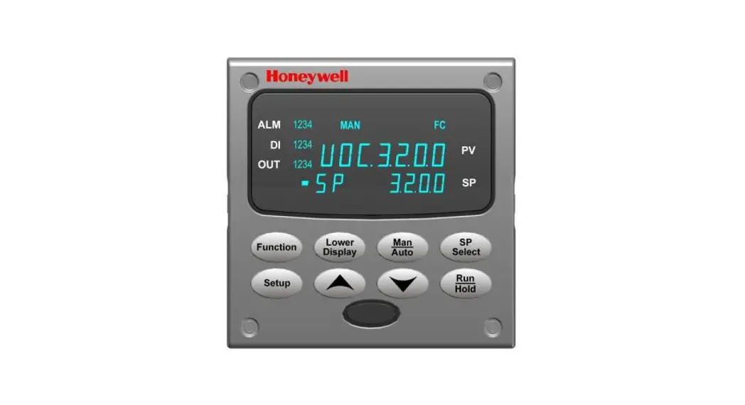
UDC3200 Universal Digital Controller
Model Selection Guide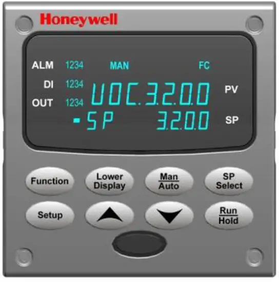 UDC3200 Controller
New! Easy To Use UDC3200 1/4 DIN Single Loop Controller
The UDC3200 Controller packs new powerful features while retaining all the simplicity and the flexibility of the industry-standard UDC3300 Controller. Many new optional features include:
– Enhanced Display
– Built-in infrared communications port for configuring with a Pocket PC or Laptop
– PC Based Configuration Tools
– Ethernet Communications
– Two Analog Inputs
– Accutane III, Fast/Slow, Heat/Cool
– Thermocouple Health Monitoring
Instructions
Select the desired key number. The arrow to the right marks the selection available. Make the desired selections from Tables I through VI using the column below the proper arrow. A dot ( ) denotes availability. KEY NUMBER – UDC3200 Single Loop Controller
| Description | |
| Digital Controller for use with 90 to 250Vac Power Digital Controller for use with 24Vac/dc Power | 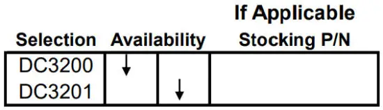 |
TABLE I – Specify Control Output and/or Alarms
| Output #1 | Current Output (4 to 20ma, 0 to 20 ma) Electro-Mechanical Relay (5 Amp Form C) Solid State Relay (1 Amp) Open Collector transistor output Dual 2 Amp Relays (Both are Form A) (Heat/Cool Applications) | 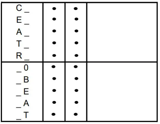 |
| Output #2 and Alarm #1 or Alarms 1 and 2 | No Additional Outputs or Alarms One Alarm Relay Only E-M Relay (5 Amp Form C) Plus Alarm 1 (5 Amp Form C Relay) Solid State Relay (1 Amp) Plus Alarm 1 (5 Amp Form C Relay) Open Collector Plus Alarm 1 (5 Amp Form C Relay) |
TABLE II – Communications and Software Selections
| Communications | None Auxiliary Output/Digital Inputs (1 Aux and 1 DI or 2 DI) RS-485 Modbus Plus Auxiliary Output/Digital Inputs 10 Base-T Ethernet (Modbus RTU) Plus Auxiliary Output/Digital Inputs | 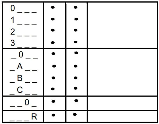 |
| Software Selections | Standard Functions, Includes Accutane Math Option Set Point Programming (1 Program, 12 Segments) Set Point Programming Plus Math | |
| Reserved | No Selection | |
| Infrared interface | Infrared Interface Included (Can be used with a Pocket PC) |
TABLE III – Input 1 can be changed in the field using external resistors
| Input 1 | TC, RTD, mV, 0-5V, 1-5V TC, RTD, mV, 0-5V, 1-5V, 0-20mA, 4-20mA TC, RTD, mV, 0-5V, 1-5V, 0-20mA, 4-20mA, 0-10V | 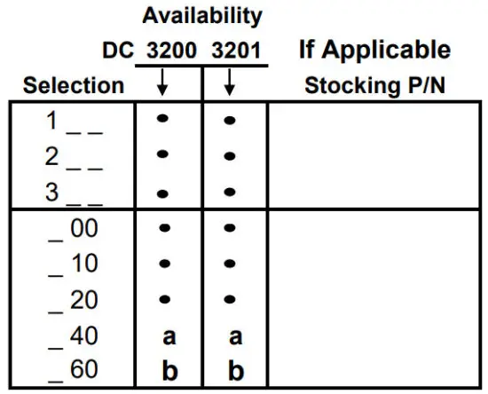 |
| Input 2 | None TC, RTD, mV, 0-5V, 1-5V, 0-20mA, 4-20mA TC, RTD, mV, 0-5V, 1-5V, 0-20mA, 4-20mA, 0-10V Slidewire Input for Position Proportional (Requires 2 Relay Outputs)Carbon, Oxygen, or Dewpoint (Provides 2 Inputs) |
TABLE IV – Options
| Approvals | CE (Standard) CE, UL, and CSA | 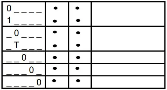 |
| one | None Stainless Steel Customer ID Tag – 3 lines w/22 characters/line | |
| Future Options | None | |
| None | ||
| None |
TABLE V – Product Manuals
| Manuals | Product Information on CD – All Languages English Manual French Manual German Manual Italian Manual Spanish Manual | 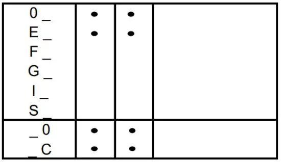 |
| Certificate | None Certificate of Conformance (F3391) |
TABLE VI
| No Selection | None |  |
ORDERING INSTRUCTIONS: These are provided as guidance for ordering such as those listed
- Part numbers are provided to facilitate Distributor Stock.
- Orders may be placed either by model selection or by part number.
- Part numbers are shown within the model selection tables to assist with compatibility information.
- Orders placed by model selection are systematically protected against incompatibility.
- Compatibility assessment is the responsibility of the purchaser for orders placed by part number.
- Items labeled as N/A are not available via the stocking program and must be ordered by model selection.
RESTRICTIONS
| Restriction Letters | Available Only With | Not Available With | ||
| Table | Selection | Table | Selection | |
| a | I | EE | ||
| I | AA | |||
| I | R | |||
| b | III | 1 | ||
Description | Part Number | |
| Bezel Assembly and Bezel Gasket | 51453143-502 | |
| Display/Keyboard (with IR) | 51452845-501 | |
| Power/Output PWA with 2 E-M Relays (90-264 Vac Operation) | 51452822-502 | |
| Power/Output PWA with 2 E-M Relays (24 Vac/dc Operation) | 51452822-503 | |
| Optional Analog Input PWA | 51452825-501 | |
| Auxiliary Output/Digital Input/RS-422/485 Communications PWA | 51452810-501 | |
| Auxiliary Output/Digital Input/Ethernet Communications PWA | 51452816-501 | |
| MCU/Inputs PWA | 51452819-501 | |
| Electro-Mechanical Relay | 30755306-501 | |
| Open Collector Output PWA | 30756679-501 | |
| Solid State Relay | 30756725-501 | |
| Current Output PWA | 51452804-501 | |
| Dual Electromechanical Relay PWA | 51452807-501 | |
| Ethernet Adaptor Board Kit | 50009071-501 | |
| Case Assembly (including Mounting Kit with four brackets) | 51452759-501 | |
| Varistor (MOV) 120 Vac | 30732481-501 | |
| Varistor (MOV) 240 Vac | 30732481-502 | |
| 4-20 mA Input Resistor Assembly (250 ohms) | 30731996-506 | |
| 0-10 Volt Input Resistor Assembly (100K pair) | 30754465-501 | |
| Mounting Kits (12 Brackets) | 51452763-501 | |
| DIN Adaptor Kit | 30755223-003 | |
| Process Instrument Explorer Software | 50001619-001 | |
| Math Software Upgrade | 50004635-501 | |
| SPP Software Upgrade | 50004635-502 | |
| Panel Bracket Kit | 50004821-501 | |
| Product Information on CD | All Languages | 51453375-501 |
| Quick Start Manual (2 page) Standard | English | 51-52-25-129 |
| Product Manual | English | 51-52-25-119 |
![]()


