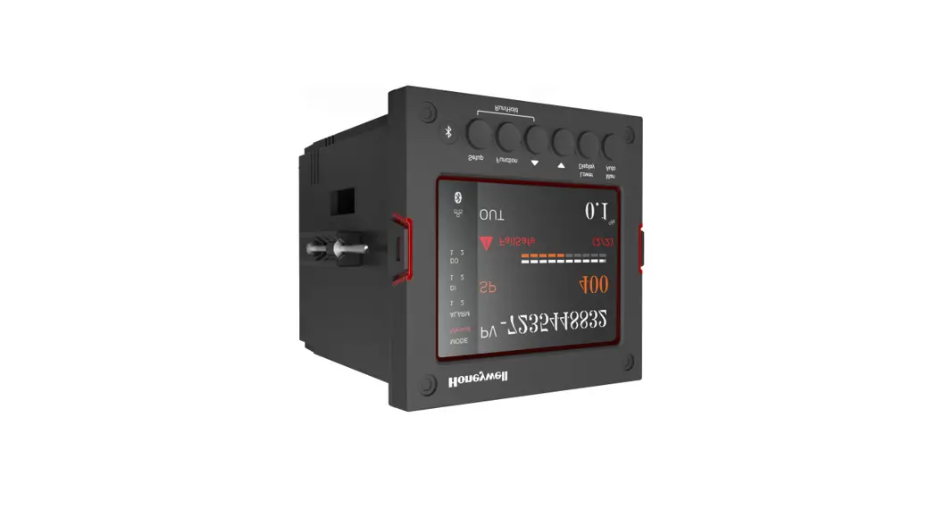
![]() UDC2800 Universal Digital Controller
UDC2800 Universal Digital Controller
User Guide
Getting started
When start up the controller for the first time, it is required to enter the initial password and a new password. The initial password is 1234.
Overview
This document is a quick start guide for UDC2800 controller. For detailed instructions, see UDC2800 Product Manual.
To Download the Product Manual:
- In a web browser, enter https://process.honeywell.com/us/en/support/product-documents-downloads, and login.
If you are a new user, register at this website first. - In the Search box, enter UDC2800 Product Manual (#51-52-25-157), and click the Search icon.
- Select DOCUMENT TYPE & PRODUCT filters, if required. The All search Results page appears with the search results.
- Click the package to download it.
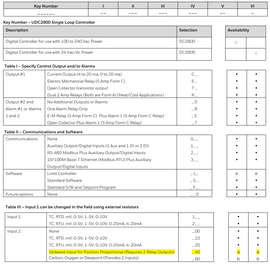
Model Number Interpretation
Write your controller’s model number in the spaces provided below and circle the corresponding items in each table. This information will also
be useful when you wire your controller.
- Select the desired Key Number. The arrow to the right marks the selection available.
- Make the desired selections from Table I to Table VI. A dot ‘·’ denotes availability.
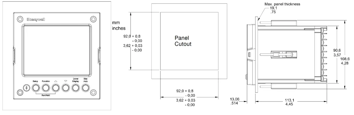
Dimensions and Mounting
Wiring
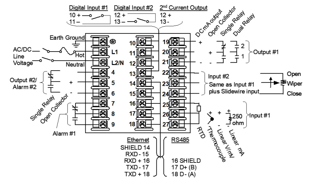
Attention: It is recommended to set up an uninterrupted power supply to avoid fluctuations on the device power line, as such fluctuations may cause device availability issues.
Configuration Procedure
| Step | Operation | Press | Result |
| Enter Set Up Mode | Setup key | Enter in the first set up group. Security. | |
| 2 | Select any Set Up group | Setup key or Increment or Decrement keys | Sequentially displays the other set up groups shown in the prompt hierarchy. See Configuration Record Sheet for prompts. You can also use the Increment or Decrement keys to scan the set up groups in both directions. Stop at the set up group tile that describes the group of parameters you want to configure. Then proceed to the next step. |
| 3 | Select a Function parameter | Function key | Enter in the first function prompt of the selected set up group. |
| Increment or Decrement keys | Press Increment or Decrement keys to display the other function prompts of the selected set up group. Stop at the function prompt that you want to change. | ||
| 4 | Change the Value or Selection | Function key | Enter in the value or selection of the selected function prompt. |
| Increment or Decrement keys | Increment or decrement the value or selection that appears for the selected function prompt You can press the Increment and Decrement keys at the same time to move the current editable digit one step left. | ||
| Enter the Value or Selection | Function key | Enter value or selection made into memory. | |
| 6 | Exit Configuration | Lower Display key | Exit the set up mode and returns to the main screen. |
Configuration Record Sheet
Enter the value or selection for each prompt on this sheet so you will have a record of how your controller was configured.
Group Prompt | Function Prompt | Value or Selection | Factory Setting | Group Prompt | Function Prompt | Value or Selection | Factory Setting |
| Security | Password Lockout Auto/Man Key Run/Hold Key SP Select Key Restore Settings Restore* Change Password | ―――― ―――― ―――― ―――― ―――― ―――― ―――― ―――― | 0 Calibration Enable Enable Enable Disable Disable – – | Accutune | Fuzzy Suppression Accutune Duplex Output Error Status | ―――― ―――― ―――― | Disable Disable Manual None |
| Tuning | Proportional Band 1 or Gain 1 or Rate Min Reset Mins/Rpt 1 or Reset Rpts/Min 1 Manual Reset Proportional Band 2 or Gain 2 Rate 2 Min Reset Mins/Rpt 2 or Reset Rpts/Min 2 Proportional Band 3 or Gain 3 Rate 3 Min Reset Mins/Rpt 3 or Reset Rpts/Min 3 Proportional Band 4 or Gain 4 Rate 4 Min Reset Mins/Rpt 4 or Reset Rpts/Min 4 Cycle Time 1 Sec Cycle Time 2 Sec | ―――― ―――― ―――― ―――― ―――― ―――― ―――― ―――― ―――― ―――― ―――― ―――― ―――― ―――― ―――― ―――― | 1.000 0.00 – – 0 1.000 0.00 1.00 1.000 0.00 1.0 1.000 0.00 1.00 – – 20 20 | SP Ramp/Program | SP Ramp Function Ramp Time Min Ramp Final SP SP Rate Function Rate Up EU/HRr Rate Down EU/Hr SP Program Function Soak Deviation Program Termination Program End State Key Reset/Rerun Hot Start | ―――― ―――― ―――― ―――― ―――― ―――― ―――― ―――― ―――― ―――― ―――― ―――― | Disable 3 1000 Disable 0 0 Disable 0 Last SP |
Start Up Procedure for Operation
It is required to enter the initial password and a new password when start up the controller for the first time. The initial password is 1234.
For more information of interface displays, see “Function of displays“ in UDC2800 Product Manual.
| Step | Operation | Press | Result |
| 1 | Select Manual Mode | Man Auto key | Until ‘Manual’ is displayed under MODE. The controller is in manual mode. |
| 2 | Adjust the Output | Increment or Decrement keys | Lower Display = OUT and the output value in Wo. To adjust the output value and ensure that the final control element is functioning correctly. |
| 3 | Enter the Local Setpoint | Lower Display key | Until the required ‘SP’ and the Local Setpoint Value are displayed. |
| 4 | Increment or Decrement keys | To adjust the local setpoint to the value at which you want the process variable maintained. Attention: The local setpoint 1 cannot be changed if the Setpoint Ramp function is running. | |
| 5 | Select Automatic Mode | Man Auto key | Until ‘Auto’ is displayed under MODE. The controller is in Automatic mode. The controller will automatically adjust the output to maintain the process variable at setpoint. |
| 6 | Tune the Controller | Setup key | Make sure the controller has been configured properly and all the values and selections have been recorded on the Configuration Record Sheet. Refer to Tuning Set Up group to ensure that the selections for Proportional Band or Gain, Rate Min, and Reset Mins/Rpt, or Reset Rpts/Min have been entered. Use Accutune to tune the controller. See ‘Accutune III’ in UDC2800 Product Manual. |
Setpoints
You can configure the following setpoints for the UDC2800 controller.
- A Single Local Setpoint
- 2 Local Setpoints
- 3 Local Setpoints
- 4 Local Setpoints
- Up to 4 Local Setpoints and 1 Remote Setpoint
Changing the Setpoint value
| Step | Operation | Press | Result |
| 1 | Select the Setpoint | Low Display key | Until you see: Lower Display = SP or 2SP or 3SP, or 4SP (Value) |
| 2 | Adjust the Output | Increment or Decrement keys | To change the Local Setpoint to the value at which you want the process maintained. The display -blinks” if you attempt to enter setpoint values beyond the high and low limits. The configured setpoint will be stored immediately. |
Switching between Setpoints
You can switch Local and Remote setpoints or between two Local setpoints when configured.
Attention: The Remote Setpoint value cannot be changed at the keyboard.
To switch between Setpoints
Press the Function key to switch the four Local Setpoints and/or the Remote Setpoint.
Attention: “KEY ERROR” appears if:
- the remote setpoint or additional local setpoints are not configured as a setpoint source.
- you attempt to change the setpoint while a setpoint ramp/program is running.
- you attempt to change the setpoint with the setpoint select function key disabled.
- while a setpoint ramp/program is not terminated.
Viewing the operating parameters
Under the main screen, press the Lower Display key to scroll through the operating parameters listed in table below. The lower display will show only those parameters and their values that apply to your specific model.
| Lower Display | Description |
| OUT XXX.X | Output value is shown in percent with one decimal point when Control Algorithm is NOT configured as Three Position Step Control (TPSC), and Slidewire is connected. |
| OUT XXX | Output value is shown in percent with no decimal point when Control Algorithm is NOT configured as Three Position Step Control (TPSC), Output Algorithm is configured as Position Proportion, and Slidewire fails. |
| COUT XXX.X | Appears when Shed function is Enabled, and Output Override register is successful override by Modbus (In Slave Mode) . |
| EOUT XXX.X | Appears when Shed function is Enabled, and the controller is in Slave Mode, push A/M key to enter Emergency Mode. |
| POS XXX | Slidewire Position – Used only with TPSC applications that use a slidewire input. |
| SP XXXX.XXX | Local Setpoint #1, appears when Control Algorithm is configured as ANY algorithm except Disable in the Algorithms set up group. It also appears for current setpoint when using SP Ramp. |
| 2SP XXXX.XXX | Local Setpoint #2, appears when the following two conditions are satisfied: • In the Algorithms set up group, configure Control Algorithm as ANY algorithm except Disable. • In the Control set up group, configure Local SP Source as 2/3/4 Local SPs. |
| 3SP XXXX.XXX | Local Setpoint #3, appears when the following two conditions are satisfied: • In the Algorithms set up group, configure Control Algorithm as ANY algorithm except Disable. • In the Control set up group, configure Local SP Source as 3/4 Local SPs. |
| 4SP XXXX.XXX | Local Setpoint #4, appears when the following two conditions are satisfied: • In the Algorithms set up group, configure Control Algorithm as ANY algorithm except Disable. • In the Control set up group, configure Local SP Source as 4 Local SPs. |
| RSP XXXX.XXX | Remote Setpoint, appears when the following two conditions are satisfied: • In the Algorithms set up group, configure Control Algorithm as ANY algorithm except Disable. • In the Control set up group, configure Remote SP Source as ANY selection except Disable. |
| CSP XXXX.XXX | Computer Setpoint, when SP is in override. • In the Algorithms set up group, configure Control Algorithm as ANY algorithm except Disable. • In the Communication set up group, enable Shed Function. And CSP is successfully override by SP override through Modbus. |
| SPN XXXX.XXX | Setpoint Now—Current Setpoint when SP Rate is enabled. The SP XXXX.XXX display shows the “target” or final setpoint value. SPN is not equal with the target SP. |
| DEV XXX.X | Deviation |
| 1 IN XXXX.XXX | Input 1—Used only with combinational input algorithms. |
| 2 IN XXXX.XXX | Input 2 |
| PID Set X | Tuning Parameter, where X is either 1, 2, 3 or 4. |
| BIAS XXXX | BIAS, displays the manual reset value for algorithm PD+MR. |
| AUX XXX.X | Auxiliary Output, displayed only when output algorithm is not Current Duplex. |
| TEL O XXH: XXM Or TEL O XXM: XXS | Elapsed Time, time that has elapsed on the Timer in Hours: Minutes, or Minutes: Seconds. The “O‘ is a clockwise running clock. |
| TRE O XXH: XXM Or TRE O XXM: XXS | Time Remaining, time remaining on the Timer in Hours: Minutes, or Minutes: Seconds. The “O” is a counter-clockwise running clock. |
| RAMP XXXM: XXS | Setpoint Ramp Time—Time remaining in the Setpoint Ramp in minutes. |
| PXSX RA XXH:XXM:XXS PXSX RA XXX/M (0~999) PXSX RA XXX/H (0~999) | Program X(1-8) Segment X(1-8) Ramp XXH:XXM:XXS remaining X and XX is current program or segment or time remaining Initial hold states Ramp time should be remaining time |
| PXSX SK XXH:XXM:XXS | Program X(1-8) Segment(1-8) Soak XXH:XXM:XXS remaining X and XX is current program or segment or time remaining Initial hold states Soak time should be remaining time |
| Recycle XX | Number of SP Program Recycles Remaining |
| To Begin | Reset SP Program to Start of First Segment |
| Rerun | Reset SP Program to Start of Current Segment |
| ACTU TUNE OFF | Limit Cycle Tuning not Running, appears when Accutune is enabled but not operating. |
| ACTU DO SLOW | Limit Cycle Tuning with the objective of producing damped or Dahlin tuning parameters, depending upon the detected process deadtime. The tuning parameters calculated by this selection are aimed at reducing PV overshoot of the SP setting. |
| ACTU DO FAST | Limit Cycle Tuning with the objective of producing quarter-damped tuning parameters. This tuning may result in PV overshoot of the SP setting. |
Notices
This document contains Honeywell proprietary information. Information contained herein is to be used solely for the purpose submitted, and no part of this document or its contents shall be reproduced, published, or disclosed to a third party without the express permission of Honeywell International Sàrl.
While this information is presented in good faith and believed to be accurate, Honeywell disclaims the implied warranties of merchantability and fitness for a purpose and makes no express warranties except as may be stated in its written agreement with and for its customer.
In no event is Honeywell liable to anyone for any direct, special, or consequential damages. The information and specifications in this document are subject to change without notice.
Copyright 2022 – Honeywell International Sàrl
Trademarks
Honeywell®, Experion®, PlantScape®, SafeBrowse®, and TotalPlant® are registered trademarks of Honeywell International, Inc.
Other brand or product names are trademarks of their respective owners.
Other trademarks
Microsoft and SQL Server are either registered trademarks or trademarks of Microsoft Corporation in the United States and/or other countries.
Trademarks that appear in this document are used only to the benefit of the trademark owner, with no intention of trademark infringement.
Third-party licenses
This product may contain or be derived from materials, including software, of third parties. The third party materials may be subject to licenses, notices, restrictions and obligations imposed by the licensor. The licenses, notices, restrictions and obligations, if any, may be found in the materials accompanying the product, in the documents or files accompanying such third party materials, in a file named third_party_ licenses on the media containing the product, or at http://www.honeywell.com/en-us/privacy-statement.
Support
For support, contact your local Honeywell Process Solutions Customer Contact Center (CCC). To find your local CCC visit the website,
https://www.honeywellprocess.com/en-US/contactus/customer-support-contacts/Pages/default.aspx.
How to report a security vulnerability
For the purpose of submission, a security vulnerability is defined as a software defect or weakness that can be exploited to reduce the operational or security capabilities of the software.
Honeywell investigates all reports of security vulnerabilities affecting Honeywell products and services.
To report a potential security vulnerability against any Honeywell product, please follow the instructions at: https://www.honeywell.com/enus/product-security.
Documentation feedback
You can find the most up-to-date documents on the Honeywell Process Solutions Support website at: www.honeywellprocess.com.
If you have comments about Honeywell Process Solutions documentation, send your feedback to: [email protected].
Use this email address to provide feedback, or to report errors and omissions in the documentation. For immediate help with a technical problem, contact HPS Technical Support through your local Customer Contact Center, or by raising a support request on the Honeywell Process Solutions Support website.
Training classes
Honeywell holds technical training classes that are taught by process control systems experts. For more information about these classes, contact your Honeywell representative, or see http://www.automationcollege.com.
Factory Information
Company Name: HONEYWELL System Sensor de Mexico, S. de R.L. de C.V .
Company Address: Avenida Miguel De La Madrid, #8102 Colonia Lote Bravo Ciudad Juarez, Chihuahua, C.P. 32695, México


