
EMERSON 1F85U-22PR Universal Thermostat
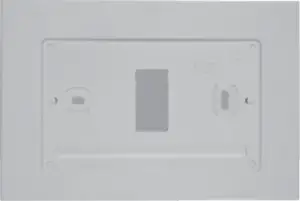 Optional Accessory: Wall Cover-Up Plate F61-2663, 6 3/4” W x 4 1/2” H Optional Accessory: Wall Cover-Up Plate F61-2663, 6 3/4” W x 4 1/2” H |
| Thermostat Applications | Maximum Stages Heat/ Cool |
| Conventional Gas, Oil, Electric (mV and 24V), Heat only, Cool only or Heat/Cool Systems | 2/2 |
| Heat Pump (Air Source or Geothermal) with Aux. Heat | 2/1 |
MERCURY NOTICE: This product does not contain mercury. However, this product may replace a product that contains mercury. Mercury and products containing mercury must not be discarded in household trash. |
SPECIFICATIONS
| Electrical Rating: | |||
| Battery Power | mV to 30 VAC, NEC Class II, 50/60 Hz | ||
| Input-Hardwire | 20 to 30 VAC, NEC Class II, 50/60 Hz | ||
| Terminal Load | 1.5 A per terminal, 2.5A maximum all terminals combined | ||
| Setpoint Range | 45° to 99° F (7° to 37° C) | ||
| Rated Differentials (@ 6°F/ Hr): | Fast | Med | Slow |
| Heat (Conventional Gas / Oil / Elect) | 0.5°F | 0.75°F | 1.9°F |
| Cool (Central Air) | 0.9°F | 1.2°F | 1.7°F |
| Heat Pump (Heat and Cool) | 0.9°F | 1.2°F | 1.7°F |
| Heat Pump Aux | 0.5°F | 0.75°F | 1.9°F |
| Operating Ambient | 32°F to +105°F (0° to +41°C) | ||
| Display Temperature Range | 32°F to +99°F (0 to 37°C) | ||
| Operating Humidity | 90% non-condensing maximum | ||
| Shipping Temperature Range | -20°F to + 150°F (-29° to +65°C) | ||
THERMOSTAT INSTALLATION
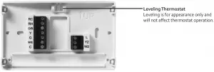
WIRING
Refer to equipment manufacturer’s instructions for specific system wiring information. After wiring, see INSTALLER MENU for proper thermostat configuration. Wiring table shown are for typical systems and describe the thermostat terminal functions. Wiring will change when dedicated emergency heat is on (See Installer Menu #15).
Terminal Designations | Terminal Function |
RC | Power (24V) – Cooling |
RH | Power (24V) – Heating |
O/B | Reversing Valve or output for 3 wire zone valves Configurable as “O” or “B” Reversing Valve or 3 wire zone heat (power close) |
Y | 1st Stage Compressor (conventional or heat pump) |
G | Fan Relay |
W/E | 1st Stage Heat (conventional); 1st Stage Auxiliary Heat (heat pump) Can operate as Emergency Heat only (See Installer Menu #15) |
C | Common wire for 24V (optional with batteries) |
L | Heat Pump Malfunction / Diagnostic terminal (input signal requires common) |
Y2 | 2nd Stage compressor (conventional only) |
W2 | 2nd Stage Heat (Conventional) Can operate as 1st Stage Auxiliary Heat (See Installer Menu #15) |
Precautions
- Do not exceed the specification ratings.
- All wiring must conform to local and national electrical codes and ordinances.
- This control is a precision instrument, and should be handled carefully. Rough handling or distorting components could cause the control to malfunction.
 |
Do not use on circuits exceeding specified voltage. Higher voltage will damage control and could cause shock or fire hazard. |
 |
To prevent electrical shock and/or equipment damage, disconnect electrical power to system, at main fuse or circuit breaker box, until installation is complete. |
|
To prevent compressor and/or property damage, if the outdoor temperature is below 50°F, DO NOT operate the cooling system. |
To prevent changes that may affect system performance, this thermostat has an INSTALLER MENU and a USER MENU. The INSTALLER MENU provides access to every option, while the USER MENU provides access to items that will not affect system performance. To access the INSTALLER MENU press the Menu button for 8 seconds. The display will show item 05 in the table below. Use Next and Back to navigate through menu items. Press ▲ or ▼ to change a menu setting.
Installer Menu # | Description | Default Setting (flashing icons) | Settings |
 | Outdoor Equipment: selects air conditioner (AC) or heat pump (HP ) equipment as well as the number of stage | AC2 | AC0 AC1 AC2 HP1 |
 | Indoor Equipment: selects whether the equipment is a gas furnace, electric furnace or fan only | EL2 | FAN GA1 GA2 (conventional only) EL1 EL2 (conventional only) |
 | Dedicated Emergency: W/E only operates in Emergency Aux mode. W2 becomes 1st stage Aux. Heat | OFF | On OFF |
 | O,B or 3 Wire Zone Valve Selection | 0 | O B 3 |
 | Fan Circulation Mode: Turns blower on for present time period when equipment has not cycled (on) for 1 hour | OFF | 10 minutes to 100 minutes in 5 minute increments |
 | Heat Cycle Rate: how often the heat will turn on | MEd | SLO – slow MEd – medium FAS – fast |
 | Aux Cycle Rate: how often the auxiliary heat will turn on | MEd | SLO – slow MEd – medium FAS – fast |
 | Cool Cycle Rate: how often the coo ling will turn on | MEd | SLO – slow MEd – medium FAS – fast |
 | Compressor Lockout: protects the compressor from short cycling | OFF | On – 5 minute delay OFF – no delay |
 | Ma x Heat Limit : maximum set point for heat mode | 99 | 47 to 99 |
 | Minimum Cool Limit : minimum set point for cool mode | 45 | 45 to 97 |
 | Schedule Type: set as either 7-Day, 5-1-1 Day or Non-Programmable | 5 | 7 – 7 Day 5 – 5-1-1 Day 0 – Non Programmable |
 | Defines periods per day | 4 | 2 -leave, return 4 -wake, leave, return, sleep |
 | Early Start: starts heating or cooling early so your programmed temperature is reached by the programmed time | OFF | On – start early OFF – start at program period time |
 | Fahrenheit or Celsius | °F | °F – Fahrenheit °C – Celsius |
 | Temperature Display Adjustment: adjust the displayed “Room Temperature” | 0 | -5 to +5 |
 | Continuous Display Light: keep the backlight always on – “C” wire required | OFF | On – always on OFF – momentarily |
 | Change Air Filter: set up a monthly reminder | OFF | 1 to 12 – reminder time (months) OFF – no filter reminder |
 | Auto Changeover: thermostat automatically switches between heat and cool | OFF | On – enable auto OFF – disable auto |
 | Keypad Lock: prevent unwanted changes to the thermostat | OFF | On – disable buttons OFF – all buttons are active |
TEST EQUIPMENT Turn on power to the system.
Fan Operation
If your system does not have a G terminal connection, skip to Heating System.
- Press the fan button to select the On position. The blower should begin to operate.
- Press the fan button to select the Auto position. The blower should stop immediately.
Heating System
- Press the System button to select the Heat position. Heat Pumps only – if the auxiliary heating system has a standing pilot, be sure to light it.
- Press ▲ to adjust thermostat setting to 1° above room temperature. The heating system should begin to operate and the thermostat will indicate Heat On.
- For heat pump with auxiliary- Press ▲ to adjust thermostat setting to 3° above room temperature. The auxiliary heat should begin to operate and the thermostat will indicate Heat On Aux.
- Press ▼ to adjust thermostat setting 1° below room temperature. The heating system should stop operating and the Heat On icon will disappear.
Auxiliary System ( only for heat pumps with auxiliary)
- Press the System button to select the Aux position.
- Press ▲ to adjust thermostat setting to 1° above room temperature. The auxiliary heating system should begin to operate and the thermostat will indicate Heat On Aux.
- Press ▼ to adjust thermostat setting 1° below room temperature. The auxiliary heating system should stop operating and the Heat On Aux icon will disappear.
Cooling System
- Press the System button to select the Cool position.
- Press ▼ to adjust thermostat setting 1° below room temperature. The blower should come on immediately on high speed, followed by cold air circulation. The thermostat will indicate Cool On. There can be up to a 5 minute delay. (see INSTALLER MENU, item 50)
- Press ▼ to adjust thermostat setting to 1° above room temperature. The cooling system should stop operating and the Cool On icon will disappear.
Note: If Starting Soon is shown on the display, the compressor lockout feature is operating. There will be up to a 5 minute delay before the compressor turns on (see INSTALLER MENU, item 50).
USING THE THERMOSTAT
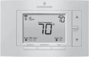
THERMOSTAT OVERVIEW
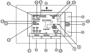
Before you begin using your thermostat, you should be familiar with its features, display and the location/operation of the thermostat buttons and switches.
| THERMOSTAT BUTTONS AND SWITCHES | THE DISPLAY |
| 1.) Fan Button | 8.) Next (Menu button) is used to navigate within a menu |
| 2.) Hold a permanent temperature or press again to cancel hold (return to programmed schedule) | 9.) Set the correct time, access the schedule and customize thermostat settings |
| 3.) System Button | 10.) Back (Fan button) is used to navigate within a menu |
| 4.) Backlight Button (located on the top of the thermostat) | 11.) Exit (Hold/Run button) returns to the home screen |
| 5.) Raises Temperature Setting | 12.) Thermostat is protecting the equipment from short cycling (5-minute delay) |
| 6.) Access Menu Options | 13.) Indicates that the system is running in Cool, Heat or Auxiliary mode. (Heat Pump Only -The auxiliary will run in Heat mode when the heat pump cannot maintain the set temperature.) |
| 7.) Lowers Temperature Setting | 14.) SEE TROUBLESHOOTING |
| 15.) Battery status indicator | |
| 16.) Replace battery indicator | |
| 17.) Day of the week used when programming a schedule | |
| 18.) Permanent hold (bypassing the schedule) | |
| 19.) Temperature setpoint | |
| 20.) Appears when the keypad is locked (to prevent unwanted changes) |
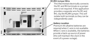
Whenever”![]() ” appears in the display, new premium brand AA alkaline batteries should be installed. If the house will be unoccupied for an extended period and either “
” appears in the display, new premium brand AA alkaline batteries should be installed. If the house will be unoccupied for an extended period and either “![]() ” or “
” or “ ![]() ” is displayed, install new batteries before leaving.
” is displayed, install new batteries before leaving.
To customize thermostat settings, press and hold the Menu button for ½ second from the home screen. Use the ▲ or ▼ buttons to highlight Settings and press Next. Use Next and Back to navigate through menu items. Press ▲ or ▼ to change the setting.
| User’s Menu # (Press Menu button and release) | Description | Default Setting (flashing icons) | Settings (Press ▲or▼) |
 | Schedule Type: set as either 7-Day, 5-1-1 Day or Non Programmable | 5 | 7 – 7 Day 5 – 5-1-1 Day 0 – Non-Programmable |
 | Defines periods per day | 4 | 2 – leave, return 4 – wake, leave, return, sleep |
 | Early Start: starts heating or cooling early so your programmed temperature is reached by the programmed time | OFF | On – start early OFF – start at program period time |
 | Fan Circulation Mode: Turns blower on for present time period when equipment has not cycled (on) for 1 hour | OFF | 10 minutes to 100 minutes in 5 minute increments |
 | Continuous Display Light: keep the backlight always on – “C” wire required | OFF | On – always on OFF – momentarily |
 | Change Air Filter: set up a monthly reminder | OFF | 1 to 12 – reminder time (months) OFF – no filter reminder |
 | Auto-Changeover: thermostat automatically switches between heat and cool | OFF | On – enable auto| OFF – disable auto |
THERMOSTAT OPERATION
Set Current Time and Day
Note: Time icons will flash at initial power up or after a reset.
- Press Menu
- The time icon will be flashing. Press Next to advance and set the time
- Use ▲ or ▼ to set the correct time
- Press Next and use ▲ or ▼ to set the correct day
- Press Exit when finished.
The default program is 5-1-1 Day, but can be setup as a 7-Day or Non-Programmable thermostat (refer to the User Menu above).
- Hold Temperature (bypassing the schedule) – With the System set to Heat or Cool, momentarily press the Hold/Run button. Hold will be displayed. Use ▲ or ▼ to adjust the temperature. The thermostat will hold the room temperature at the selected setting until you press Hold/Run again to start program operation (cancels permanent Hold).
- Program Override (Temporary Hold) – Press ▲ or ▼ until the desired temperature is displayed. The thermostat will override the schedule until the next programmed time period with a minimum override of 2 hours. Then the thermostat will automatically revert to the program.
- Keypad Lockout – To prevent unwanted changes, the buttons can be disabled.
To turn this feature On, press and hold ▲ and the Menu button until the icon appears. To turn Off, press and hold ▲ and the Menu button for 3 seconds.
THERMOSTAT SCHEDULE / PROGRAMMING
Energy Saving Factory Schedule
This thermostat is programmed with the energy saving settings shown in the table below for all days of the week

Energy Saving Factory Schedule
This thermostat is programmed with the energy saving settings shown in the table below for all days of the week.
| P1 / Wake | P2 / Leave | P3 / Return | P4 / Sleep | |
| Heating Schedule | 6:00 AM – 70°F | 8:00 AM – 62°F | 5:00 PM – 70°F | 10:00 PM – 62°F |
| Cooling Schedule | 6:00 AM – 78°F | 8:00 AM – 85°F | 5:00 PM – 78°F | 10:00 PM – 82°F |
Note: Thermostat can be programmed on or off the subbase
Modify the Heating Schedule
- Use the System button to select Heat
- Press Menu
- Use the ▼ button to select Schedule and press Next to enter the schedule
- The time icons will flash – use ▲ or ▼ to set the time for the start of a period
- Press Next – the set point icons will flash – use ▲ or ▼ to set the temperature for the current period
- Continue to press Next to advance through all periods (P1 / Wake, P2 / Leave, P3 / Return, P4 / Sleep) for all days of the week.
Note: Press Back to return to the previous setting. Once all days of the week have been programmed the thermostat will display End. Press Exit at any time to save changes and return to home screen.
Modify the Cooling Schedule
- Use the System button to select Cool
- Repeat steps 2-6 from the heating schedule
TROUBLESHOOTING
| Symptom | Possible Cause | Corrective Action |
| No Heat/ No Cool/ No Fan (common problem) |
|
|
| No Heat |
|
|
| No Cool |
|
|
| Heat, Cool or Fan Runs Constantly | Possible short in wiring, thermostat, heat, cool or fan system | Check each wire connection to verify they are not shorted or touching other wires. Try resetting the thermostat. If the condition persists contact your HVAC service person. |
| Thermostat Display & Thermometer Disagree | Thermostat display requires adjustment | Display can be adjusted +/-5°. See User Menu item 05 |
| Furnace (Air Conditioner) Cycles Too Fast or Slow (narrow or wide temperature swing) | The location of the thermostat and/or the size of the Heating System may be influencing the cycle rate | Digital thermostats provide precise control and cycle faster than older mechanical models. The system turns on and off more frequently, but runs for a shorter time. If you would like to increase cycle time, choose SLO for slow cycle in the Installer menu. (Reference menu items 30, 32 & 35.) If an acceptable cycle rate is not achieved, contact your HVAC service person. |
| “Call for Service” icon appears on displayed |
|
|
Resetting the Thermostat or Thermostat Settings
If the thermostat has good batteries, but has a blank display or does not respond to key presses, the thermostat should be reset by removing the batteries for 2 minutes. This reset will not change the menu settings or program. If the condition persists after reinstalling the batteries, replace the thermostat.
To conveniently reset only the schedule and user settings back to factory defaults, press Menu and Backlight buttons at the same time and hold until the display goes blank and resets.
| WARNING: This product contains a chemical known to the state of California to cause cancer and birth defects and other reproductive harm. |
| HOMEOWNER HELP LINE: 1-800-284-2925 |

Emerson and White-Rodgers are trademarks of Emerson Electric Co.
©2020 Emerson Electric Co.
All rights reserved.


