AIMCO AEP4A771200B AcraDyne High-Torque DC Nutrunne
Introduction
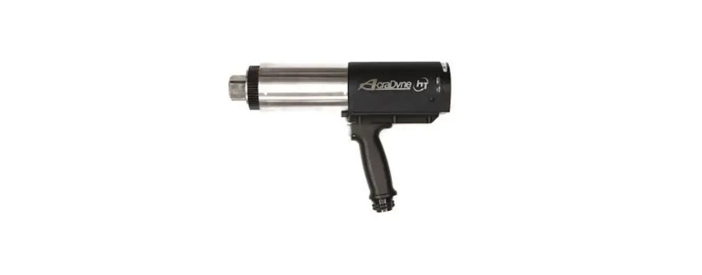
Thank you for your purchase of an AcraDyne® HT Series Electric Transducerized Nutrunner. These Nutrunners deliver true, traceable Torque and Angle tightening events with data recording abilities delivered by the connected AcraDyne Controllers.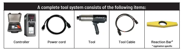
Safety Information
CAUTION – DO NOT USE THE ACRADYNE® HT NUTRUNNING SYSTEM WITHOUT FULLY READING THIS MANUAL AND HAVING A COMPLETE UNDERSTANDING OF THE CORRECT USAGE OF A HIGH TORQUE DELIVERING TOOL AND ANY ASSOCIATED REACTION BARS/ACCESSORIES.
SAVE THESE INSTRUCTIONS
WORK AREA
- Keep work area clean and well lit. Cluttered and dark areas invite accidents.
- Do not operate power tools in explosive atmospheres, such as the presence of flammable liquids, gases or dust. Power tools create sparks which may ignite the dust or fumes.
- Keep children and bystanders away while operating a power tool. Distractions can cause you to lose control.
ELECTRICAL SAFETY
- Power tool plugs must match the outlet. Never modify the plug in any way. Do not use any adapter plugs with earthed (grounded) power tools. Unmodified plugs and matching outlets will reduce risk of electric shock.
- Avoid body contact with earthed or grounded surfaces such as pipes, radiators, ranges and refrigerators. There is an increased risk of electric shock if your body is earthed or grounded.
- Do not expose power tools to rain or wet conditions. Water entering a power tool will increase the risk of electric shock.
- Do not abuse the cord. Never use the cord for carrying, pulling or unplugging the power tool. Keep cord away from heat, oil, sharp edges or moving parts. Damaged or entangled cords increase the risk of electric shock.
PERSONAL SAFETY
Indicates Caution is required. Failure to exercise caution and correct operating technique can result in serious personal injury, loss of limb or death.
- Stay alert, watch what you are doing and use common sense when operating a power tool. Do not use a power tool while you are tired or under the influence of drugs, alcohol or medication. A moment of inattention while operating power tools may result in serious personal injury.
- Use safety equipment. Always wear eye protection. Safety equipment such as dust mask, non-skid safety shoes, hard hat, or hearing protection used for appropriate conditions will reduce personal injuries. If the maximum duty cycle of the attached tool is exceeded or the tool temperature exceeds 50° C., then the operator should wear protective hand wear (gloves).
- Avoid accidental starting. Ensure the switch is in the off-position before plugging in. Carrying power tools with your finger on the switch or plugging in power tools that have the switch on invites accidents.
- Remove any adjusting key or wrench before turning the power tool on. A wrench or a key left attached to a rotating part of the power tool may result in personal injury.
- Do not overreach. Keep proper footing and balance at all times. This enables better control of the power tool in unexpected situations.
- Dress properly. Do not wear loose clothing or jewelry. Keep your hair, clothing and gloves away from moving parts. Loose clothes, jewelry or long hair can be caught in moving parts.
- If devices are provided for the connection of dust extraction and collection facilities, ensure these are connected and properly used. Use of these devices can reduce dust-related hazards.
POWER TOOL USE AND CARE
- Do not force the power tool. Use the correct power tool for your application. The correct power tool will do the job better and safer at the rate for which it was designed.
- Do not use the power tool if the switch does not turn it on and off. Any power tool that cannot be controlled with the switch is dangerous and must be repaired.
- This product is designed to be used in combination with the AcraDyne iEC DC tool controller for intermittent hand-held or fixtured assembly processes.
Environmental & Electrical Specifications
Environmental
- Operating Temperature: 0°C to 32°C
- Storage Temperature: 0°C to 65°C
- Humidity:
- – 5% to 90% RH, Non-Condensing, for temperatures 0°C to 40°C
- – 5% to 60% RH, Non-Condensing, for temperatures 0°C to 65°C
- Maximum Altitude of Operation: 3000m
- Maximum decibel level: 77 dB(A)
Electrical
- Motor Type: BLDC
- – Motor Phase Voltage: 320 Volts Pulse DC @
- Controller Supply Voltage of 120 RMS, or 320 Volts
- Pulse DC @ Controller Supply Voltage of 230 RMS
- Duty Cycle: The Nutrunners are intended for intermittent operation with recommended duty cycles not to exceed 30%. Note: Actual maximum duty cycles are dependent upon several factors including: Ambient Temperature, Tool Selection, Joint Conditions, Operating Parameter Set Programming and Operator Handling.
For optimum Duty Cycle determination, please contact your authorized AcraDyne® Product Representative. - Motor Speed Setting Guidelines – All settings of AcraDyne HT Series Nutrunners should be made only by experienced, well-trained technicians. Tools with maximum RPM ratings of 25 RPM or lower should be set to run at the tool’s maximum rated speed. Specific application demands may require additional stages to achieve optimal results. Consult the appropriate AcraDyne Tool Controller manual for guidelines and specific information related to programming procedures and techniques.
If attempting to use tooling below 0°C, allow the system to warm up by running in a no-load state until acceptable temperatures are reached.
Tool Specifications
Fixed Gearcase HT Tools
HT Fixed Gearcase Tools
|
Model | Approx. Torque | Approx. Speed | Weight | Total Length (incl sq. dr) | Dia. | Drive | Sound Level | |||||
| NM | FT-LB | RPM | KG | LB | MM | IN | MM | IN | IN | dB(A) | ||
| HT Series Fixed Gearcase Models (R) = Pistol Tool with Rear Exit Cable (B) = Fixtured Model with Bottom Exit Cable | ||||||||||||
| 6000 Series | ||||||||||||
| AE (P) 4A66250B (R) | 250 | 185 | 315 | 4.6 | 10.5 | 66 | 2.6 | 0.75 | 66 | |||
| AE (D) (S) (J) (F) 4A66250B | P = 289 P(R) = 331 D = 388 S = 440 J = 331 F = 331 F(B) = 353 | 11.4 13 15.3 17.3 13 13 13.9 | ||||||||||
| AE (P) 4A66425B (R) | 165 | 0.75 | 66 | |||||||||
| AE (D) (S) (J) 4A66425B | 425 | 315 | 4.6 | 10.5 | 66 | 2.6 | ||||||
| AE (F) 4A66425B (B) | ||||||||||||
| AE (P) A66625B (R) | 106 | 0.75 | 66 | |||||||||
| AE (D) (S) (J) 4A66625B | 625 | 460 | 4.8 | 10.5 | 66 | 2.6 | ||||||
| AE (F) 4A66625B (B) | ||||||||||||
| AE (P) 4A66925B (R) | 925 | 682 | 72 | 4.8 | 10.5 | 66 | 2.6 | 0.75 | 66 | |||
| AE (D) (S) (J) (F) 4A66925B | ||||||||||||
| 7000 Series | ||||||||||||
| AE (F) 4A76200BB | 200 | 148 | 432 | 5.2 | 11.5 | 313 | 1 | 2.3 | 67.3 | 2.7 | 0.75 | 66 |
| AE (P) (D) (S) (J) 4A771200B | 1,200 | 885 | 65 | 6.6 | 14.5 | P = 302 D = 301 S = 302 J = 343 F = 343 | 11.9 11.9 11.9 13.5 13.5 | 77.5 | 3.1 | 1 | 66 | |
| AE (F) 4A771200B (B) | ||||||||||||
| AE (P) (D) (S) (J) 4A773000B | 3,000 | 2,213 | 25 | 7.5 | 16.5 | P = 337 D = 337 S = 337 J = 379 F = 379 | 13.3 13.3 13.3 14.9 14.9 | 77.5 | 3.1 | 1 | 66 | |
| AE (F) 4A773000B (B) | ||||||||||||
| 8000 Series | ||||||||||||
| AE (P) (D) (J) (F) 4A884200B1 | 4,200 | 3,100 | 12 | 11.1 | 24.5 | P = 384 D = 480 S = 546 J = 410 F = 410 | 15.1 18.9 21.5 16.1 16.1 | B1 = 1 | 66 | |||
| AE (P) (D) (S) (J) (F) 4A884200B | B = 1.5 | |||||||||||
| AE (P) (D) (J) (F) 4A885000B | 5,000 | 3,700 | 9.3 | 11.1 | 24.5 | 91.2 | 3.6 | 1.5 | 66 | |||
| AE (P) (D) (J) (F) 4A896500B | 6,500 | 4,800 | 7 | 15.7 | 34.5 | P = 438 D = 533 S = 599 J = 463 F = 462 | 17.2 21 23.6 18.2 18.2 | 1.5 | 66 | |||
| AE (F) 4A896500B (B) | ||||||||||||
| AE (P) (D) (S) (J) (F) 4A898100B | 8,100 | 6,000 | 5 | 15.7 | 34.5 | 103.8 | 4.1 | |||||
* 8,100 Nm – 17,000 Nm models are not supported by the Gen III controller platform. The Gen IV controller platform is required.
360° Swivel Gearcase HT Tools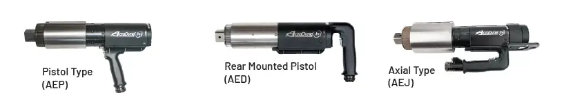
HT 360° Swivel Gearcase Tools
| Approx. Torque | Approx. Speed | Weight | Length (incl sq. dr) | Dia. | Drive | Sound Level | |||||
| Model | NM | FT-LB | RPM | KG | LB | MM | IN | MM | IN | IN | dB(A) |
| HT Series 360° Swivel Gearcase Models (R) = Pistol Tool with Rear Exit Cable | |||||||||||
| 6000 Series | |||||||||||
| AE (P) 4B66250B(R) | 250 | 185 | 315 | 5.3 | 12 | 0.75 | 66 | ||||
| AE (D) (J) 4B66250B | |||||||||||
| AE (P) 4B66425B(R) | 425 | 315 | 165 | 5.3 | 12 | P = 327 P(R) = 368 D = 429 J = 369 | 12.9 14.5 16.9 14.5 | 0.75 | 66 | ||
| AE (D) (J) 4B66425B | 67.3 | 2.7 | |||||||||
| AE (P) 4B66625B(R) | 625 | 460 | 106 | 5.5 | 12 | 0.75 | 66 | ||||
| AE (D) (J) 4B66625B | |||||||||||
| AE (P) 4B66925B(R) | 925 | 682 | 72 | 5.5 | 12 | 0.75 | 66 | ||||
| AE (D) (J) 4B66925B | |||||||||||
| 7000 Series | |||||||||||
| AE (P) (J) 4B771200B | 1 ,200 | 885 | 65 | 7.3 | 16 | P = 339 J = 381 | 13.4 15 | 77.5 | 3.1 | 1 | 66 |
| AE (P) (J) 4B773000B | 3,000 | 2,213 | 25 | 8.2 | 18 | ||||||
| 8000 Series | |||||||||||
| AE (P) (D) (J) 4B884200B1 | 4,200 | 3,100 | 12 | 11.8 | 26 | P = 422 D = 518 J = 446 | 16.6 20.4 17.6 | 91.2 | 3.6 | B1 = 1 | 66 |
| AE (P) (D) (J) 4B884200B | B = 1.5 | ||||||||||
| AE (P) (J) 4B896500B | 6,500 | 4,800 | 7 | 16.4 | 36 | P = 475 J = 499 | 18.7 19.7 | 103.8 | 4.1 | 1.5 | 66 |
| AE (P) (D) (J) 4B898100B* | 8,100 | 6,000 | 5 | 16.4 | 36 | P = 475 D = 571 J = 499 | 18.7 22.5 19.7 | 103.8 | 4.1 | 1.5 | 66 |
| AE (P) 4B998100B* | 8,100 | 6,000 | 5 | 21.8 | 48 | 532 | 20.9 | 112 | 4.4 | 1.5 | 66 |
| Models for Extreme Duty / Low Power Environments | |||||||||||
| AE (P) (J) 4W872800B | 2,800 | 2,065 | 9 | 10.0 | 22 | P = 406 J = 430 | 16 17 | 76 | 3.0 | 1 | 66 |
| AE (P) (D) (J) 4W885000B1* | 5,000 | 3,700 | 4.5 | 11.8 | 26 | P = 422 D = 518 J = 446 | 16.6 20.4 17.6 | 91.2 | 3.6 | B1 = 1 | 66 |
| AE (P) (D) (J) 4W885000B* | B = 1.5 |
* 8,100 Nm – 17,000 Nm models are not supported by the Gen III controller platform. The Gen IV controller platform is required.
Dual-Lever Fixed Gearcase HT Tools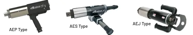
HT Fixed Gearcase Dual-Lever Tools
| Dual Lever | Approx. Torque | Approx. Speed | Weight | Length (incl sq. dr) | Dia. | Drive | Sound Level | ||||
| Model | NM | FT-LB | RPM | KG | LB | MM | IN | MM | IN | IN | dB(A) |
| HT Series Fixed Gearcase: Dual-Lever Models For Straight Type Tools Only: (L) = Left-Side Handle (R) = Right-Side Handle | |||||||||||
| 6000 Series | |||||||||||
| AE (P) (F) 4A66250BDL | 250 | 185 | 315 | 3.9 | 9 | 0.75 | 66 | ||||
| AE (S) 4A66250BDL (L) (R) | |||||||||||
| AE (P) (F) 4A66425BDL | 425 | 315 | 165 | 3.9 | 9 | P = 314 F = 331 S = 440 | 12.4 13 17.3 | 0.75 | 66 | ||
| AE (S) 4A66425BDL (L) (R) | 67.3 | 2.7 | |||||||||
| AE (P) (F) 4A66625BDL | 625 | 460 | 106 | 4.1 | 9 | 0.75 | 66 | ||||
| AE (S) 4A66625BDL (L) (R) | |||||||||||
| AE (P) (F) 4A66925BDL | 925 | 682 | 72 | 4.1 | 9 | 0.75 | 66 | ||||
| AE (S) 4A66925BDL (L) (R) | |||||||||||
| 7000 Series | |||||||||||
| AE (P) (F) 4A771200BDL | 1,200 | 885 | 65 | 5.9 | 13 | P = 324 F = 343 S = 453 | 12.7 13.5 17.8 | 77.5 | 3.1 | 1 | 66 |
| AE (S) 4A771200BDL (L) (R) | |||||||||||
| AE (P) (F) 4A773000BDL | 3,000 | 2,213 | 25 | 6.8 | 15 | P = 359 F = 379 S = 488 | 14.1 14.9 19.2 | 77.5 | 3.1 | 1 | 66 |
| AE (S) 4A773000BDL (L) (R) | |||||||||||
| 8000 Series | |||||||||||
| AE (F) 4A884200B1DL | 4,200 | 3,100 | 12 | 10.4 | 23 | 410 | 16.1 | 91.2 | 3.6 | B1 = 1 | 66 |
| AE (F) 4A884200BDL | B = 1.5 | ||||||||||
| AE (F) 4A885000BDL | 5,000 | 3,700 | 9.3 | 10.4 | 23 | 410 | 16.1 | 91.2 | 3.6 | 1 | 66 |
| AE (P) (F) 4A896500BDL | 6,500 | 4,800 | 7 | 15.0 | 33 | P = 438 F = 462 | 17.2 18.2 | 102.4 | 4 | 1.5 | 66 |
| AE (F) (J) 4A898100BDL* | 8,100 | 6,000 | 5 | 15.0 | 33 | F = 462 J = 462 | 18.2 18.2 | 102.4 | 4 | 1.5 | 66 |
* 8,100 Nm – 17,000 Nm models are not supported by the Gen III controller platform. The Gen IV controller platform is required.
Dual-Lever 360° Swivel Gearcase HT Tools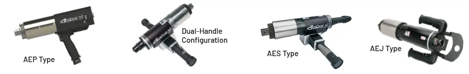
HT 360° Swivel Gearcase Dual-Lever Tools
| Dual Lever | Approx. Torque | Approx. Speed | Weight | Length (incl sq. dr) | Dia. | Drive | Sound Level | ||||
| Model | NM | FT-LB | RPM | KG | LB | MM | IN | MM | IN | IN | dB(A) |
| HT Series 360° Swivel Gearcase: Dual-Lever Models For Straight Type Tools Only: (L) = Left-Side Handle (R) = Right-Side Handle | |||||||||||
| 6000 Series | |||||||||||
| AE (P) (F) 4B66250BDL | 250 | 185 | 315 | 4.6 | 10.5 |
0.75 | 66 | ||||
| AE (S) 4B66250BDL (L) (R) | |||||||||||
| AE (F) 4B66425BDL | 425 | 315 | 165 | 4.6 | 10.5 | P = 353 F = 369 S = 630 | 13.9 14.5 24.8 | 66 | |||
| AE (S) 4B66425BDL (L) (R) | 67.3 | 2.7 | |||||||||
| AE (F) 4B66625BDL | 625 | 460 | 106 | 4.8 | 10.5 | 66 | |||||
| AE (S) 4B66625BDL (L) (R) | |||||||||||
| AE (F) 4B66925BDL | 925 | 682 | 72 | 4.8 | 10.5 | 66 | |||||
| AE (S) 4B66925BDL (L) (R) | |||||||||||
| 7000 Series | |||||||||||
| AE (P) (F) 4B771200BDL | 1,200 | 885 | 65 | 6.6 | 14.5 | P = 361 F = 382 S = 492 | 14.2 15 19.4 | 77.5 | 3.1 | 1 | 66 |
| AE (S) 4B771200BDL (L) (R) | |||||||||||
| AE (D) 4B771800BDL (L) | 1,800 | 1,328 | 28 | 7.5 | 16.5 | 475 | 18.7 | 77.5 | 3.1 | 1 | 66 |
| AE (P) (F) 4B773000BDL | 3,000 | 2,213 | 25 | 7.5 | 16.5 | P = 398 F = 418 S = 528 | 15.7 16.5 20.8 | 77.5 | 3.1 | 1 | 66 |
| AE (S) 4B773000BDL (L) (R) | |||||||||||
| 8000 Series | |||||||||||
| AE (P) (F) 4B896500BDL | 6,500 | 4,800 | 5 | 16.4 | 36 | P = 475 F = 499 | 18.7 19.7 | 104 | 4.1 | 1.5 | 66 |
| AE (J) 4B898100BDL* | 8,100 | 6,000 | 5 | 16.4 | 36 | 499 | 19.7 | 104 | 4.1 | 1.5 | 66 |
* 8,100 Nm – 17,000 Nm models are not supported by the Gen III controller platform. The Gen IV controller platform is required.
HTXD Extreme Duty High Torque Tools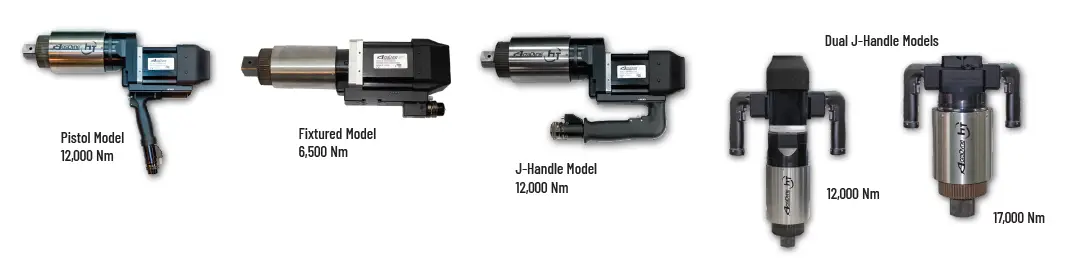
* Weight is tool only w/o Socket and Reaction Bar
HT 360° Swivel Gearcase Bolting Tools for Extreme Duty
| AEF4A996500B | 9000 | 6,500 | 4,800 | 5.8 | 19 | 42 | 494 | 19.5 | 104 | 4.1 | 1.5 | 66 |
| AEP4W998100B | 9000 | 8,100 | 6,000 | 2.3 | 21.8 | 48 | 544 | 21.4 | 104 | 4.1 | 1.5 | 66 |
| AEJ4W998100B | 9000 | 8,100 | 6,000 | 2.3 | 21.8 | 48 | 544 | 21.4 | 104 | 4.1 | 1.5 | 66 |
| AEJ4U998100BDL | 9000 | 8,100 | 6,000 | 2.3 | 21.8 | 48 | 427 | 16.8 | 104 | 4.1 | 1.5 | 66 |
| AEP4W9X12000B | 9X | 12,000 | 8,850 | 2 | 31.8 | 70 | 572 | 22.5 | 131 | 5.2 | 1.5 | 66 |
| AEJ4W9X12000B | 9X | 12,000 | 8,850 | 2 | 31.8 | 70 | 572 | 22.5 | 131 | 5.2 | 1.5 | 66 |
| AEJ4U9X12000BDL | 9X | 12,000 | 8,850 | 2 | 31.8 | 70 | 441 | 17.4 | 131 | 5.2 | 1.5 | 66 |
| AEP4W9Y17000B | 9Y | 17,000 | 12,500 | 1 | 42.6 | 94 | 381 | 15 | 153 | 6.0 | 2.5 | 66 |
| AEJ4W9Y17000B | 9Y | 17,000 | 12,500 | 1 | 42.6 | 94 | 381 | 15 | 153 | 6.0 | 2.5 | 66 |
| AEJ4U9Y17000BDL | 9Y | 17,000 | 12,500 | 1 | 42.6 | 94 | 458 | 18 | 153 | 60 | 2.5 | 66 |
Operation
CAUTION IS REQUIRED. FAILURE TO EXERCISE CAUTION AND CORRECT OPERATING TECHNIQUE CAN RESULT IN SERIOUS PERSONAL INJURY, LOSS OF LIMB OR DEATH.
AcraDyne® HT Series Nutrunners are a part of a complete system including Controller, Tool Cable and Tool. Specific instructions on setup, programming and features are described in greater detail within the AcraDyne® Controller Manuals and ToolWare software manuals that are provided with those components.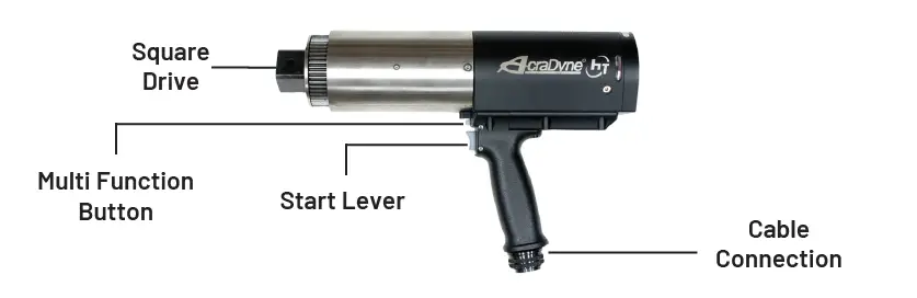
Make sure that power is not turned on at the controller before making any connections to tool.
Connect the tool cable to the iEC controller and the tool: \
The tool cable has curved alignment tabs and slots built into the connectors at each end to ensure proper alignment and connection with the tool and controller. Align the female connector on the cable with the male connector on the tool and insert the cable onto the tool, then slide the connector nut onto the threads on the cable and turn clockwise until hand-tight.
Align the male connector tab on the other end of the tool cable with the female slot on the controller and insert the cable into the connector, then slide the metal outer cover onto the connection
threads on the controller and turn clockwise until hand-tight.
Multifunction Button Operation:
The tool will flash all LED lights three times when power is first turned on at the controller. After the controller finishes initializing and displays a target torque value, the multifunction button (MFB) is used to toggle the tool from clockwise mode (FWD) to counter-clockwise operation mode (REV). The MFB is the small button opposite the trigger. The MFB is user configurable in the controller software so this applies to factory default settings only. The tool will initially start in clockwise mode and will have no LED lights turned on. If the trigger is pressed, the tool will turn on the blue LED once In Cycle Torque is reached meaning the tightening operation is underway. Pressing the MFB will cause all tool LED lights to flash. Pressing the MFB again will switch the tool back to FWD mode and will indicate this with no LED lights turned on (factory default setting). For further functionality, see the AcraDyne iEC controller manual.
Start Lever Operation:
To start the tool, depress the start lever. Blue LED lights will be displayed while tightening a bolt once In Cycle Torque is reached. The tool will stop automatically when it senses its target torque value or if no torque is sensed in a specified time period. After a cycle is complete, the tool will display green LED lights for a success, or red LED lights for failure to reach torque/angle. Previous cycle result will remain lit until a new cycle is started and surpasses In Cycle Torque setting.
Free Run Timeout (Controller Program Setting):
For tools with Catalog rated speeds below 60 RPM, it is recommended that the Free Run Timeout in the Controller DSP menu under Timeout Settings be changed to 30 seconds from the default setting of 5 seconds.
Light Ring Light Assignment
| Light Color | Meaning |
| Green Solid | OK |
| Red Flashing | Torque Low |
| Red Solid | Torque High |
| Yellow Flashing | Angle Low |
| Yellow Solid | Angle High |
| Blue Solid | Tool In-Cycle/Tool Armed |
| Blue Flashing | P-Set Change thru MFB |
| All On Flashing | Tool in Disassembly |
| Buzzer | Bad Assembly/Tool in Disassembly/Power Up |
The Buzzer and Multi-Function Button are programmable in the DSP Menu of ToolWare.
Slip Ring Models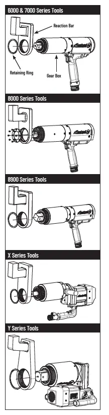
An optional feature (AEx4Bxxxxxxx models) on AcraDyne HT Series Nutrunners is a Slip Ring that allows the Gearbox to rotate 360 degrees in either direction related to the motor/handle assembly. This feature is useful in enabling the operator to position the reaction bar against a reactive point of sufficient structure prior to commencing tightening of the bolt. Operators MUST ensure that no hands, body parts, or other non-sufficiently structural elements are between the reaction bar and reactive point when positioning the reaction bar. Care MUST be taken to avoid tool start while positioning of the reaction bar is undertaken. Failure to practice safe reaction bar handling can result in SEVERE injury to person or damage to tool/application.
ENSURE THAT POWER TO THE CONTROLLER IS DISCONNECTED OR PROPER LOCK OUT/TAG OUT PROCEDURES ARE BEING FOLLOWED
- Orient the Reaction Bar so that the recess above the spline on the Reaction Bar is oriented towards the rear of the tool and any reaction foot is oriented away from the tool anvil
- Install the Reaction Bar onto the splines of the gearbox ensuring that the Reaction Bar is staying true to the splines.
- Install the Reaction Bar retaining ring/plate onto the end of the Gearbox securing the Reaction Bar in place on the Gearbox. FAILURE TO SECURE THE REACTION BAR PROPERLY CAN RESULT IN SEVERE INJURY TO THE OPERATOR AND/OR DAMAGE TO THE TOOL/APPLICATION
- Restore power/disengage Lock Out/Tag Out and prepare for use
THE TOOL HANDLE MUST NOT BE LOCATED AGAINST AN OBJECT OR RESTRICTION DURING OPERATION OF THE TOOL TO AVOID CREATION OF A PINCH POINT. AN OEM SOURCED OR APPROVED REACTION BAR OR PROPER REACTION ABSORPTION DEVICE MUST BE IN USE AND IN GOOD CONDITION ANY TIME THE TOOL IS OPERATED. PROPER TORQUE REACTION MANAGEMENT PRACTICES MUST BE OBSERVED AT ALL TIMES. FAILURE TO UNDERSTAND AND EMPLOY SAFE OPERATING TECHNIQUES CAN RESULT IN TOOL DAMAGE, APPLICATION DAMAGE, SEVERE PERSONAL INJURY, OR DEATH
When ready to begin tightening:
- Swivel the reaction bar (Slip Ring Equipped Models only) into position minimizing or ideally eliminating any gap between the Reaction Bar and the Reaction Surface of the application. On Fixed Gearcase models, ensure that reaction absorption device is configured properly.
- Complete the tightening event.
Reaction Bar Safety
AcraDyne® HT Nutrunning Systems deliver high amounts of torque to an application in a continuous drive manner. As is the nature with all tool systems that function in this manner, high amounts of torque reaction will occur. AcraDyne® HT systems work with Reaction Bars that engage the tool with a secure spline and when used correctly counteract the natural torque reaction in use by pressing against a part detail or adjacent nut/bolt.
- It is essential that these forces are understood completely by the operator and that the Reaction Bars have been chosen with the application’s specific geometry in mind.
- AcraDyne® offers a range of Reaction Bars from stock and will design specific Reaction Bars to suit specific applications upon request.
- It is the user’s responsibility to ensure that the correct Reaction Bar or Tool Holding Fixture is in place PRIOR to use of the AcraDyne® HT Series Nutrunner.
Reaction Bar Guidelines
CAUTION IS REQUIRED. FAILURE TO EXERCISE CAUTION AND CORRECT OPERATING TECHNIQUE CAN RESULT IN SERIOUS PERSONAL INJURY, LOSS OF LIMB OR DEATH.
The guidelines offered below are only guidelines. Should there be any doubt as to the integrity of a proposed reaction strategy, it is strongly advised to consult with an AcraDyne® authorized representative prior to executing strategy.
Reaction force is equal to the point being applied. The magnitude of the reaction force is dependent upon the perpendicular distance between the point of reaction and the centerline of the gearbox. In other words, the greater the distance the lower force experienced. For this reason, the point of reaction should be kept as far away from the centerline of the tool gearbox as possible.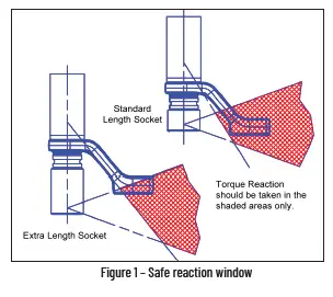
Sockets
CAUTION IS REQUIRED. FAILURE TO EXERCISE CAUTION AND CORRECT OPERATING TECHNIQUE CAN RESULT IN SERIOUS PERSONAL INJURY, LOSS OF LIMB OR DEATH.
Only Impact Grade, Industrial Sockets should be used with AcraDyne® HT Series Nutrunners. Mechanic-grade chrome sockets are not to be used as they do not have sufficient structural strength required to deliver the higher torque loads that an AcraDyne® HT Series Nutrunner is capable of delivering. In addition, the use of Socket Extensions of any length are strongly discouraged as they also will experience failure to an extent where tool damage or operator injury may occur.
Pinch Point
CAUTION IS REQUIRED. FAILURE TO EXERCISE CAUTION AND CORRECT OPERATING TECHNIQUE CAN RESULT IN SERIOUS PERSONAL INJURY, LOSS OF LIMB OR DEATH.
- The nature of a Reaction Bar in any continuous drive tool is to press against an object to counteract Torque Reaction as the tool is delivering Torque.
- The operator must take great care to keep body parts or foreign matter clear of the area between the Reaction Bar and the surface it is reacting against.
ANY BODY PART OR FOREIGN MATTER RESIDING IN A SPACE BETWEEN THE REACTION BAR AND THE SURFACE IT WILL REACT AGAINST WILL ENCOUNTER SIGNIFICANT FORCES THAT CAN CAUSE INJURY, LOSS OF LIMB OR DEATH.
Accessories
Custom accessories are available for your application; contact an AIMCO Customer Service Associate for details, 1-503-254-6600, or toll free 1-800-852-1368.
| Model | Description |
| 26477 | Swivel Bail, 6000 Series |
| 26327 | Swivel Bail, 7000 Series |
| 25287 | Swivel Bail, 8000 Series |
| 26630 | Swivel Bail, 8000/9000 Series Tools |
| 26478 | Swivel D-Handle, 6000 Series |
| 26328 | Swivel D-Handle, 7000 Series |
| 25291 | Swivel D-Handle, 8000 Series |
| 26479 | Stationary Bail, 6000 series (26336 handle not included) |
| 26332 | Stationary Bail, 7000 series (26336 handle not included) |
| 25289 | Stationary Bail, 8000 series (26336 handle not included) |
| 26336 | Fixed Handle (for use with 26479, 26332, 25289) |
| 26337 | Rear Fixed Hoist Ring, 6000/7000/8000 Series Pistols |
| 28514 | Rear Folding Hoist Ring Kit for 8000 Series Pistols |
| 28549 | Sliding Spindle, 6000 Series |
| 27045 | Sliding Spindle, 7000 Series |
| 30300 | Sliding Spindle, 8000 Series |
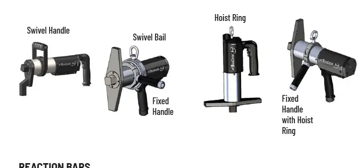
REACTION BARS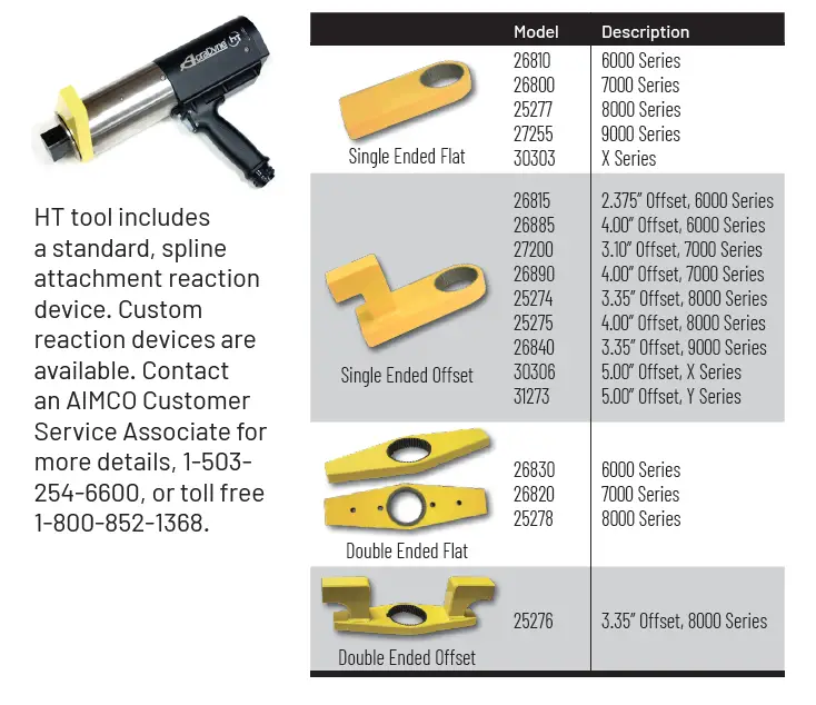
PROTECTIVE COVERS
Durable protective covers prevent marring and damage.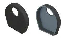
| Model | Description |
| BJ10078 | Protective Cover, 6000 Series |
| BJ10077 | Protective Cover, 7000 Series |
| BJ10076 | Protective Cover, 8000 Series |
HEAVY DUTY WATER-RESISTANT CASE FOR HT TOOLS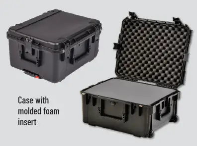
Made of ultra high-strength polypropylene copolymer resin, this water resistant utility case protects AcraDyne HT tools.
- Molded-in hinge, trigger-release latch system, and snap-down cushion grip handle
- Resistance to UV, solvents, corrosion, and impact damage
Model
Compatible Tools Description
CC-6000-F 6000 series Case with molded foam insert CC-6000-FIP 6000 series Case with foam in place CC-7000-F 7000 series Case with molded foam insert CC-7000-FIP 7000 series Case with foam in place CC-8000-F 8000 series Case with molded foam insert CC-8000-FIP 8000 series Case with foam in place
CABLE ASSEMBLIES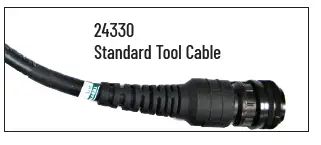
| 24330 | G3/G4 Tool Cable 3M | 3 | 9.8 |
| 25350 | G3/G4 Tool Cable 5M | 5 | 16.4 |
| 24320 | G3/G4 Tool Cable 10M | 10 | 32.8 |
| 24320 | Extension cable 10M | 10 | 32.8 |
| 25518 | Extension cable 20M | 20 | 65.6 |
The AcraDyne DC electric nutrunner tool system uses a single cable to carry all necessary conductors for superior ergonomics and durability.
- Flexible polyurethane cover for maximum durability, abrasion and transmission fluid resistant
- Quick disconnects at both ends facilitate tool changeover and troubleshooting
- The CAN data/signal is via RJ45 for products such as the KDM socket tray or computer
BREAKAWAY CABLE CONNECTOR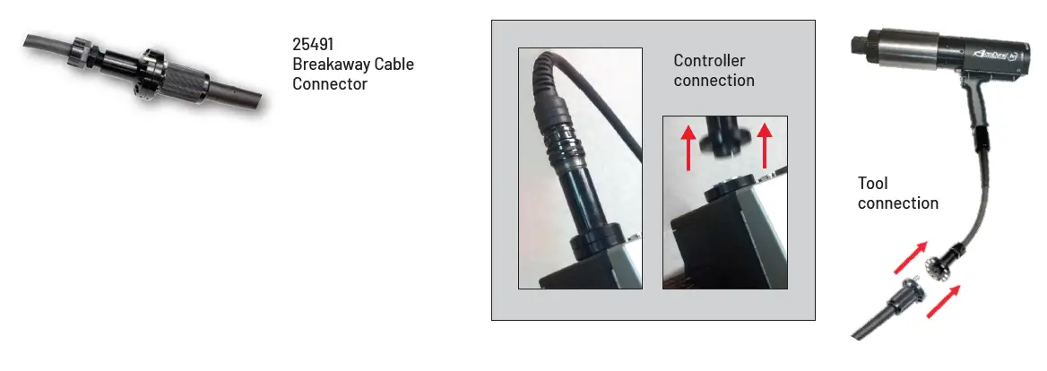
Innovative Quick Disconnect Device reduces cable damage from dropping tools or pulling cables when in use.
- Can be placed at the tool or at the controller
- Easily snaps into place
- Connects using magnetic force
- Adjust holding force by removing or adding magnets. Max holding force is 40 lbs / 18 kg
Recommended Maintenance
Any service or preventative maintenance must be done by a trained technician or AcraDyne Authorized Service Center.
- The tool gear train should be cleaned, inspected and re-greased every 25,000 tightening cycles.
- Parts should be inspected for wear and any worn parts should be replaced.
- In addition to this service, it is recommended that the tool should have its calibration checked at least annually or every 50,000 tightening cycles, whichever comes first.
AIMCO Limited Warranty
NEW TOOL AND ACCESSORY WARRANTY
Any new tool or accessory branded with the AIMCO, Uryu, AcraDyne or Eagle Group name, and purchased from AIMCO, or through one of its authorized distributors or agents, is warranted to the original buyer against defects in materials and workmanship for a period of one (1) year* from date of delivery. Under the terms of this warranty, AIMCO agrees, without charge, to repair or replace, at
its option and Ex-Works (EXW) its authorized service centers, any product or accessory warranted hereunder proving to AIMCO’s satisfaction to be defective as a result of defective workmanship or material. In order to qualify for this warranty, written notice to AIMCO must be given immediately upon discovery of such defect, at which time AIMCO will issue an authorization to return the tool. The defective item must be promptly returned to an authorized AIMCO service center with all freight charges prepaid.
REPAIRED TOOL WARRANTY
Once a tool is beyond the new product warranty period as detailed above, AIMCO will provide repair subject to the following warranty periods: pneumatic tools: 90 days*; electric tools and Acra-Feed: 90 days; battery tools: 30 days*; DC Electric tools: 90 days*
EXCLUSION FROM WARRANTY
This warranty is valid only on products purchased from AIMCO, or through its authorized distributors or agents. AIMCO shall have no obligation pursuant to the AIMCO Warranty with respect to any tools or accessories which in AIMCO’s sole judgment have been altered damaged, misused, abused, badly worn, lost or improperly maintained. This Warranty is null and void if the customer, or any other person other than an authorized representative of AIMCO, has made any attempt to service or modify the tool or accessory prior to its return to AIMCO under this Warranty.
The warranty provision with respect to each such product may be amended by AIMCO from time to time in its sole discretion. The liability of AIMCO hereunder shall be limited to replacing or repairing, at its option, any defective products which are returned freight pre-paid to AIMCO or, at AIMCO’s option, refunding the purchase price of such products.
AIMCO reserves the right to make periodic changes in construction or tool design at any time. AIMCO specifically reserves the right to make these changes without incurring any obligation or incorporating such changes or updates in tools or parts previously distributed.
THE AIMCO WARRANTY IS IN LIEU OF ALL OTHER WARRANTIES, EXPRESSED OR IMPLIED, AND AIMCO EXPRESSLY DISCLAIMS ANY WARRANTY OF MERCHANTABILITY OR FITNESS FOR A PARTICULAR PURPOSE. THIS WARRANTY SETS FORTH THE SOLE
AND EXCLUSIVE REMEDY IN CONTRACT, TORT, STRICT LIABILITY, OR OTHERWISE.
THIS WARRANTY IS THE ONLY WARRANTY MADE BY AIMCO WITH RESPECT TO THE GOODS DELIVERED HEREUNDER AND MAY BE MODIFIED OR AMENDED ONLY BY A WRITTEN INSTRUMENT SIGNED BY A DULY AUTHORIZED OFFICER OF AIMCO.
LIMITATION OF LIABILITY
AIMCO’S LIABILITY PURSUANT TO THE WARRANTY OF THE PRODUCTS COVERED HEREUNDER IS LIMITED TO REFUND OF THE PURCHASE PRICE. IN NO EVENT SHALL AIMCO BE LIABLE FOR COSTS OF PROCUREMENT OF SUBSTITUTE GOODS BY THE BUYER. IN NO EVENT SHALL AIMCO BE LIABLE FOR ANY SPECIAL, CONSEQUENTIAL, INCIDENTAL OR OTHER DAMAGES (INCLUDING WITHOUT LIMITATION, LOSS OF PROFIT) WHETHER OR NOT AIMCO HAS BEEN ADVISED OF THE POSSIBILITY OF SUCH LOSS, HOWEVER CAUSED, WHETHER FOR BREACH OR REPUDIATION OF CONTRACT, BREACH OF WARRANTY, NEGLIGENCE OR OTHERWISE. THIS EXCLUSION ALSO INCLUDES ANY LIABILITY WHICH MAY ARISE OUT OF THIRD PARTY CLAIMS AGAINST BUYER. THE ESSENTIAL PURPOSE OF THIS PROVISION IS TO LIMIT THE POTENTIAL LIABILITY OF AIMCO ARISING OUT OF THIS AGREEMENT AND/OR SALE.
NOTE: The AIMCO Warranty confers specific legal rights, however some states or jurisdictions may not allow certain exclusions or limitations within this warranty. *Note – All warranty periods addressed herein are determined using a standard shift, eight-hour work day.
AIMCO CORPORATE HEADQUARTERS 10000 SE Pine Street
Portland, Oregon 97216
Phone: (503) 254–6600
Toll Free: 1-800-852-1368
AIMCO CORPORATION DE MEXICO SA DE CV Ave. Cristobal Colon 14529
Chihuahua, Chihuahua. 31125
Mexico
Phone: (01-614) 380-1010
Fax: (01-614) 380-1019


