
Desoutter SH500-LR330-S90-A13S Angle Nutrunner User Manual
![]() WARNING
WARNING
TO REDUCE THE RISK OF INJURY, BEFORE USING OR SERVICING TOOL, READ AND UNDERSTAND THE FOLLOWING INFORMATION AS WELL AS SEPARATELY PROVIDED SAFETY INSTRUCTIONS (ITEM NUMBER: 2050502163)
Copyright
© Copyright 2022, Desoutter HP2 7SJ UK. All rights reserved. Any unauthorized use or copying of the contents or part thereof is prohibited. This applies in particular to trademarks, model denominations, part numbers and drawings. Use only authorized parts. Any damage or malfunction caused by the use of unauthorized parts is not covered by Warranty or Product Liability.
Statement of use
This product is designed for installing and removing threaded fasteners in wood, metal and plastic. No other use permitted. For professional use only. The use of spare parts/accessories other than those originally supplied by the manufacturer may result in a drop in performance and/or increased maintenance/noiselevel/vibrations, and as the result, the full cancellation of the manufacturer’s liability.
Installation
Air quality
- For optimum performance and maximum machine life we recommend use of compressed air with a dew point between +2°C and +10°C. Installation of a refrigeration-type air dryer is recommended.
- Use a separate air filter to remove solid particles larger than 30 microns and more than 90 % of water, installed as close as possible to the machine and prior to any other air preparation unit. Blow out the hose before connecting.
- The compressed air must contain a small quantity of oil. We strongly recommend that you install a oil-fog lubricator to be set normally at 3-4 drops(50mm3 )/m3 air consumption for long cycle running tools, or a single-point lubricator for short cycle running tools.
- Regarding lubrication free tools it is, at the customers option, no disadvantage if the compressed air contains a small quantity of oil as supplied from a lubricator. An exception is turbine tools that should be kept oil free. (For further information please see Air Line Accessories in our main catalogue.)
Compressed air connection
- The machine is designed for a working pressure of 6–7 bar = 600–700 kPa = 87–102 psi.
- Blow out the hose before connecting.
Handling
Tightening torque
For accurate operation and safety, the tightening torque of the nut runner must be set correctly in relation to the screw joint. Check the tightening torque given to the joint in question. The tightening torque is adjusted by altering the tension of the clutch spring. Turn the protection ring until the hole in the clutch housing is free. Then turn the out going spindle until you can see the keyhole in the adjustment washer. Turn the adjustment key clockwise to decrease and anticlockwise to increase the torque. After the adjustment, turn the protective ring back again.
WARNING
NEVER CONNECT A PART ASSEMBLED TOOL TO THE AIR SUPPLY. THE ROTOR BLADES IN THIS TOOL HAVE A PTFE CONTENT. THE NORMAL HEALTH AND SAFETY RECOMMENDATIONS CONCERNING PTFE MUST BE OBSERVED WHEN HANDLING THESE ROTOR BLADES.
- DO NOT SMOKE.
- MOTOR COMPONENTS MUST BE WASHED WITH CLEANING FLUID AND NOT BLOWN CLEAR WITH AN AIR LINE.
- THE SILENCER MUST BE REPLACED WHEN DIRTY, DO NOT CLEAN AND RE-USE.
- WASH HANDS BEFORE COMMENCING ANY OTHER ACTIVITY
Maintenance
- All torque figures ± 10%.
- When disposing of components, lubricants, etc …ensure that the relevant safety procedures are carried out.
- Overmold should be wiped clean with a general purpose, nonaggressive degreasant.
For maximum performance
It is important to lubricate regularly to get maximum performance and trouble-free operation. The motor should be lubricated with oil; i.e. drops of oil can be dropped either into the compressed air or directly into the air inlet. The trigger, planetary gears, needle bearings and ball bearings should be lubricated with grease during the regular overhaul of the machine. The angle gear and clutch must be lubricated using grease that contains molybdenum disulphide: Molykote BR2 Plus, for example, or an equivalent brand. Use lubricants of good quality. The oils and greases mentioned in the table are examples of lubricants which are recommended.
Rust protection and internal cleaning
Water in the compressed air, dust and wear particles cause rust and sticking of vanes, valves etc. An air filter should be installed close to the machine (see “Air quality”).
Reporting, RE – signal
Reporting (RE) machines supply an air signal that can be connected to a monitoring instrument that counts the number of approved tightening and detects premature shut-off and rehits and other irregularities.
Service instructions
Overhaul and preventive maintenance is recommended at regular intervals once per year or after maximum 250.000 tightening depending on which occurs sooner. More frequent overhaul may be needed, if used at high torque and long tightening times. If the machine not is working properly, it should immediately be taken away for inspection. The strainer at the air inlet and the exhaust silencer should be cleaned frequently or replaced in order to prevent clogging, which decreases the capacity. At the overhauls, all parts should be cleaned accurately and defective or worn parts (i.e. O-rings, vanes) should be replaced.
Disassembling/assembling
It is important that the machines threaded connections are tightened properly; i.e. in accordance with the specifications on the exploded views.
Lubricate o-rings and threaded connections with grease before assembling.
Cleaning
Clean all parts thoroughly in white spirit or similar cleaning agent. To prevent clogging and decreased power, it could be necessary to clean the strainer (if used) and the exhaust filter between the overhauls.
Inspection
After the cleaning, inspect all parts. Damaged and worn parts should be replaced.
Lubrication
Lubricate specially gears, valve and clutch with grease containing molybdenum disulphide (e.g. Molykote BR2 Plus). Please see exploded views and fig. under Service instructions.
Grease Guide
| BPCastrol Esso08MobilShellTexaco MolycoteLubricating Engineers | Energrease LS-EP2 Spheerol EP L2 Beacon EP2 Rembrandt EP2Mobilegrease XHP 222Alvania EP2 Multifak EP2 | BR2 PlusAlmagard3752 | Energol E46Arox EP46 Chopin 46Almo oil 525Tonna R32 Aries 32 |
Spare parts
Parts without ordering number are not delivered separately for technical reasons. The use of other than genuine Desoutter replacement parts may result in decreased tool performance and increased maintenance and may, at the company option, invalidate all warranties.
Technical data
| Rated speed and Torque range | |
| Rated speed (Rpm) | 330 |
| Torque range (Nm) | 25-50 |
| Noise and vibration emission | |
| Noise (according to EN ISO 15744) | dB(A) |
| Measured sound pressure level | Noisepressure-volume |
| Determined sound power levelSpread in method and production | 3 |
| Vibration (according to ISO 8662-7) | m/s2 |
| Measured vibration value | <2.5 |
| Spread in method and production | – |
Declaration of noise and vibration emission
All values are current as of the date of this publication. For the latest information please visit www.desouttertools.com.These declared values were obtained by laboratory type testing in accordance with the stated standards and are suitable for comparison with the declared values of other tools tested in accordance with the same standards. These declared values are not adequate for use in risk assessments and values measured in individual work places may be higher. The actual exposure values and risk of harm experienced by an individual user are unique and depend upon the way the user works, the workpiece and the workstation design, as well upon the exposure time and the physical condition of the user. We, Desoutter, cannot be held liable for the consequences of using the declared values, instead of values reflecting the actual exposure, in an individual risk assessment in a work place situation over which we have no control. This tool may cause hand-arm vibration syndrome if its use is not adequately managed. An EU guide to managing hand-arm vibration can be found at http://www.humanvibration.com/EU/VIBGUIDE.htm We recommend a programme of health surveillance to detect early symptoms which may relate to noise or vibration exposure, so that management procedures can be modified to help prevent future impairment.
EC DECLARATION OF CONFORMITY
We, Desoutter, 37 Mark road, Hemel Hempstead, Herts-UK, HP27BW, +44 (0) 1442 838999 declare under our sole responsibilitythat our product (with type and serial number, see front page) andin combination with our accessories, to which this declarationrelates is in conformity with the appropriate standard(s):
EN ISO 11148-6: 2010
and in accordance with the following directive(s):
2006/42/EC
Machinery DirectiveOrigin of the product: SwedenTechnical
file available from EU headquater.CP
38 rue Bobby Sands – BP 1027344818 Saint Herblain –
France+33 (0) 2 40 80 20 00Saint Herblain, 20/06/2012B.Blanchet,
General Manager Signature of issuer
Desoutter Warranty
- This Desoutter product is guaranteed against defective workmanship or materials, for a maximum period of 12 months following the date of purchase from Desoutter or its agents, provided that its usage is limited to single shift operation throughout that period. If the usage rate exceeds that of single shift operation, the warranty period shall be reduced on a pro rata basis.
- If, during the warranty period, the product appears to be defective in workmanship or materials, it should be returned to Desoutter or its agents, together with a short description of the alleged defect. Desoutter shall, at its sole discretion, arrange to repair or replace free of charge such items as are deemed faulty by reason of defective workmanship or materials.
- This warranty ceases to apply to products which have been abused, misused or modified, or which have been repaired using other than genuine Desoutter spare parts or by someone other than Desoutter or its authorized service agents.
- Should Desoutter incur any expense correcting a defect resulting from abuse, misuse, accidental damage or unauthorized modification, they will require that such expense shall be defrayed in full.
- Desoutter accepts no claim for labour or other expenditure made upon defective products.
- Any direct, incidental or consequential damages whatsoever arising from any defect are expressly excluded.
- This warranty is given in lieu of all other warranties, or conditions, expressed or implied, as to the quality, merchantability or fitness for any particular purpose.
- No one, whether an agent, servant or employee of Desoutter, is authorized to add to or modify the terms of this limited warranty in any way.
Angle head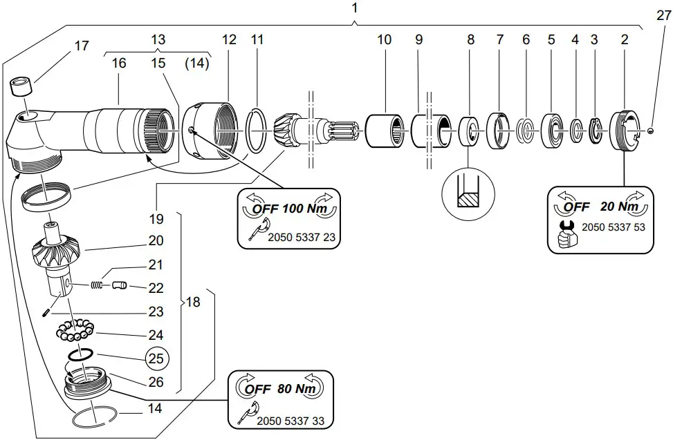
| Ref. No. | Ordering No. | Qty | Description | Remark / Included in Service kit |
| 1(2-26) | 2050 5032 13 | 1 | Angle head, compl. | 1/2” sq. |
| 2 | 2050 5100 13 | 1 | Nut | |
| 3 | 2050 5100 23 | 1 | Circlip | |
| 4 | 2050 5101 13 | 1 | Washer | |
| 5 | 2050 5100 33 | 1 | Ball bearing | 61901 |
| 6 | – | 1 | Shim | Note: The same shims which were originally assembled have to be used again after service. |
| 7 | 2050 5102 33 | 1 | Sleeve | |
| 8 | 2050 5102 43 | 1 | Spacer | |
| 9 | 2050 5101 53 | 1 | Spacer | |
| 10 | 2050 5101 63 | 1 | Needle bearing | F1720 |
| 11 | 2050 5100 63 | 1 | Ring | |
| 12 | 2050 5030 33 | 1 | Nut | |
| 13(14-16) | 2050 5139 63 | 1 | Angle head, kit | |
| 14 | 2050 5102 53 | 1 | Lock ring | |
| 15 | 2050 5102 63 | 1 | Protective ring | |
| 16 | – | 1 | Angle head | |
| 17 | – | 1 | Needle bearing | BK 1012 |
| 18(19-26) | 2050 5140 63 | 1 | Angle gear, compl. | |
| 19 | – | 1 | Pinion gear | |
| 20 | – | 1 | Bevel gear | |
| 21 | 2050 5101 83 | 1 | Spring | |
| 22 | 2050 5101 93 | 1 | Retainer pin | |
| 23 | 2050 5102 03 | 1 | Pin | FRP1.5×12 |
| 24 | 2050 5102 13 | 14 | Ball | 5 mm |
| 25 | – | 1 | O-ring | 17.1×1.6 / Service kit 2050 5140 53 |
| 26 | 2050 5102 23 | 1 | Nut | |
| 27 | 4595 43 | 1 | Ball | 4 mm |
Gear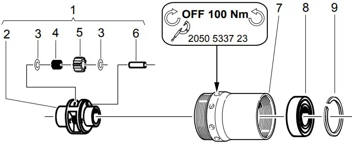
| Ref. No. | Ordering No. | Qty | Description | Remark! Included in Service kit |
| 1(2-6) | 2050 5105 03 | 1 | Planet shaft. compl. | =4.54 |
| 2 | 1 | Planet shaft | ||
| 3 | 2050 5105 23 | 6 | Washer | |
| 4 | 2050 5104 93 | 48 | Bearing needle | 1×6.8 |
| 5 | 2050 5105 33 | 3 | Gear wheel | z = 13 |
| 6 | 2050 5105 13 | 3 | Axle pin | |
| 7 | 2050 5030 53 | 1 | Casing | z = 39 |
| 8 | 2050 5104 33 | 1 | Ball bearing | 6002-Z |
| 9 | 4500 93 | 1 | Lock ring | I 32×1.2V |
Clutch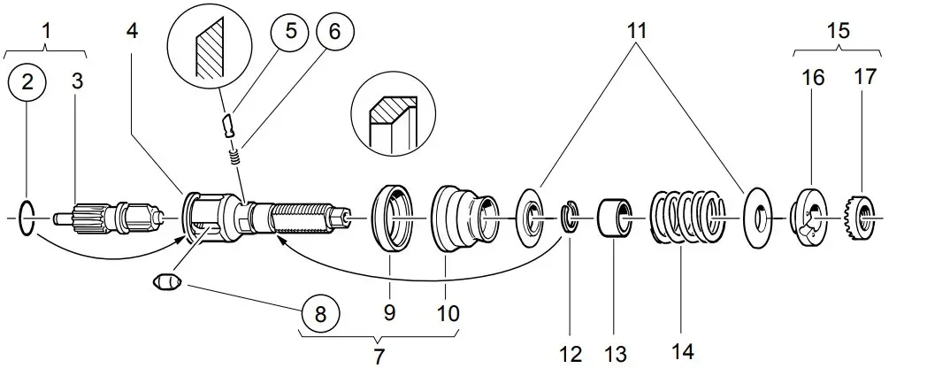
| Ref. No. | Ordering No. | Qty | Description | Remark / Included in Service kit |
| 1(2-3) | 2050 5139 53 | 1 | Driver, compl. | |
| 2 | – | 1 | O-ring | 13×1 / Service kit 2050 5140 53 |
| 3 | – | 1 | Driver | z = 11 |
| 4 | 2050 5107 13 | 1 | Clutch | |
| 5 | – | 1 | Stop pin | Service kit 2050 5140 53 |
| 6 | – | 1 | Spring | Service kit 2050 5140 53 |
| 7(8-10) | 2050 5139 43 | 1 | Coupling ring, compl. | |
| 8 | – | 3 | Roller | Service kit 2050 5140 53 |
| 9 | – | 1 | Ring | |
| 10 | – | 1 | Coupling ring | |
| 11 | 2050 5106 73 | 2 | Guide ring | |
| 12 | 2050 5107 03 | 1 | Circlip | H11x1 |
| 13 | 2050 5106 93 | 1 | Spacer | |
| 14 | 2050 5106 83 | 1 | Clutch spring | |
| 15(16-17) | 2050 5139 33 | 1 | Adjustment kit | |
| 16 | – | 1 | Adjustment washer | |
| 17 | – | 1 | Interlocking disc |
Clutch casing and gear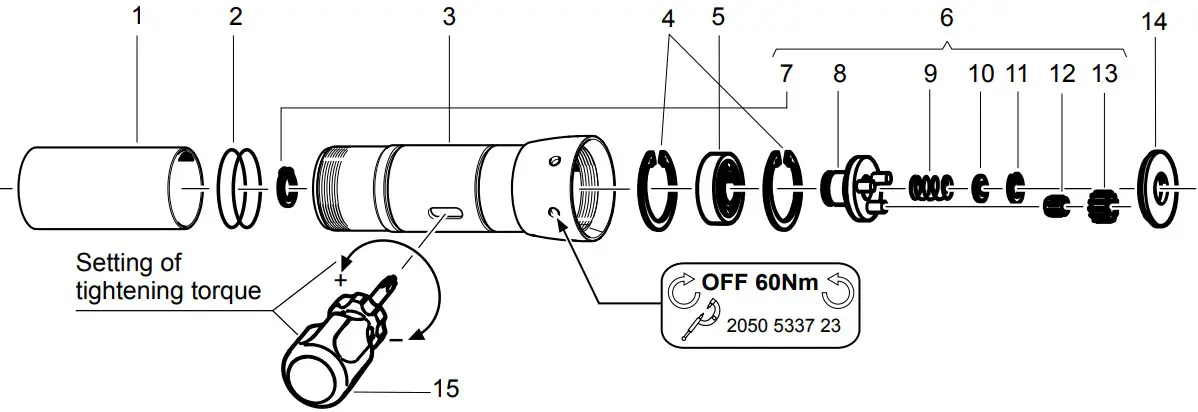
| Ref. No. | Ordering No. | Qty | Description | Remark / Included in Service kit |
| 1 | 2050 5162 53 | 1 | Cover | |
| 2 | 4507 23 | 2 | O-ring | 32,1×1,6 |
| 3 | 2050 5162 43 | 1 | Clutch housing | |
| 4 | 2050 5107 93 | 2 | Lock ring | 28×1.2V |
| 5 | 2050 5107 83 | 1 | Ball bearing | 6001-ZY |
| 6(7-13) | 2050 5601 03 | 1 | Planetary gear | |
| 7 | 2050 5100 23 | 1 | Circlip | SgA12 |
| 8 | – | 1 | Planet shaft | |
| 9 | 2050 5107 63 | 1 | Spring | |
| 10 | 2050 5105 23 | 1 | Washer | |
| 11 | 2050 5107 53 | 1 | Circlip | Sgh9 |
| 12 | 2050 5107 43 | 3 | Needle bearing | K4x7x7 |
| 13 | 2050 5107 33 | 3 | Gear wheel | z = 19 |
| 14 | 2050 5107 23 | 1 | Washer | |
| 15 | 2050 5078 53 | 1 | Adjustment key | Accessory included |
Motor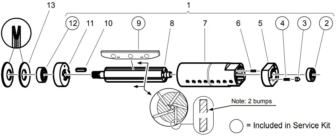
| Ref. No. | Ordering No. | Qty | Description | Remark / Included in Service kit |
| 1(2-12) | 2050 5108 63 | 1 | Motor, compl. | |
| 2 | – | 1 | Ball bearing | 625-2Z / Service kit 2050 5140 53 |
| 3 | – | 1 | Retainer pin | Service kit 2050 5140 53 |
| 4 | – | 1 | Spring | Service kit 2050 5140 53 |
| 5 | 2050 5108 73 | 1 | End plate | |
| 6 | 4498 03 | 1 | Pin | CP2x6 |
| 7 | 2050 5108 83 | 1 | Cylinder | |
| 8 | 2050 5108 93 | 1 | Rotor | z = 9 |
| 9 | 2050 5342 13 | 1 | Vane kit | 5 pcs |
| 10 | 4501 43 | 1 | Key | RK2x2x12 |
| 11 | 2050 5109 03 | 1 | End plate | |
| 12 | – | 1 | Ball bearing | 607-2Z / Service kit 2050 5140 53 |
| 13 | 2050 5109 13 | 2 | Cup spring | 31.5×12.2×1 |
Motor casing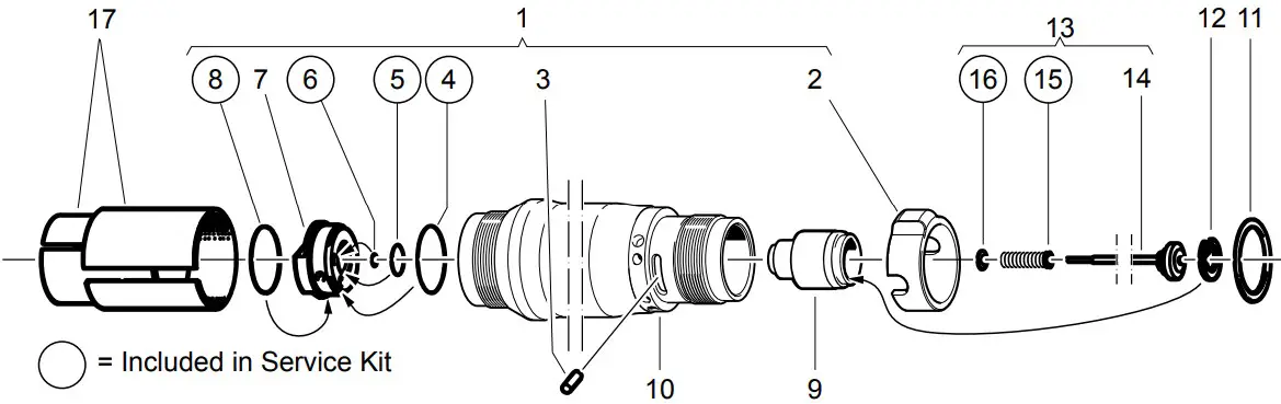
| Ref. No. | Ordering No. | Qty | Description | Remark / Included in Service kit |
| 1(2-8) | 2050 5139 73 | 1 | Reversing valve, compl. | |
| 2 | 2050 5031 43 | 1 | Reversing ring | |
| 3 | 2050 5109 53 | 1 | Pin | CP3x10 |
| 4 | – | 1 | O-ring | 23.5×1 / Service kit 2050 5140 53 |
| 5 | – | 1 | O-ring | 10.4×1 / Service kit 2050 5140 53 |
| 6 | – | 1 | O-ring | 2×1 / Service kit 2050 5140 53 |
| 7 | – | 1 | Reversing valve | |
| 8 | – | 1 | O-ring | 26×1.2 / Service kit 2050 5140 53 |
| 9 | 2050 5109 63 | 1 | Valve seat | |
| 10 | 2050 5031 13 | 1 | Motor casing | |
| 11 | 2050 5109 23 | 1 | Spacer | 26x30x0.3 |
| 12 | 2050 5109 33 | 1 | Circlip | SgH 16 |
| 13(14-16) | 2050 5139 83 | 1 | Valve, compl. | |
| 14 | – | 1 | Valve | |
| 15 | – | 1 | Spring | Service kit 2050 5140 53 |
| 16 | – | 1 | Washer | BRB2.2×4.5 / Service kit 2050 5140 53 |
| 17 | 2050 5109 83 | 2 | Silencer |
Back head and silencer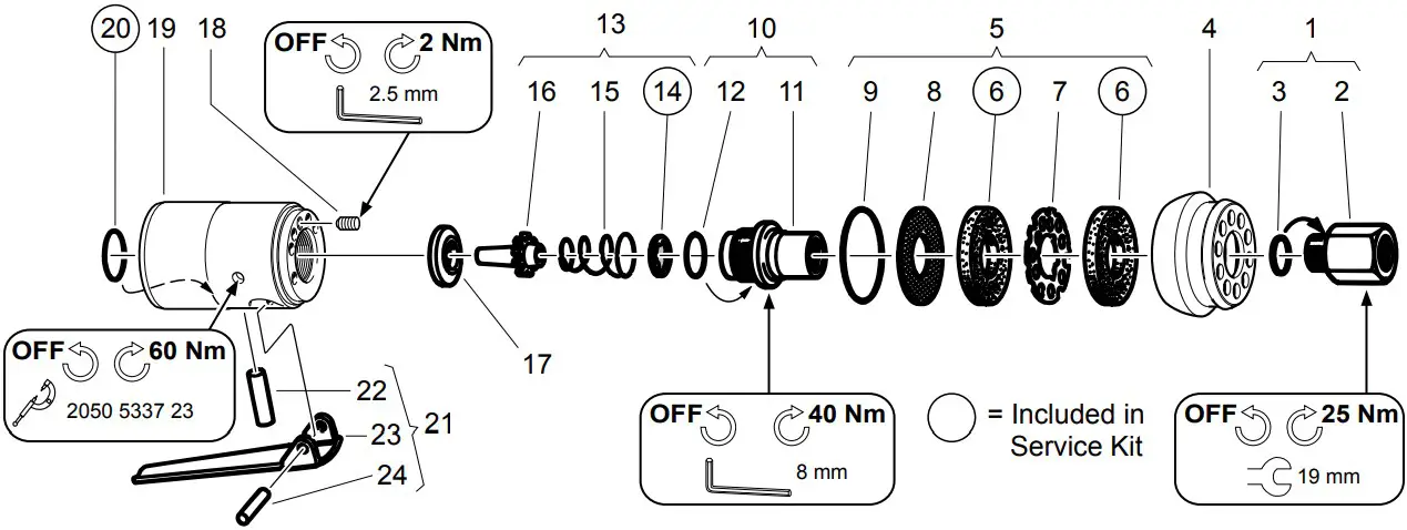
| Ref. No. | Ordering No. | Qty | Description | Remark / Included in Service kit |
| 1(2-3) | 2050 5139 93 | 1 | Adapter, compl. | With NPT-thread (for the US and Canada) 2050 5140 03 |
| 2 | – | 1 | Adapter | G 1/4″ |
| 3 | 2050 5109 93 | 1 | O-ring | 11.1x 1.6 |
| 4 | 2050 5031 73 | 1 | Distributor | |
| 5(6-9) | 2050 5140 13 | 1 | Silencer, compl. | |
| 6 | – | 2 | Filter | Service kit 2050 5140 53 |
| 7 | 2050 5110 13 | 1 | Washer | |
| 8 | 2050 5110 23 | 1 | Silencer | |
| 9 | 4507 23 | 1 | O-ring | 32.1x 1.6 |
| 10(11-12) | 2050 5140 23 | 1 | Adapter, compl. | |
| 11 | – | 1 | Adapter | |
| 12 | 2050 5110 33 | 1 | O-ring | 17.5x 1.3 |
| 13(14-16) | 2050 5140 33 | 1 | Valve, compl. | |
| 14 | – | 1 | Strainer | Service kit 2050 5140 53 |
| 15 | 2050 5110 43 | 1 | Spring | |
| 16 | – | 1 | Valve | |
| 17 | 2050 5110 53 | 1 | Ring | |
| 18 | 2050 5110 63 | 1 | Screw | M5x5 |
| 19 | 2050 5031 53 | 1 | Back head | |
| 20 | – | 1 | O-ring | 17.5×1.3 (Also included in Reversing valve 2050 5139 73) / Service kit 2050 5140 53 |
| 21(22-24) | 2050 5140 43 | 1 | Lever, compl. | |
| 22 | 2050 5110 83 | 1 | Pin | |
| 23 | – | 1 | Lever | |
| 24 | 2050 5110 93 | 1 | Pin | 2.5×22 |
Optional accessories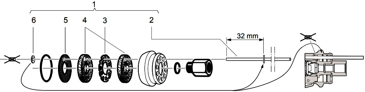
| Ref. No. | Ordering No. | Qty | Description Remark / Included in Service kit |
| 1(2-6) | 2050 5017 53 | 1 | Kit, RE-signal |
| 2 | 2050 5088 83 | 1 | Hose |
| 3 | 2050 5110 13 | 1 | Washer |
| 4 | 2050 5111 03 | 2 | Filter |
| 5 | 2050 5111 13 | 1 | Silencer |
| 6 | 2050 5111 23 | 1 | Lock ring |
Exhaust hose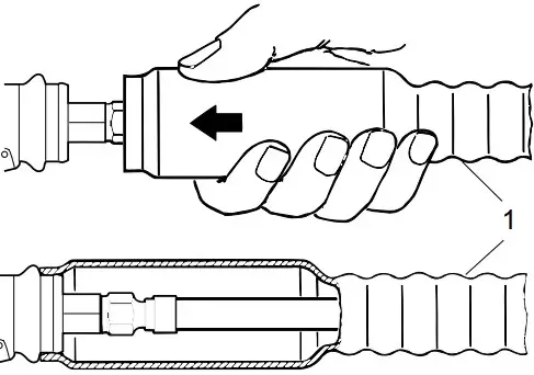
| Ref. No. | Ordering No. | Qty | Description Remark / Included in Service kit |
| 1 | 4598 13 | 1 | Exhaust hose |
Suspension yoke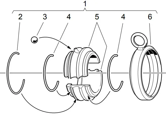
| Ref. No. | Ordering No. | Qty | Description | Remark / Included in Service kit |
| 1(2-6) | 2050 5111 53 | 1 | Suspension yoke, compl. | Swivel |
| 2 | 2050 5111 63 | 1 | Spring | |
| 3 | 2050 5111 73 | 22 | Ball | |
| 4 | 2050 5111 83 | 2 | Spring | |
| 5 | – | 1 | Inner ring | |
| 6 | – | 1 | Outer ring |
Suspension yoke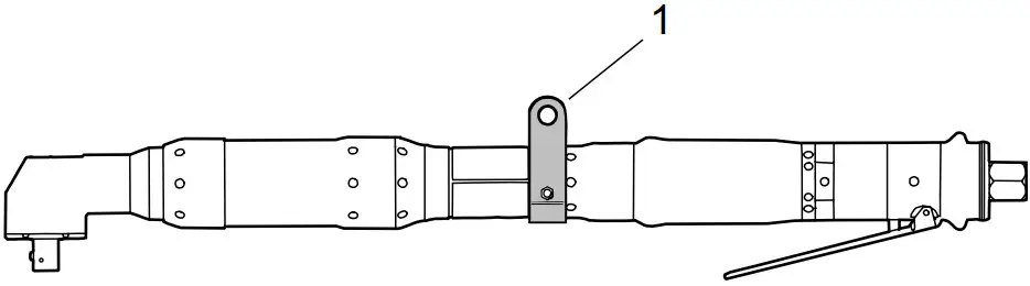
| Ref. No. | Ordering No. | Qty | Description | Remark / Included in Service kit |
| 1 | 2050 5111 33 | 1 | Suspension yoke, compl. |
Protective cover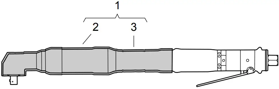
| Ref. No. | Ordering No. | Qty | Description | Remark / Included in Service kit |
| 1(2-3) | 2050 5018 23 | 1 | Proctective cover, compl. | |
| 2 | 2050 5111 43 | 4 | Strap | |
| 3 | – | 1 | Protective cover |
Quick change retainer pin
| Ref. No. | Ordering No. | Qty | Description | Remark / Included in Service kit |
| 1 | 2050 5112 93 | 1 | Quick change retainer pin |
Service Kits
Service Kit 2050 5140 53
Ordering No. 2050 5140 53
| Ordering No. | Qty | Description | Remark / Included in Service kit |
| – | 1 | Washer | 2,2×4,5 FZ |
| – | 1 | Ball bearing | 607-2Z |
| – | 1 | Ball bearing | 625-2Z |
| – | 1 | O-ring | 2×1 |
| – | 1 | O-ring | 13×1,2 |
| – | 1 | O-ring | 21,6×1,6 |
| – | 2 | O-ring | 17,5×1,3 |
| – | 1 | O-ring | 17,1×1,6 |
| – | 1 | O-ring | 27,1×1,6 |
| – | 1 | O-ring | 26×1,2 |
| – | 1 | O-ring | 10,4×1 |
| – | 1 | O-ring | 23,5×1 |
| – | 2 | O-ring | 32,1×1,6 |
| – | 1 | Spring | |
| – | 1 | Strainer | |
| – | 1 | Spring | |
| – | 3 | Roller | |
| – | 1 | Catch | |
| – | 1 | O-ring | 13×1 |
| – | 5 | Vane | |
| – | 2 | Filter | |
| – | 1 | Spring | |
– | 1 | Tap |
Kit for a variety of products. Some parts might remain unused.
Service instructions
Tightening of threaded connections
The tightening torques indicated in the exploded views list are established to achieve the correct clamping force and preventing the parts from coming loose. At service these parts must be able to open up without being destroyed. In special circumstances (depending on application and usage) the parts may however come loose after some time of operation. In such cases the torque could be increased 10-20% and if necessary some type of low or medium threadlocking fluid could also be applied.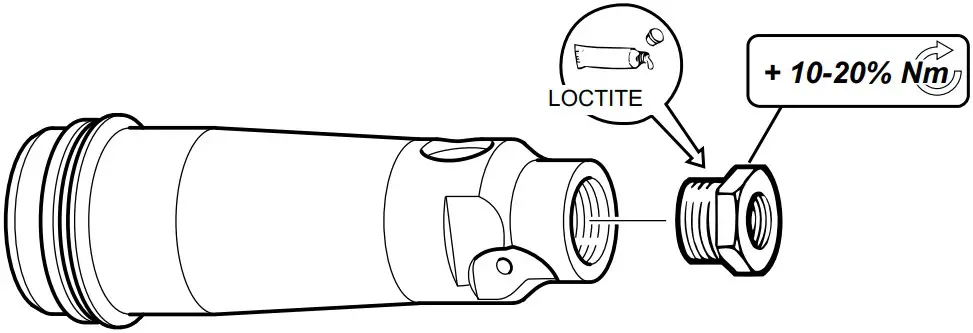
Diagram, RE – signal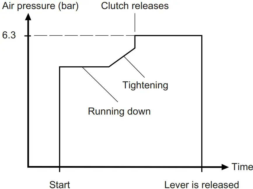
With the RE-signal Kit an air pressure signal will be supplied, which can be connected to a control unit to count the number of tightening and to detect premature and rehits.
Check of valve position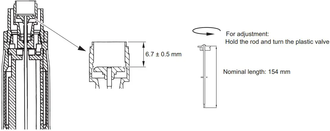
Instructions for vane motor
Dismantling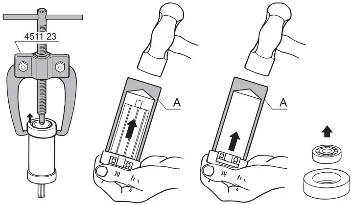
Dismantling tool Mandrel A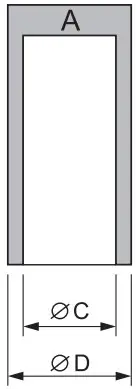
| Ordering No. 0 D | 0 C | For tool | |
| 4509 73 4509 63 | 2630 | 20.525.5 | SH70/SH150/SH200/SH280 SH420/SHSO0/SH700/SH850SH1200/SH2000 |
Inspection and lubrication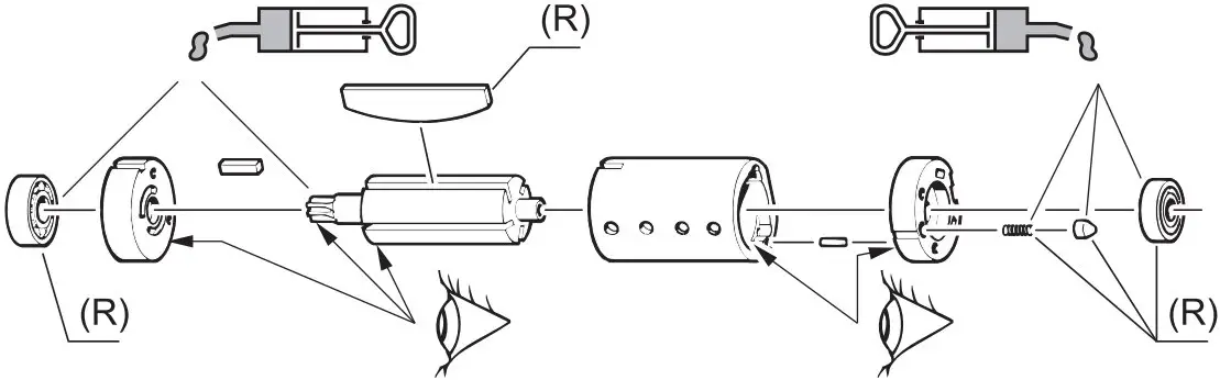
Assembly
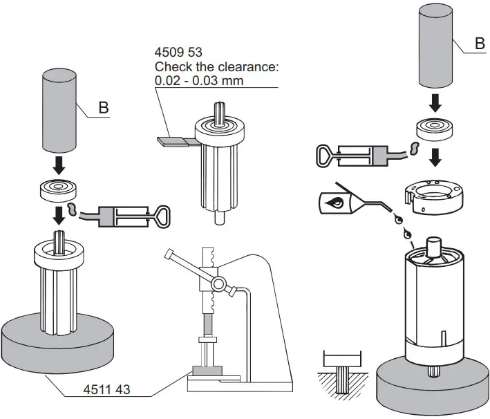
Assembly tool Mandrel B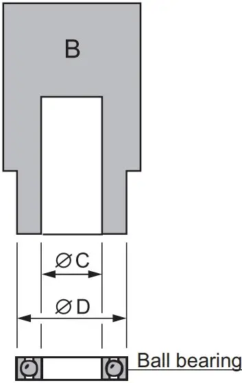
| 11,1.411IKj | For tool: | Rear bearing | |||
| Ordering No. | 0 D | 0 C | Front bearing | ||
| 2050 5145 | 33 | 21.5 | 12.5 | SH70/SH150 SH200/SH280 SH420/SHSO0 SH700/SH850 | SH1200/SH2000 |
| 4511 63 | 15.5 | 5.2 | SH70/SH150 SH200/SH280 SH420/SHSO0 SH700/SH850 | ||
| 4595 93 | 25.5 | 10.5 | SH1200/SH2000 | ||
Static measurement / Dynamic measurement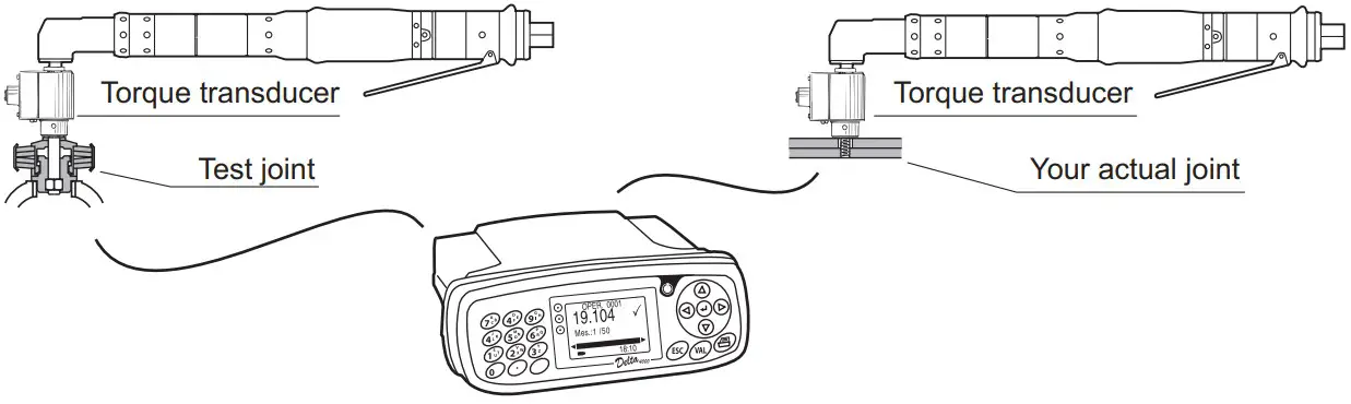
| Part Number | Model | Transducer | Thread | |
| 615 910 927 0 | ACS5.01 | ST4001 | M5 | |
| 615 910 928 0 | ACS6.05 | ST4005 | M6 | |
| 615 910 929 0 | ACS6.10 | ST4010 | M6 | |
| 615 910 930 0 | ACS8.05 | ST4005 | M8 | |
| 615 910 931 0 | ACS8.10 | ST4010 | M8 | |
| 615 910 932 0 | ACS10.10 | ST4010 | M10 | |
| 615 910 933 0 | ACS10.50 | ST4050 | M10 | |
| 615 910 934 0 | ACS10.50 | ST4050 | M12 | |
| 615 910 935 0 | ACS10.50 | ST4050 | M16 | |
| Stationary Transducer | ||||
| Part Number | Model | Torque Range Nm | Torque Range ft.lb | |
| 615 165 141 0 | ST4001 | 1-15 | 0,7-11,1 | |
| 615 165 142 0 | ST4005 | 5-70 | 3,7-51,6 | |
| 615 165 143 0 | ST4010 | 10-150 | 7,4-110,5 | |
| 615 165 144 0 | ST4050 | 50-700 | 36,8-516 | |
In Static as well as Dynamic measurement, it is advised to double check by the use of a Dial Indicating Torque Wrench* (direct reading) or a Torsion Static Torque Wrench** (connected to the Delta 4000 or Sigma 2001).
For further information regarding our complete measurement range, see our general catalogue.
Torque Transducer
| Part Number | Model | Torque Range Nm | Torque Range ft.lb |
| 615 165 211 0 | DRT 4 H 20 | 1,5-20 | 1,11-14,7 |
| 615 165 212 0 | DRT 4 Sq 20 | 1,5-20 | 1,11-14,7 |
| 615 165 213 0 | DRT 4 Sq 25 | 1,8-25 | 1,33-18,4 |
| 615 165 214 0 | DRT 4 Sq 75 | 5,0-75 | 3,69-55,3 |
| 615 165 215 0 | DRT 4 Sq 180 | 12,0-180 | 8,85-132 |
| 615 165 216 0 | DRT 4 Sq 500 | 35,0-500 | 25,8-368 |
Dial Indicating Torque Wrenches*
| Part Number | Model | Range metric | ial |
| 81972 | TW-13 | 0,5-13,5 Nm | 4-120 lbf in |
| 81982 | TW-27 | 1-27 Nm | 1-20 lbf ft |
| 81992 | TW-80 | 6-80 Nm | 5-60 lbf ft |
| 82002 | TW-160 | 10-160 Nm | 7,4-120 lbf ft |
| Torsion Static Torque Wrenches** | |||
| Part Number | Model | Torque Range metric | Torque Range imperial |
| 615 165 146 0 | CD4001 | 1-15 Nm | 0,7-11 lbf in |
| 615 165 147 0 | CD4005 | 5-70 Nm | 3,7-51,6 lbf ft |
| 615 165 148 0 | CD4010 | 10-150 Nm | 7,4-110,5 lbf ft |
| 615 165 149 0 | CD4050 | 50-700 Nm | 36,8-516 lbf ft |
| 615 165 150 0 | CD4101 | 100-1500 Nm | 73,7-1105 lbf ft |


