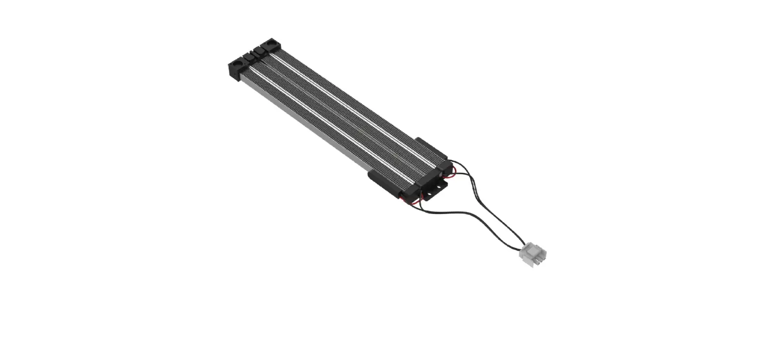
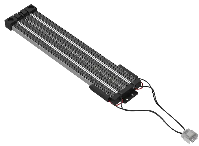
FURRION C-FACR15SA-A04 Heat Strip
This manual will guide you through proper installation of the Furrion heat strip. If retrofitting, please refer to your existing user manual to uninstall the rooftop and trim kit from the RV, and then follow the instructions to install the heat strip.
DANGER
Electric Shock Hazard
- Disconnect power or shut off the air conditioner circuit breaker before installation.
- Failure to do so can result in electric shock.
WHAT’S IN THE BOX
- Heat Strip
- ST4 x 9mm Screw with Washer
- Electric Control Box
- User Manual
- Warranty Manual
INSTALL/REPLACING THE HEAT STRIP
IMPORTANT: Installation of the heat strip must be carried out by a professional/certificated technician only.
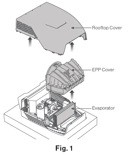
Disassemble the Top Unit
Remove the rooftop cover by removing the fixing screws. Pull to remove the evaporator EPP cover to access the evaporator. (Fig. 1)
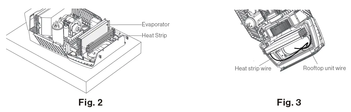
Heat Strip Installation
Use 4 ST4*9mm screws and washers (provided) to attach the heat strip on the evaporator. (Fig. 2) Fix the harnesses together with nylon cable ties (not provided). Then pass the 2 harnesses down through the air intake vent to the RV. (Fig. 3)
NOTE: Retain wire harnesses away from the electric heater element and evaporator to prevent being damaged.
WIRE CONNECTION
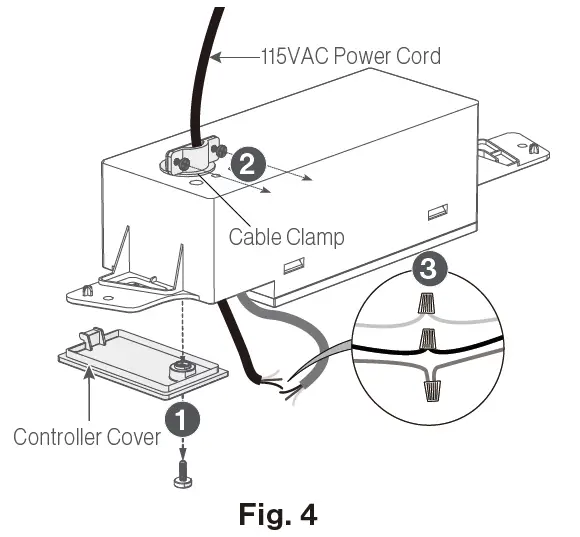
- Remove the controller cover on the control box by unscrewing its screw.
- Loosen the 2 screws of the power cord clamp on the back of the control box.
- Pass the 115VAC power cord through the cable clamp hole and make wire connections following the below color codes (Fig. 4):

- Black – Hot
- White – Neutral
- Green/Yellow – Ground
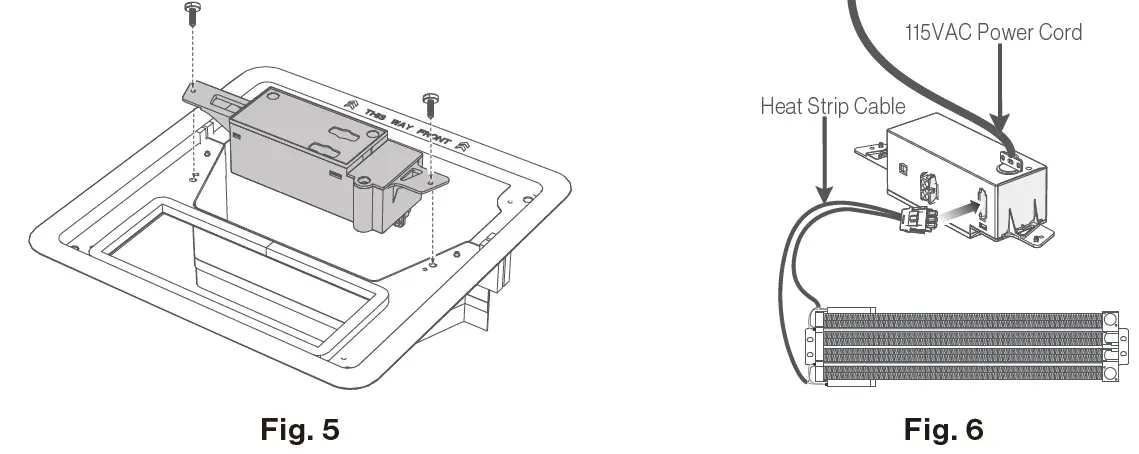
- Plug the 3-pin connector of the rooftop into the 3-pin terminal interface on the control box. (Fig. 5)

- When the heat strip is connected properly, secure the electrical box trim kit body.
SET UP
Set up the DIP Switches
Set up the control box dip switches as indicated in the illustration and table below.

| Zone Selection | DIP 1 : DIP 2 | DIP 1 | DIP 2 | Selected |
| OFF | OFF | ZONE1 | ||
| OFF | ON | ZONE2 | ||
| ON | OFF | ZONE3 | ||
| ON | ON | ZONE4 | ||
| Heat Pump (selected models) | DIP 3 | Reserved | ||
| Furnace | DIP 4 | OFF | Furnace Off | |
| ON | Furnace On | |||
| Electric Heat (selected models) | DIP 5 | OFF | Heat Strip Off | |
| ON | Heat Strip On | |||
| Analog / Digital | DIP 6 | OFF | Digital | |
| ON | Analog | |||
Switch DIP 5 to ON position to activate the heat strip function. Refer to your Wall Thermostat for operation of your heat strip.
SPECIFICATION
| Heating Capacity | 1,500W |
| Applicable Ambient Temperature in cooling | -7°C~30°C (19°F~86°F) |
| Volts/Hertz | 115V~/60Hz/1Ph |
| Power Watts | 1,500W |
| Amps | 14.6A |
| Power Cord Gauge | AWG14 (1.6 mm2) |
| Dimensions (W x H x D) | 1713/16″ x 15/16″ x 37/8″ (452mm x 23.5mm x 98mm) |
| Weight (lbs/kg) | 1.63/0.74 |
| Safety Standard | CSA/UL 60335-1, Second Edition & CSA/UL 60335-2-40, Second Edition |


