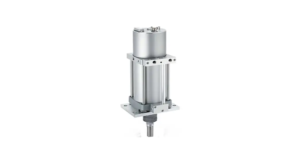
![]() PRODUCT NAME Air Servo Cylinder
PRODUCT NAME Air Servo Cylinder
For HART Communication
MODEL/ Series/ Product Number
IN-777-TF-F-HL
Instruction Manual
Safety Instructions
These safety instructions are intended to prevent hazardous situations and/or equipment damage.
These instructions indicate the level of potential hazard with the labels of “Caution,” “Warning” or “Danger.” They are all important notes for safety and must be followed in addition to International Standards (ISO/IEC)*1) , and other safety regulations.
*1) ISO 4414: Pneumatic fluid power — General rules relating to systems.
ISO 4413: Hydraulic fluid power — General rules relating to systems.
IEC 60204-1: Safety of machinery — Electrical equipment of machines .(Part 1: General requirements)
ISO 10218: Manipulating industrial robots -Safety. etc.
| Caution | Caution indicates a hazard with a low level of risk which, if not avoided, could result in minor or moderate injury. | |
| Warning | Warning indicates a hazard with a medium level of risk which, if not avoided, could result in death or serious injury. | |
| Danger | Danger indicates a hazard with a high level of risk which, if not avoided, will result in death or serious injury. |
Warning
- The compatibility of the product is the responsibility of the person who designs the equipment or decides its specifications.
Since the product specified here is used under various operating conditions, its compatibility with specific equipment must be decided by the person who designs the equipment or decides its specifications based on necessary analysis and test results.
The expected performance and safety assurance of the equipment will be the responsibility of the person who has determined its compatibility with the product.
This person should also continuously review all specifications of the product referring to its latest catalog information, with a view to giving due consideration to any possibility of equipment failure when configuring the equipment. - Only personnel with appropriate training should operate machinery and equipment.
The product specified here may become unsafe if handled incorrectly.
The assembly, operation and maintenance of machines or equipment including our products must be performed by an operator who is appropriately trained and experienced. - Do not service or attempt to remove product and machinery/equipment until safety is confirmed.
- The inspection and maintenance of machinery/equipment should only be performed after measures to prevent falling or runaway of the driven objects have been confirmed.
- When the product is to be removed, confirm that the safety measures as mentioned above are implemented and the power from any appropriate source is cut, and read and understand the specific product precautions of all relevant products carefully.
- Before machinery/equipment is restarted, take measures to prevent unexpected operation and malfunction.
- Contact SMC beforehand and take special consideration of safety measures if the product is to be used in any of the following conditions.
- Conditions and environments outside of the given specifications, or use outdoors or in a place exposed to direct sunlight.
- Installation on equipment in conjunction with atomic energy, railways, air navigation, space, shipping, vehicles, military, medical treatment, combustion and recreation, or equipment in contact with food and beverages, emergency stop circuits, clutch and brake circuits in press applications, safety equipment or other applications unsuitable for the standard specifications described in the product catalog.
- An application which could have negative effects on people, property, or animals requiring special safety analysis.
- Use in an interlock circuit, which requires the provision of double interlock for possible failure by using a mechanical protective function, and periodical checks to confirm proper operation.
![]() Caution
Caution
The product is provided for use in manufacturing industries.
The product herein described is basically provided for peaceful use in manufacturing industries.
If considering using the product in other industries, consult SMC beforehand and exchange specifications or a contract if necessary.
If anything is unclear, contact your nearest sales branch.
Limited warranty and Disclaimer/Compliance Requirements
The product used is subject to the following “Limited warranty and Disclaimer” and “Compliance Requirements”.
Read and accept them before using the product.
Limited warranty and Disclaimer
- The warranty period of the product is 1 year in service or 1.5 years after the product is delivered,whichever is first.2) Also, the product may have specified durability, running distance or replacement parts. Please consult your nearest sales branch.
- For any failure or damage reported within the warranty period which is clearly our responsibility, a replacement product or necessary parts will be provided. This limited warranty applies only to our product independently, and not to any other damage incurred due to the failure of the product.
- Prior to using SMC products, please read and understand the warranty terms and disclaimers noted in the specified catalog for the particular products. 2) Vacuum pads are excluded from this 1 year warranty. A vacuum pad is a consumable part, so it is warranted for a year after it is delivered. Also, even within the warranty period, the wear of a product due to the use of the vacuum pad or failure due to the deterioration of rubber material are not covered by the limited warranty.
Compliance Requirements
- The use of SMC products with production equipment for the manufacture of weapons of mass destruction (WMD) or any other weapon is strictly prohibited.
- The exports of SMC products or technology from one country to another are governed by the relevant security laws and regulation of the countries involved in the transaction. Prior to the shipment of a SMC product to another country, assure that all local rules governing that export are known and followed.
![]() Caution
Caution
SMC products are not intended for use as instruments for legal metrology.
Measurement instruments that SMC manufactures or sells have not been qualified by type approval tests relevant to the metrology (measurement) laws of each country.
Therefore, SMC products cannot be used for business or certification ordained by the metrology (measurement) laws of each country.
Introduction
This operation manual applies to the Air Servo Cylinder HART communication specifications (Product No.: IN-777-TF-F-HL)
IN-777 Air Servo Cylinder provides HART protocol communication as an option. Calibration, operation setting, and data confirmation become available by using 475 field communicator. Refer the manual of EMERSON for the operation.
This operation manual specifies HART communication functions only. Operation manual of “Air Servo Cylinder (No.K35-OMW0030)” shall be referred for basic operation of IN-777 Air Servo Cylinder.
Specifications
Other than HART communication, specifications are the same as basic type. Refer “4.Specification” of operation manual of “Air Servo Cylinder (No.K35-OMW0030)” for specifications.
Function of HART Communication
Table 1 shows main functions of HART communication.
Table 1
| Description | Details |
| 1.Checking and changing of the equipment information | Checking and changing of the Air Servo Cylinder information |
| 2.Checking and changing of the HART communication setting | |
| 3.Setting and checking of the parameter | Setting of the operation mode |
| Setting of the operating direction | |
| Setting of the valve position when OmA is input (Fully closed / fully opened / current position retained) | |
| Setting of the cylinder bore size | |
| Setting of the maximum cylinder speed | |
| 4.Calibration | Setting of the set point (Position where dart valve closed) |
| 5.Setting and checking of the operation mode | Command of the Emergency stop (E-stop) and stop-release |
| Switching to 4-20mA mode, JOG mode, or Parameter mode | |
| 6.JOG operation | Start / stop command to the JOG operation |
| 7.Checking of the operating conditions | Current position of the cylinder |
| Target position of the cylinder | |
| Error and alarm status | |
| Travel distance | |
| Rod friction count | |
| Movement area | |
Parameter Comparison
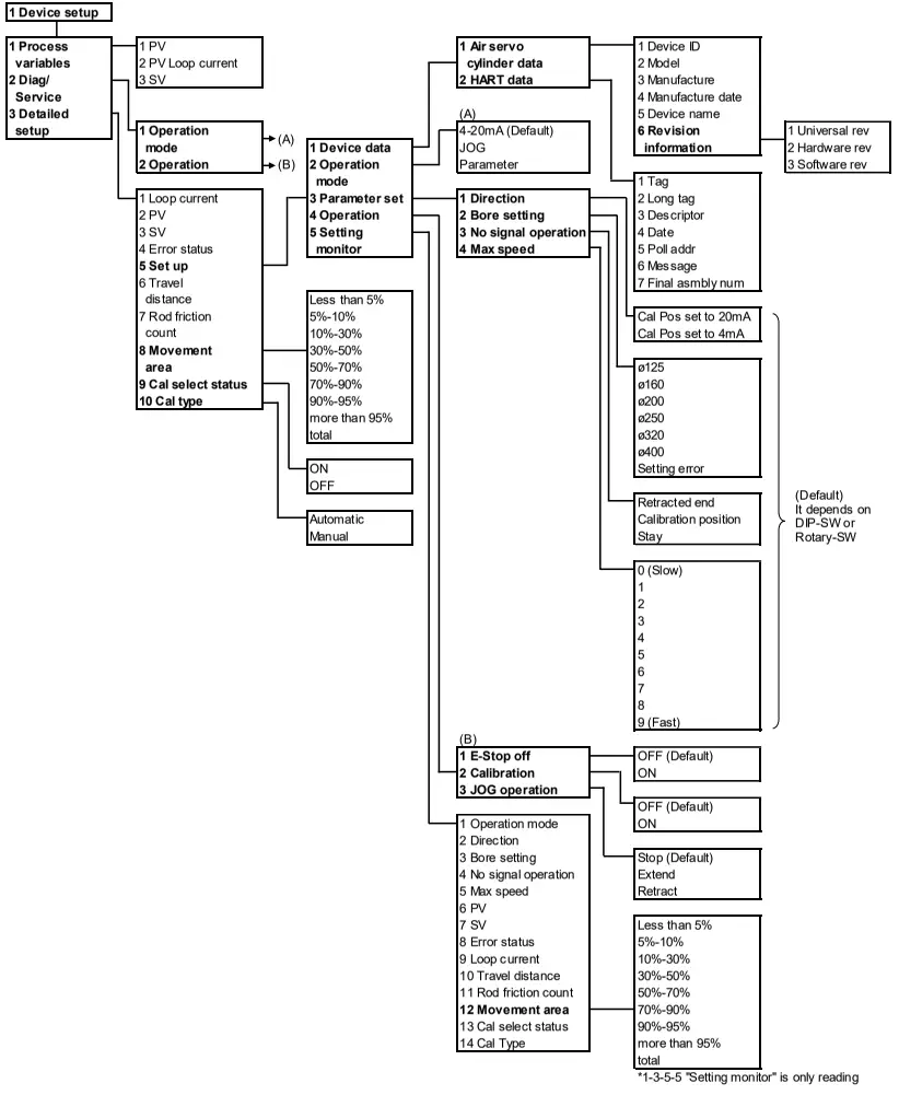
In HART communication parameter setting items, there are items which function is the same as button operation of the main unit, but different description. Table 2 shows the comparison of expression of Operation manual “Air Servo Cylinder (No.K35-OMW0030)” and the expression of 475 field communicator. Refer “4. Menu Tree”.
| Operation manual (No.K35-OMW0030) | 475 Field Communicator | Menu tree No. | |
| Expression | setting | ||
| Target position | PV | - | 1-3-2 |
| Feedback position | SV | - | 1-3-3 |
| Error status | Error status | - | 1-3-4 |
| Operation mode | Operation mode | 4-20mA | 1-3-5-2 |
| JOG | |||
| Parameter | |||
| Piston rod movement direction | Direction | Cal Pos set to 20mA | 1-3-5-3-1 |
| Cal Pos set to 4mA | |||
| Bore size | Bore setting | ø125 ø160 ø200 ø250 ø320 ø400 Setting error (Read only) | 1-3-5-3-2 |
| No signal operation | No signal operation | Retracted end Calibration position Stay | 1-3-5-3-3 |
| Maximum piston rod speed | Max speed | 0 (Slow) 1 2 3 4 5 6 7 8 9 (Fast) | 1-3-5-3-4 |
| Emergency stop | E-Stop off | OFF | 1-3-5-4-1 |
| ON | |||
| Calibration | Calibration | OFF | 1-3-5-4-2 |
| ON | |||
| JOG operation | JOG operation | Stop | 1-3-5-4-3 |
| Extend | |||
| Retract | |||
Confirmation and Change of Device Information
1. Checking and changing of the equipment information
| Items | Explanation | |
| Device ID | You can check the ID information of the Air Servo Cylinder board. | |
| Model | You can check the product classification of the Air Servo Cylinder. | |
| Manufacture | You can check the manufacturer’s ID. | |
| Manufacture date | You can check the date of manufacture of the Air Servo Cylinder board. | |
| Device name | You can check the device name. It displays “SMC AIR SERVO CYLINDER” | |
| Revision information | Universal rev | Revision of the HART protocol is displayed. |
| Hardware rev | Revision of the Air Servo Cylinder board is displayed. | |
| Software rev | Revision of the Air Servo Cylinder board software is displayed. The revision made due to the presence/absence of the auto start function in the air servo cylinder body is as follows: Without auto start function: 1 With auto start function: 2 | |
Checking and changing of the HART communication setting
| Items | Explanation |
| Tag | You can check and change the tag assigned to the Air Servo Cylinder. Number of characters that can be entered: 8 characters. |
| Long tag | You can check and change the long tag assigned to the Air Servo Cylinder. Number of characters that can be entered: 32 characters. |
| Descriptor | Optional information can be entered at user’s site. Number of characters that can be entered: 16 characters. |
| Date | Date can be entered at user’s site. |
| Poll addr | This is the address of the Air Servo Cylinder. Set the address at “0” when using the Air Servo Cylinder with one to one communication, and set it at “0 to 63” when using multiple equipment routed together in one loop such as split range type or multi drop type. |
| Message | Optional message can be entered at user’s site. Number of characters that can be entered: 32 characters. |
| Final asmbly num | You can check and change the specified management numbers such as date of final setting of the Air Servo Cylinder. |
Setting and checking of the parameter
| Items | Explanation |
| Operation mode (1) 4-20mA (2) JOG (3) Parameter | You can switch the mode to 4-20mA, JOG, or Parameter. You can check the current setting mode. |
| Direction | You can set the operating direction. The setting is available only in Parameter mode. You can check the current setting mode. (You can set the cylinder operating direction [Retracted / Set point] at 4mA input.) |
| No signal operation | You can set the forced operating direction of the Air Servo Cylinder with no 4-20mA input. You can check the current direction. Three modes (Retracted end / Calibration position / Stay) are available. The setting is available only in Parameter mode. |
| Bore setting | You can set the bore size of the Air Servo Cylinder. You can check the current size. The setting is available only in Parameter mode. |
| Maximum speed | You can set the maximum Air Servo Cylinder speed at 4-20mA operation mode. You can check the current speed. The setting is available only in Parameter mode. |
Calibration
| Item | Explanation |
| Calibration | You can set the set point (e.g. Position where dart valve closed). It is necessary to set the operation mode (page 5) to JOG mode. Set the current cylinder position when signal is input at 4mA or 20mA (It depends on the direction setting). |
Setting and checking of the operation mode
| Items | Explanation |
| E-stop | You can perform and release the Emergency stop of the Air Servo Cylinder. You can check the current setting mode. |
| Operation mode (1) 4-20mA (2) JOG (3) Parameter | You can switch the mode to 4-20mA, JOG, or Parameter. You can check the current setting mode. |
JOG operation command
| Item | Explanation |
| JOG operation | You can start / stop the JOG operation. It is necessary to set the mode (page 5) to JOG mode. The operating speed is 50 mm/s constantly. |
Checking of the operating conditions
| Items | Explanation |
| Loop current | You can check the current value input to the air servo cylinder. The current value corresponds to the target position. |
| PV | You can check the target position value in “%” which is currently recognized by the Air Servo Cylinder. |
| SV (Cylinder position) | You can check the current cylinder position value in “%”. |
| Error status (Error and alarm status) | You can check the current error and alarm status. |
| Travel distance | You can check the travel distance value in “m” of Air Servo Cylinder. |
| Rod friction count | You can check the rod friction count of Air Servo Cylinder.*1 |
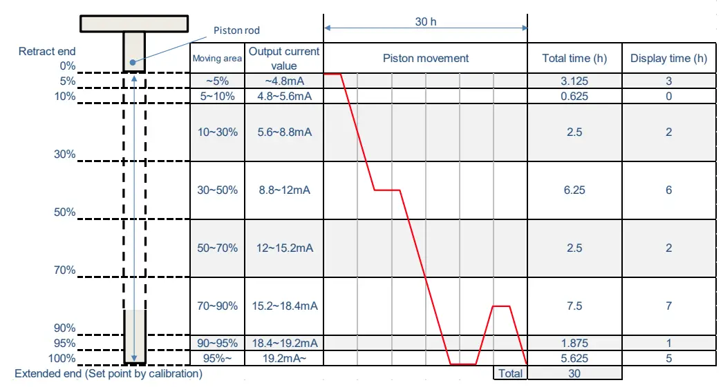
| Movement area | You can check the number of hours in a certain position of Air Servo Cylinder.*2 |
| Cal select status | Status can be selected: Calibration method selection status / normal operation status. |
| Cal type | Calibration type can be selected: Automatic / Manual. |
*1 Rod friction count indicates the number of times an abnormal stop of the piston rod occurred such as stick-slip.
*2 Movement area indicates the duration for the operating piston to remain in a specified range.
The range covers from the retracted end (0%) to the calibration set point (100%). The range is divided into 8 sections. The duration for which the piston remains (during both operating and stopping) in the specified area is recorded for 1 hour by the controller.
![]() Caution
Caution
If the power supply voltage is disconnected before 1 hour has passed, the accumulated time (less than one hour) will be reset. For example, when the power supply voltage is stopped for 1 hour and 45 minutes, the accumulated time will be 1 hour. When the power supply voltage is turned on again, the accumulation starts from 1 hour. When calibration is performed again, the recorded data is reset.
(Recording example)
HART Communication
![]() Caution
Caution
- Refer 475 field communicator manual from EMERSON for 475 field communication usage.
- Unless input current 4 to 20mADC is supplied to IN-777 Air Servo Cylinder, HART communication is not available.
IN-777 Air Servo Cylinder
This manual describes the version below. Communication may not be available if version is not the same. HART Universal command revision: 7
475 Field Communicator
If operate IN-777 Air Servo Cylinder with 475 field communicator, perform “Check for Updates” in “475 Easy Upgrade Programming Utility” to register IN-777 Air Servo Cylinder data to 475. (Refer 475 field communicator manual from EMERSON for details). When IN-777 Air Servo Cylinder is not registered yet, contact SMC. Update 475 field communicator firmware and module upon necessity.
Electrical wiring
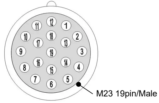
Perform wiring according to the connector pin numbers and the wiring diagram.
1. Connector pin numbers (Male side)
| Pin No. | Signal name | Input/output status | Description |
| 1 | Sig-in+ | Input | 4-20mA analog input signal (+) with HART |
| 2 | Sig-in- | Input | 4-20mA analog input signal (-) with HART |
| 3 | JOG+(*1) | Input | JOG operation signal (Move to the extended end direction) |
| 4 | JOG-(*1) | Input | JOG operation signal (Move to the retracted end direction) |
| 5 | PWR_24VDC | +24 VDC Power supply | |
| 6 | PWR_GND | Power supply GND | |
| 7 | Pos-out+ | Output | 4-20 mA analog output signal (+) |
| 8 | Pos-out- | Output | 4-20 mA analog output signal (-) |
| 9 | CTR | Output | Controller normal signal |
| 10 | CYL | Output | Positioning sensor error signal |
| 11 | VAL | Output | Valve error signal |
| 12 | GND_I/O | ― | Input/output signal GND |
| 13 | CAL(*1) | Input | Calibration signal |
| 14 | E-STOP | Input | Emergency stop signal (Negative edge triggered *2) |
| 15 | – | – | – |
| 16 | RF | Output | Piston rod friction error signal |
| 17 | PWR | Output | Power supply error signal |
| 18 | – | – | – |
| 19 | – | – | – |
*1 JOG+, JOG- and CAL are valid when the Operation mode (Menu Tree No.1-3-5-2) is in 4-20mA mode.
*2 Emergency stop is performed when signal is OFF.
2. Wiring diagram (Number in brackets indicates the pin numbers)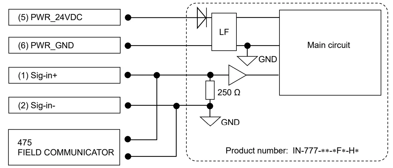
HART Communication Method
![]() Caution
Caution
Confirm followings before starting HART communication.
- Air Servo Cylinder IN-777 is supplied with 24V as input voltage.
- Air Servo Cylinder IN-777 is supplied with 4 to 20mA as input current.
- 475 field communicator wiring is arranged.
- Refer 475 field communicator manual from EMERSON for 475 field communication usage.
Procedure to start HART communication
Wire 475 field communicator to input current to IN-777 Air Servo Cylinder, and turn on the power supply of 475 field communicator. After starting 475 field communicator’s OS, synchronization with the Air Servo Cylinder automatically starts.
Setting
This model performs setting of normal/reversed switching of the piston rod travel direction during the target position operation; cylinder bore size, piston rod operating direction at no signal operation and piston rod speed during the target position operation by Air Servo Cylinder switch and HART communication. The setting by each method is explained below.
- Setting by Air Servo Cylinder switch
Refer “6. Setting” of operation manual of “Air Servo Cylinder (No.K35-OMW0030)”. - Setting by HART communication
Direction (Menu Tree No.1-3-5-3-1), Bore setting (Menu Tree No. 1-3-5-3-2), No signal operation (Menu Tree No.1-3-5-3-3) and Max speed (Menu Tree No.1-3-5-3-4) are available by setting the Operation mode (Menu Tree No.1-3-5-2) to Parameter mode. When the body power supply is turned OFF and power is applied again, the switch setting of the Air Servo Cylinder body is enabled.
2-1. Direction (Menu Tree No.1-3-5-3-1)
| Setting | Relationship between the analogue input signal and the piston rod movement direction |
| Cal Pos set to 20mA | 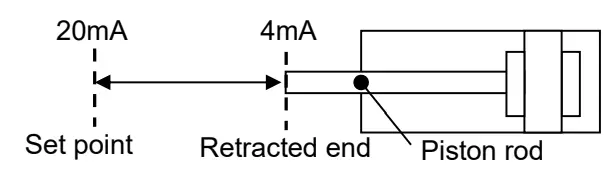 |
| Cal Pos set to 4mA | 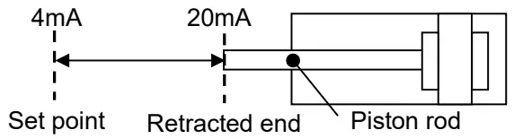 |
2-2. Bore setting
With Bore setting (Menu Tree No.1-3-5-3-2), the bore size of the Air Servo Cylinder used can be set. The available bore sizes are ø125, ø160, ø200, ø250, ø320 and ø400.
2-3. No signal operation
With No signal operation (Menu Tree No.1-3-5-3-3), the piston rod operation can be set when the input signal of 3.5mA or less is input. The available operation is Retracted end. Calibration position and Stay.
2-4. Max speed
With Max speed (Menu Tree No.1-3-5-3-4), the maximum operating speed of the piston rod can be set. The relation between the set value and speed is shown in the table below.
| setting No. | |||||||||
| 0 | 1 | 2 | 3 | 4 | 5 | 6 | 7 | 8 | 9 |
| Slower | →→(Speeds up gradually.)→→ | Faster | |||||||
![]() Caution
Caution
When setting the cylinder bore size, set the cylinder bore size of the body (IN-777) used.
When different bore size is set, vibration may occur or piston rod positioning may fail.
11. Operation Mode and Functions
This model can set the JOG operation, Calibration and Emergency stop by Air Servo Cylinder signal input and HART communication. The operation with each method is explained below.
- JOG operation, Calibration and Emergency stop operation by Air Servo Cylinder input signal When JOG operation and Calibration are performed by Air Servo Cylinder input signal, set the operation mode (Menu Tree No.1-3-5-2) to 4-20mA. Emergency stop is valid for all the setting of Operation mode (Menu Tree No.1-3-5-2). Refer to 7-1. JOG Operation, 7-2 Calibration and 7-5 Emergency Stop of the operation manual (K35OMW0030) for the signal input method of each operation.
- Operation by HART communication
2-1 JOG operation
Set the Operation mode (Menu Tree No.1-3-5-2) to JOG.
Each operation is performed by setting JOG operation (Menu Tree No.1-3-5-4-3) to Stop, Extend and Retract. The default setting is Stop.
If JOG operation is set to Extend or Retract when Operation mode is set to JOG, perform Stop once and then perform Extend and/or Retract.
2-2 Calibration
The piston rod movement range (set point) can be set when using the Target position operation (refer to 7-3). By performing the Calibration, the relationship between the piston rod position (from the retracted end to the set point) and the current value (4-20 mA) input to Sig-in+ and Sig-in- can be set.
Once the Calibration is performed, the set point is stored in the product and will be recorded even when the power supply is OFF.
There are two types of Calibration mode; Automatic and Manual.
The set point is not set when the product is shipped from the factory.
For how to change the calibration mode (Automatic mode or Manual mode), refer to the 7-2-1.
Change the mode Operation manual (K35-OMW0030).
2-2-1 Auto calibration
Set the Operation mode (Menu Tree No.1-3-5-2) to JOG.
Auto calibration is performed by turning ON the Calibration (Menu Tree No.1-3-5-4-2). The position at which the piston rod must stop for 1 second, due to an external stopper or cylinder extended end, is set as a set point. The default Calibration setting is OFF.
2-2-2 Manual calibration
Set the Operation mode (Menu Tree No.1-3-5-2) to JOG.
Perform JOG operation (Menu Tree No.1-3-5-4-3) by turning ON Extend or Retract to move the piston rod to the required stop position by turning ON Stop (example: position where an external stopper is located). When the calibration is ON, the position where the piston rod stops is set as a set point. The default Calibration setting is OFF.
If Calibration is ON after setting the Operation mode to JOG, turn OFF the Calibration once and turn it ON again.
2-3 Emergency stop
Emergency stop is performed by turning OFF the E-Stop off (Menu Tree No.1-3-5-4-1). Emergency stop is valid for all the setting of Operation mode (Menu Tree No.1-3-5-2). The default setting is OFF.
4-20 mA mode
When the operation (Target position operation) where the cylinder is operation by input current (4-20mA)
is performed, set the Operation mode (Menu Tree No.1-3-5-2) to 4-20mA. Refer to 7-3. Target Position Operation for the signal input method.
No signal operation
When an analog input signal of 3.5 mA or less is input, the piston rod operates according to the No signal operation setting set beforehand (Refer to 10.Setting “1. Setting by Air Servo Cylinder switch” or “2-3. No signal operation”).
Error status
Error status (Menu Tree No.1-3-4) and the descriptions are shown below.
| Error code | Error name | Possible causes | Countermeasures |
| 0 | No error | ||
| 1 | Power supply error (Outside of 24 V+/-10%) | The power supply voltage between the power supply terminal PWR_24V and PWR_GND is outside of 24 VDC +/-10%. | Use a power supply voltage of 24 VDC+/-10%. |
| 2 | Power supply error (Below 17 V) | The power supply voltage between the power supply terminal PWR_24V and PWR_GND is below 17 V. | Use a power supply voltage of 24 VDC+/-10%. |
| 3 | Incorrect cylinder bore size setting | All DIP switches No. 2, 3 and 4 are ON or OFF, which is an incorrect setting. | Change the setting of the DIP switch correctly. (Refer to operation manual K35-OMW0030). |
| 4 | Over current to the positioning sensor | Over current flowed to the positioning sensor. | Refer to *1. |
| 5 | Incorrect positioning sensor signal | Non-conformance occurred in the connection of the positioning sensor and controller or on the positioning sensor signal. | |
| 6 | Incorrect positioning sensor connection | Non-conformance occurred in the connection of the positioning sensor and controller. | Remove the controller to confirm that the connector of the sensor harness which connects the controller board and the positioning sensor is mounted correctly. |
| 7 | Over current to the emergency stop valve | Over current flowed to the emergency stop pilot valve (E- STOP valve). | Replace the emergency stop pilot valve. (Refer to *1.) |
| 8 | Over current to the servo valve | Over current flowed to the servo valve. | Replace the servo valve. (Refer to *1.) |
| 9 | Incorrect servo valve connection | Non-conformance occurred in the connection of the servo valve and controller. | Remove the controller to confirm that the connector of the valve harness which connects the controller board and the valve unit is mounted correctly. |
| A | Piston rod friction | Malfunction occurred in the piston rod. | Check the condition of the rod, and remove unbalanced load and/or foreign matter as necessary. |
| B | Controller error | Non-conformance occurred in the controller. | Refer to *1. |
Trouble shooting
If any irregular operation is found during the usage of this Air Servo Cylinder, perform countermeasures in the below table of troubleshooting. For troubles due to cause other than HART communication, refer “9. Trouble Shooting” of operation manual of “Air Servo Cylinder (No.K35-OMW0030)”.
| Content | Possible cause | Countermeasure | Page to refer |
| Communication not available | 475 communicator is not connected | Connect input current line with 475 field communicator | 13 |
| Air servo cylinder’s polling address is set other than “0” | Change the setting of 475 field communicater | 8 | |
| Input current is not stabilized | Ground the air servo cylinder | – | |
| Upper status controller does not match | Change upper status controller | – | |
| Input current is not applied | Apply correcct input current(4 to 20 mADC) | 13 | |
| Other cause | Contact SMC | – | |
| Setting change not available | Operation is in 4-20mA mode or JOG mode | Change operation mode to parameter mode | 15 |
| Other cause | Contact SMC | – |
Revision history
1st edition: March 2019
Rev. A: November 2019 (Partial correction)
Rev. B: May 2022 (Add Software rev.)
SMC Corporation
4-14-1, Sotokanda, Chiyoda-ku, Tokyo 101-0021 JAPAN
Tel: + 81 3 5207 8249 Fax: +81 3 5298 5362
URL http://www.smcworld.com
NOTE: Specifications are subject to change without prior notice and any obligation on the part of the manufacturer.
© 2022 SMC Corporation All Rights Reserved


