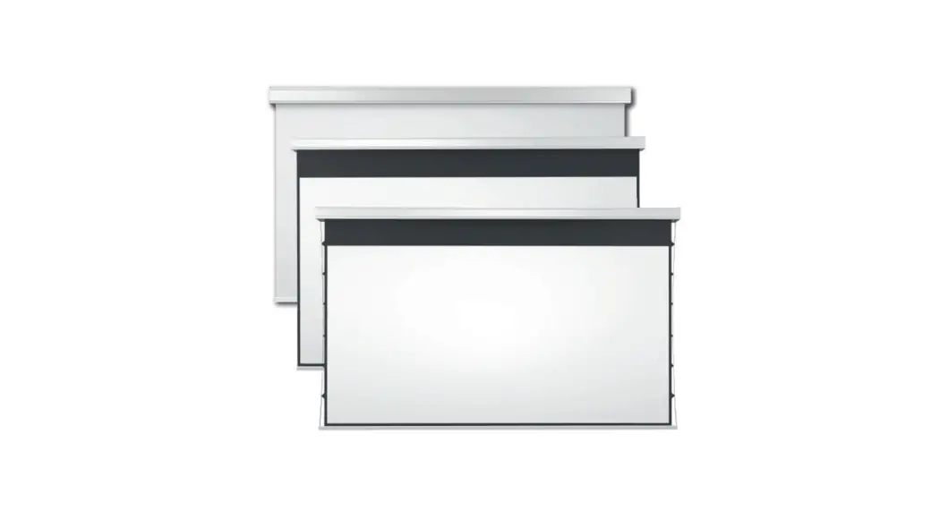
![]() Big Lodo Evolution
Big Lodo Evolution
Instruction Manual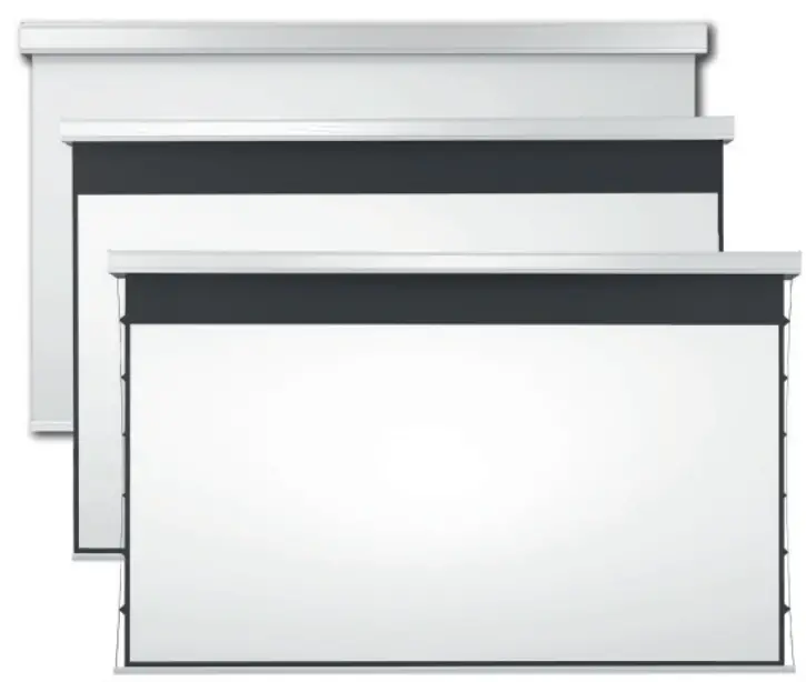
Place the empty packaging in the installation room making sure that the screen is positioned with its front side in the right direction.

Unpackaged the screen

![]() The installation must be carried out by qualified staff: the team in charge will have to unload, hoist and anchor the screen and connect the wiring.
The installation must be carried out by qualified staff: the team in charge will have to unload, hoist and anchor the screen and connect the wiring.![]() The improper installation of the system may damage the motor and the control system. The installation not in compliance with the given instructions will nullify the warranty!
The improper installation of the system may damage the motor and the control system. The installation not in compliance with the given instructions will nullify the warranty!![]() DURING THE HOISTING PROCESS IT IS STRICTLY FORBIDDEN TO WALK IN THE AREA UNDERNEATH THE SCREEN. ANY MISTAKE IN THE INSTALLATION OF THE SYSTEM COULD BE FATAL!
DURING THE HOISTING PROCESS IT IS STRICTLY FORBIDDEN TO WALK IN THE AREA UNDERNEATH THE SCREEN. ANY MISTAKE IN THE INSTALLATION OF THE SYSTEM COULD BE FATAL!![]() Any divergence from the procedures laid out in this manual will not be covered by the warranty.
Any divergence from the procedures laid out in this manual will not be covered by the warranty.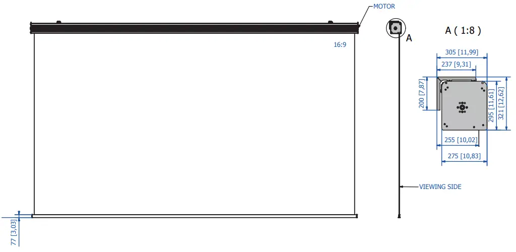
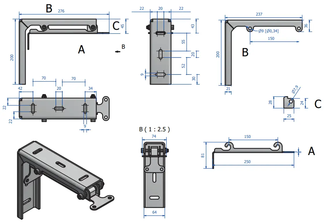
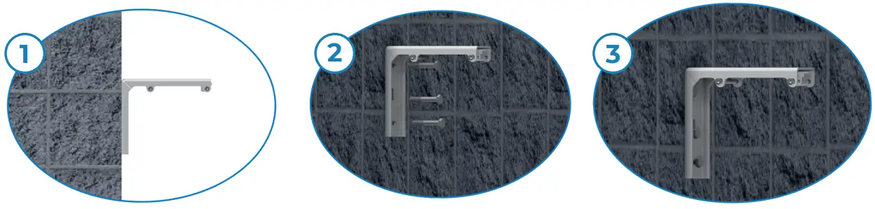
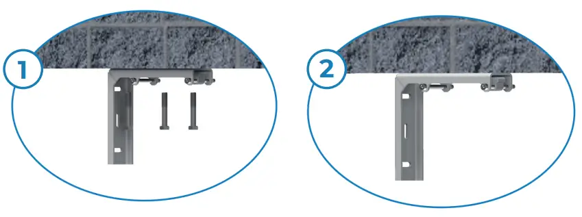
Wall brackets installation
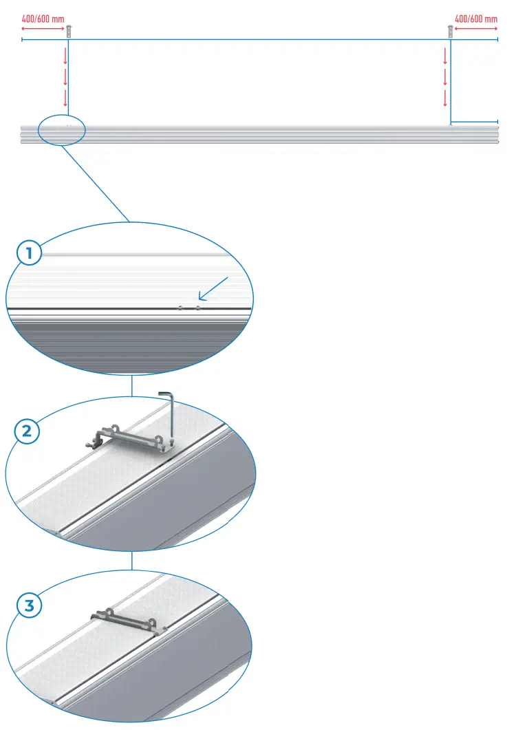
Install brackets according to the indication 400/600 mm.
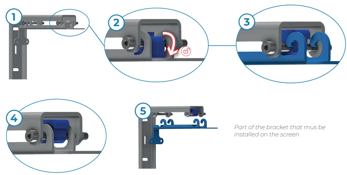
The screws will be already in the correct position 400/600 mm. Install the part of the bracket that must be installed on the screen in the same position as the screws.
Ceil brackets installation
Screen installation
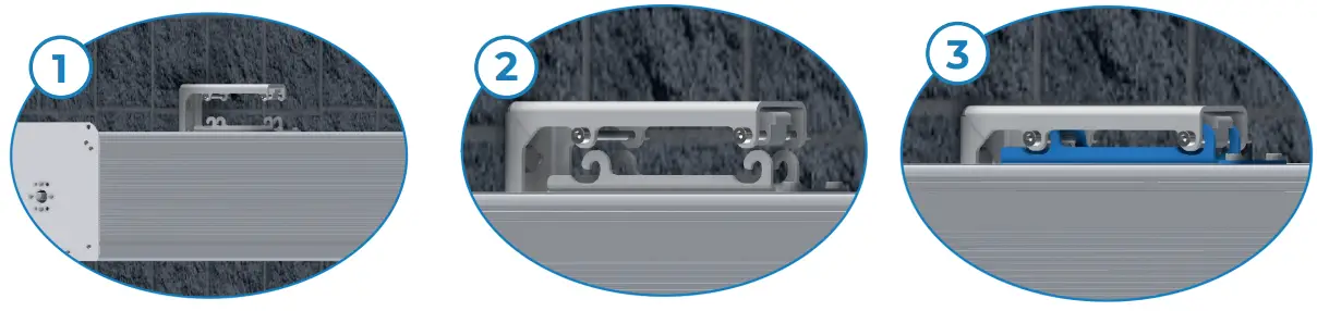
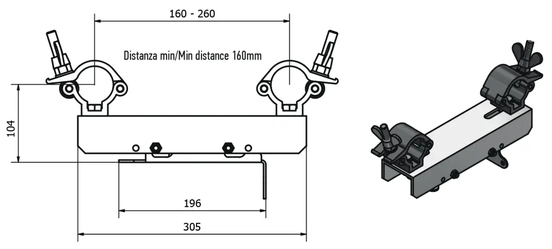
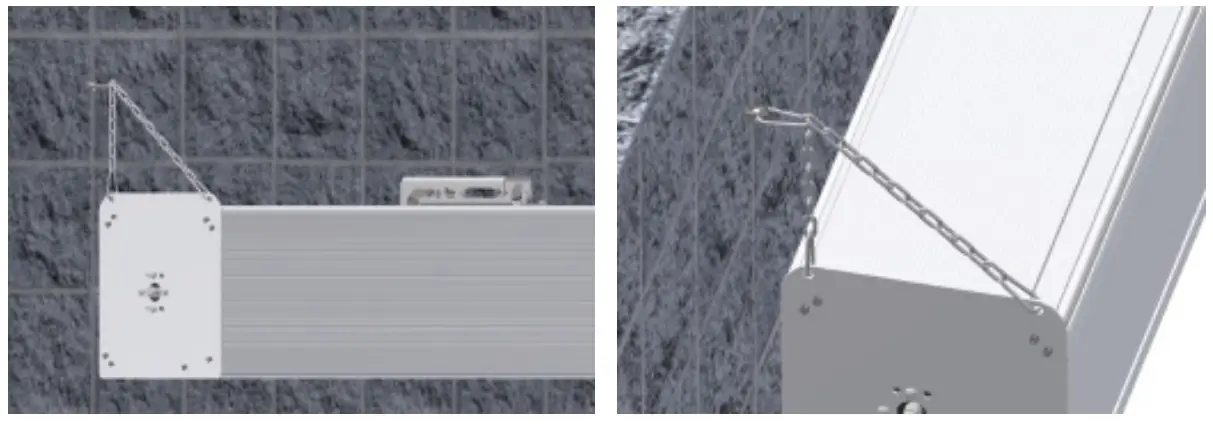
In case of truss installation: Aliscaf brackets
Remove the lower part of the bracket.
See page 4 to install the lower part of the bracket to the screen
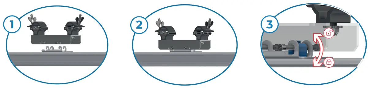
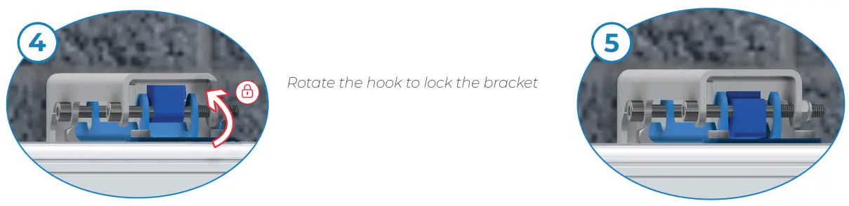
Rotate the hook to open and close the bracket
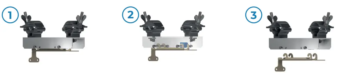
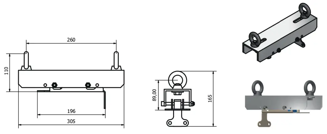
Eyebolt bracket
Remove the lower part of the bracket.
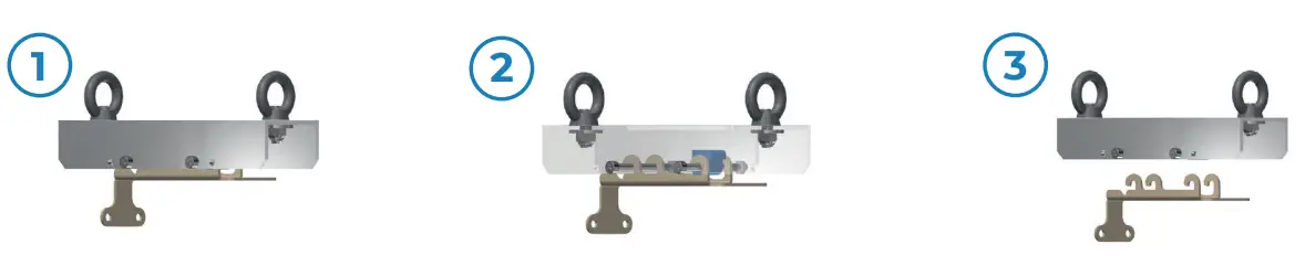
See page 4 to install the lower part of the bracket to the screen
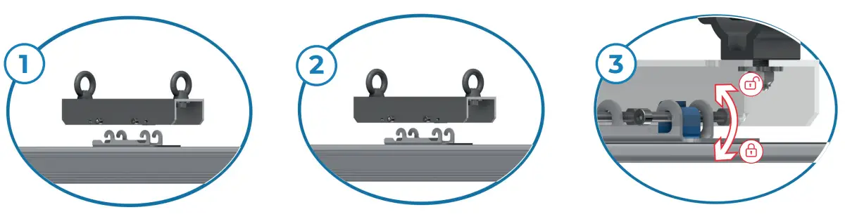
Rotate the hook to open and close the bracket
Wall safety chains
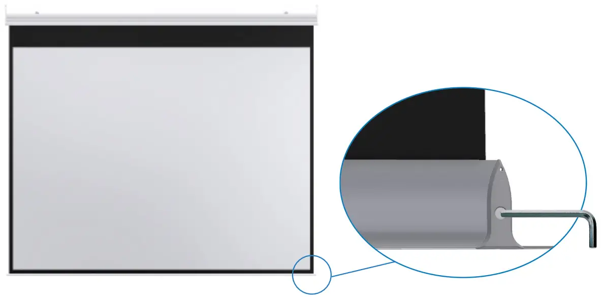
Regulation of the counterweight in order to flat the fabric. Just in case of waves.
![]() WARNING
WARNING
The PVC fabric is very sensitive to heating. In a very hot environment, the fabric can be softer excessively and stretch down by altering the video ratio. You should absolutely avoid placing the screen in front of sunlit windows or above radiators, fireplaces, and stove of all kinds. The higher will be the heating absorbed by the screen, the higher will be the deformation of the surface which will assume an elongated shape with curved lateral edges.
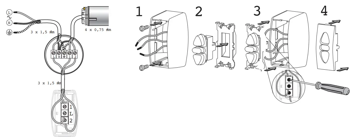
| TERMINALS | POWER SUPPLY | MOTOR (EUR) | MOTOR (US) |
| L | PHASE (L) | ||
| N | NEUTRAL(N) | BLUE | WHITE |
| W | EARTH (W) | YELLOW/GREEN | GREEN |
| 1 | BLACK OR BROWN | BLACK OR RED | |
| 2 | BLACK OR BROWN | BLACK OR RED | |
| – Disconnect the main supply before carrying out any work. – Ensure that no forces act on terminals after installation. – Connect the earth wires before phase and neutral. | |||
ELETTRONICO LIMIT-SWITCH PROGRAMMING UNIT
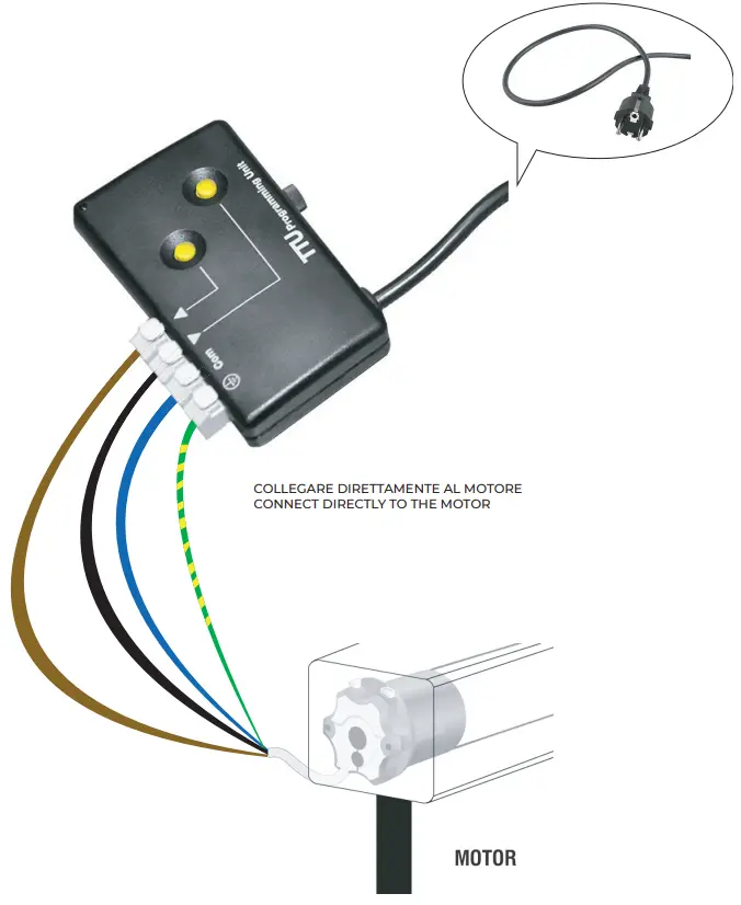
INFERIOR LIMIT POINTS’ CHANGING![]() WARNING: When delivered, the motor is set on “working” mode. To change the set points it is necessary to proceed with the cancellation of the points set by the manufacturer.
WARNING: When delivered, the motor is set on “working” mode. To change the set points it is necessary to proceed with the cancellation of the points set by the manufacturer.
IT IS ESSENTIAL NOT TO MODIFY THE DOWN LIMIT POINT SET BY THE MANUFACTURER OVER ± 10 CM.
(Otherwise, the warranty shall not apply)
- Open the screen to the middle position;
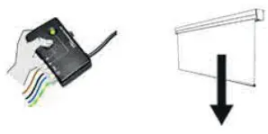
- CLEAR ALL ADJUSTMENTS
(This can only be done using a double button that is not interlocked)
Press UP AND DOWN at the same time for 8”, until the screen moves UP AND DOWN 2 times.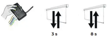
- ENTER PROGRAMMING MODE
Press UP and DOWN simultaneously until the screen moves UP and DOWN Press UP and DOWN at the same time for 8”, until the screen moves UP AND DOWN 2 times.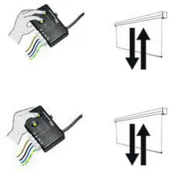
- ADJUSTMENT OF THE DOWN LIMIT SWITCH
Pressing DOWN, bring the screen to the down limit point
Pressing DOWN, bring the screen to the down limit Press UP quickly, release and press RISE again for 3”, until the screen moves UP and DOWN.
Press UP quickly, release and press RISE again for 3”,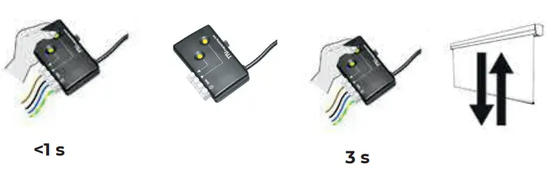
- STORAGE OF THE LIMIT SWITCH
Press UP AND DOWN at the same time for 3”, until the screen moves UP AND DOWN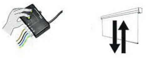
NOTE …………………………
Screenline Srl – Via Nazionale 1/n 38060 Besenello (TN) Italy
+39 0464 830003
www.screenline.it
[email protected]


