![]()
C800 general instructions
 Reminder: All photos here are for reference only, Specifications are subject to the physical product.
Attention
- An abnormal situation occurs during operation, please press the reset key on the panel to restore factory settings.
- When the in-car temperature is much higher or lower, please adjust the temperature inside the car first before using this machine.
- Avoid strong shocks because they can damage the mechanical parts and structural components.
- This machine is composed of high-precision parts, please do not dismantle the machine cover or adjust any parts, if you need maintenance please go to the professional after-sales service center to accept the service.
- Please follow the instruction manual, the damage caused by the illegal operation is not in the warranty scope.
Specification
SNR………… 65dB
Frequency response ……………20Hz-20KHz
Loudspeaker impedance ………..40_80
The maximum output power……….. 4*60W
Tone Control ………..Bass+/-7dB(100Hz) Treble+/-7d6(100Hz)
FM FM frequency…………… 87.5MHz-108MHz
Sensitivity ……………25dB
Selectivity ……………..60dB
Separation ………………………35dB
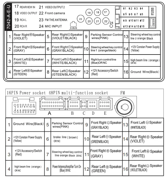
wiring diagram
9-inch Screen installation method
- Open
- Insert a flat cable
- Close
- Pull the retaining clip apart
- Adjust angle
*9″special-purpose
Function brief
- Support the Audio playback format of MP3/WMA/WAV/ M KV/FLAC/OGG/APE.
- Support the Video playback format of RM/RMVB/DVD(V0B)/ VCD( DAT)/M Pl/M P2/DIVX/XVID/MP4/H263/H264/FLV/3G P/ SWF/AVI/ASF/MJPEG etc;
- Support the picture formatofJPG BMP PNG etc
- Rearview camera Function
- Right turn blind area detection function
- HD digital TFT screen
- Multi-screen display
- Two-channel video output
- Two-channel audio output
- One channel audio and video input interface
- Super-clear FM radio can store 6 stations, support AM, RDS function
- Clock Function
- With Remote Control
- Support memory card,U disk
- Song Name Display Function
- File navigation
- Power-off memory function
- Firmware upgrade
- Colorful lamp
- BTfunction
- Touch function
Basic operations:
- Rearview function: Input the video signal of the rearview camera from the corresponding rearview terminal, the line of the reversing lamp is connected to the reversing control line of the machine, the reverse image state is automatically switched back image status.
- Visual function of the right-turning blind area: Connect the video signal of the right steering camera to the corresponding video input terminal, Connect the right turn light line to the machine right turn detection line, When the car turns right on, it automatically switches to the right Blind Area Image Function.
- Multi-screen Same Display Function: 1. Connect the video output terminal of the host computer to the video input terminal requiring the same display device,so that the picture of the host computer can be displayed at the same time, Multiple devices can be supported for simultaneous display.
- Audio and video input function: 1 Connect audio and video devices that need input to the host AUX input interface, and select the AUX function in the host interface.
|
|
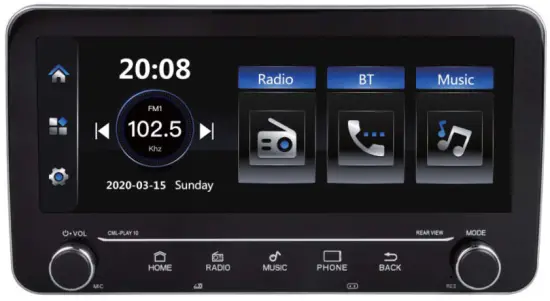
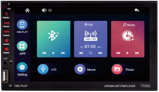
Main interface
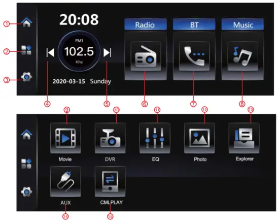
| 1. HOME 2. Functional area 3. Setting 4. Last song 5. Next song 6. Radio 7. BT Call | 8. Music 9. video 10. DVR 11. EQ 12. picture 13. folder 14. AUX-IN 15.PhoneLink |
- Radio mode
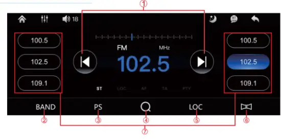
| 1. Forward/backward search 2. Band switching 3. Autosave 4. Automatic search 5. Local radio station 6. Long and short-range switching 7. Short press to play the saved station, long press to save the current station 8. Cycle mode 9. High and low bass settings |
2. Music mode 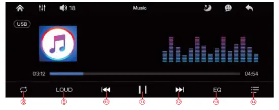
| 10. Last song 11.Play / pause 12. Next song 13.EQ settings 14.playlist |
BT Mode
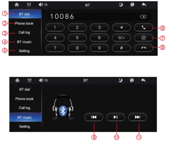
| 7. Hang up 8. Last song 9.Play / pause 10. Next song |
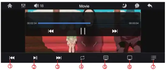
Video mode
5.EQ mode
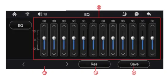
| 7. Playlist 12. EQ range 13. Style adjustment 14. Restore initial settings 15. Save current settings |
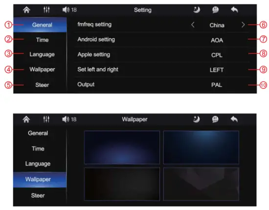
Seating
|
|
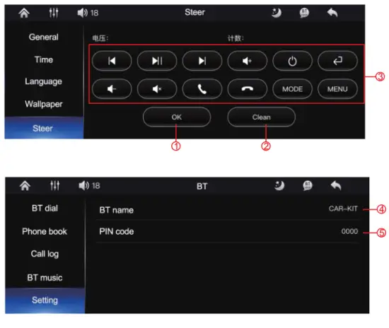
- 0K button
- Clear current settings
- Learning button, first click the button on the screen and then press the corresponding button on the remote control
- BT name
- Connection password
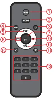
Function panel presentation.
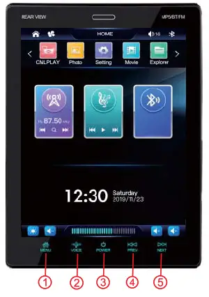
| 1. MENU |
| 2. VOICE |
| 3. POWER |
| 4. PREV |
| 5. NEXT |
| 6. MODEL 7.BACK8 |
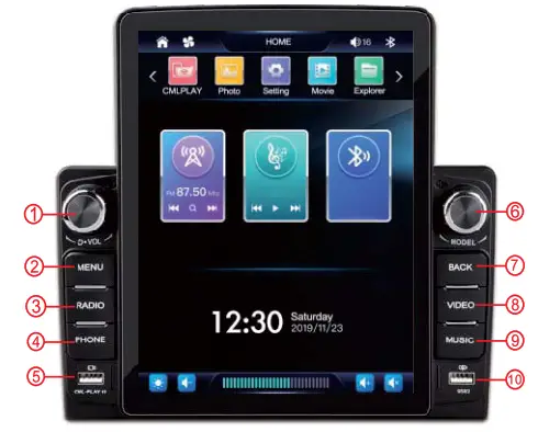
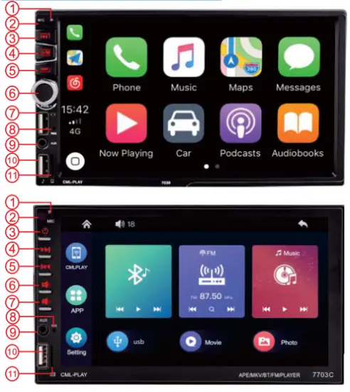
7. Function panel presentation.
|
|
|
|
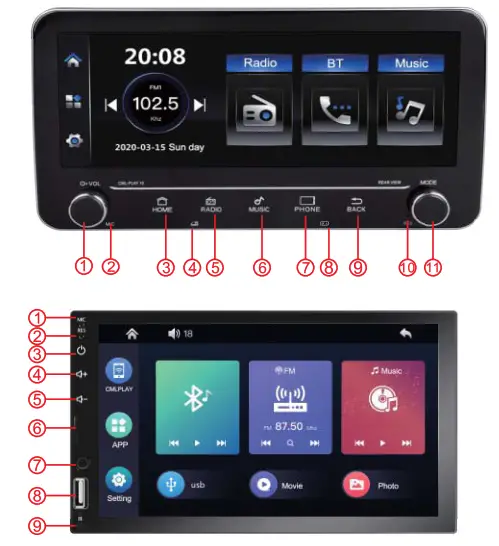
| 1. MIC 2. IR 3. POWER 4. PREV 5. NEXT 6.VOL+ | 7. VOL- 8. RES 9. AUX 10. USB 11. Card slot |
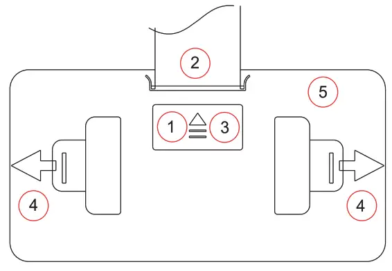
Screen installation method
| 1. MIC | 6. Card slot |
| 2. RES | 7. AUX |
| 3. POWER | 8. USB |
| 4.VOL+ | 9. IR |
| 5. VOL- |
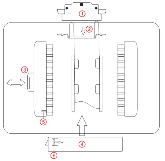
- Remove the cable cover The fingers are pulled straight out at the black spot above, Press the black spots on both sides during installation
- 1nsert the cable into the outlet Press down the flat wire by facing the winding mouth To take out the cable, you need to press the buckle on both sides and pull it outward
- Open the manual baffle
- Align the slots of the host and the screen, Then push the main engine up Push to the right position and then press the manual baffle
- Antiskid baffle
- Nonslip buckle You need to push the buckle to remove the screen completely
C800 general instructions
Thank you for your use
This device complies with part 15 of the FCC Rules. Operation is subject to the following two conditions: (1) this device may not cause harmful interference, and (2) this device must accept any interference received, including interference that may cause undesired operation. Any changes or modifications not expressly approved by the party responsible for compliance could void the user’s authority to operate the equipment.
NOTE: This equipment has been tested and found to comply with the limits for a Class B digital device, pursuant to Part 15 of the FCC Rules. These limits are designed to provide reasonable protection against harmful interference in a residential installation. This equipment generates, uses and can radiate radio frequency energy and, if not installed and used in accordance with the instructions, may cause harmful interference to radio communications. However, there is no guarantee that interference will not occur in a particular installation. If this equipment does cause harmful interference to radio or television reception, which can be determined by turning the equipment off and on, the user is encouraged to try to correct the interference by one or more of the following measures:
— Reorient or relocate the receiving antenna.
— Increase the separation between the equipment and receiver.
— Connect the equipment into an outlet on a circuit different
from that to which the receiver is connected.
— Consult the dealer or an experienced radio/TV technician for help.
The device has been evaluated to meet general RF exposure requirements. The device can be used in portable exposure conditions without restriction


