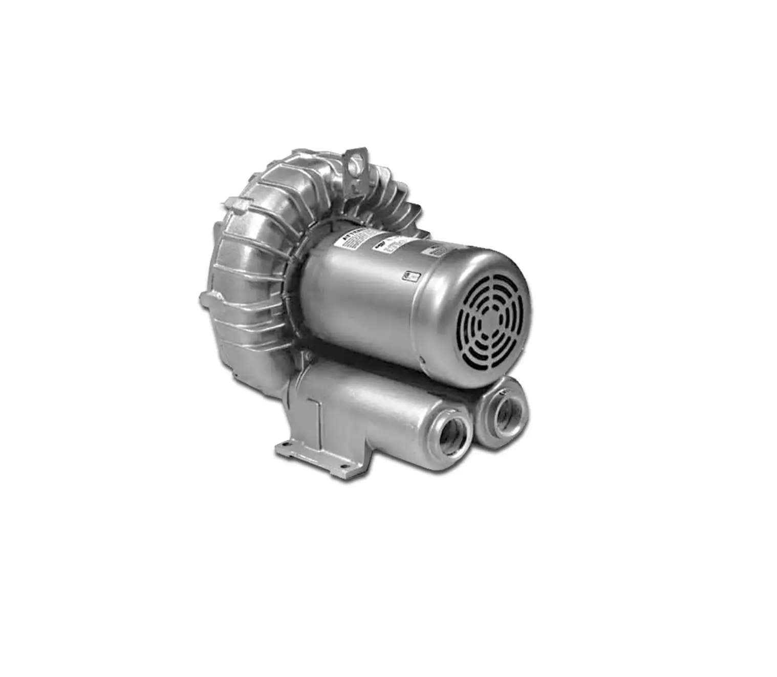
GAST R6P350A Standard Regenair Blower
Thank you for purchasing this Gast product. It is manufactured to the highest standards using quality materials. Please follow all recommended maintenance, operational and safety instructions and you will receive years of trouble free service.
| |
 | PLEASE READ THIS MANUAL COMPLETELY BEFORE INSTALLING AND USING |
General information
This manual does not apply to:
- SDR Series blowers without motors
- Blowers powered with Explosion Proof Motors
Product Use Criteria:
- Pump only clean, dry air.
- Operate at -20ºF – 104ºF (-29ºC – 40ºC).
- Protect unit from dirt & moisture.
- Do not pump flammable or explosive gases or use in an atmosphere that contains such gases.
- Protect all surrounding items from exhaust air. This exhaust air can become very hot.
- Corrosive gases and particulate material will damage unit. Water vapor, oil-based contaminants or other liquids must be filtered out.
- The blower must be installed with the properly sized inlet and inline filters, gauges and relief valves to protect the product from dirt and over-heating.
- Consult your Gast Distributor/Representative before using at high altitudes.
Your safety and the safety of others is extremely important. We have provided many important safety messages in this manual and on your product. Always read and obey all safety messages. |
 This is the safety alert symbol. This symbol alerts you to hazards that can kill or hurt you and others. The safety alert symbol and the words
| You will be killed or seriously injured if you donʼt follow instructions. |
| You can be killed or seriously injured if you donʼt follow instructions. All safety messages will identify the hazard, tell you how to reduce the chance of injury, and tell you what can happen if the safety instructions are not followed. |
INSTALLATION
 |
Electrical Shock Hazard Disconnect electrical power at the circuit breaker or fuse box before installing this product. |
Correct installation is your responsibility. Make sure you have the proper installation conditions and that installation clearances do not block air flow.
Blocking air flow over the product in any way can cause the product to overheat.
The blower must be installed with the properly sized inlet filter, gauge and relief valve to protect the productfrom dirt and over-heating.
Mounting
The single impeller blower should be oriented with the shaft in a horizontal position, unless the modelʼs product features state otherwise. The dual impeller models must be mounted with the shaft in a horizontal position.
Mounting the product to a stable, rigid operating surface and using shock mounts will reduce noise and vibration.
Rotation
From the motor side of the blower, check that the blower is rotating clockwise. (The motor side is marked with an arrow on most models.) Proper rotation can also be checked by the air flow at the IN and OUT ports. On blowers powered by a 3-phase motor, incorrectly connecting any two power lines can reverse direction.
Pluxmbing
Remove any foreign material (burrs, chips, welding drops, slag, pipe cuttings, excess sealant, sand or lime) from plumbing.
Check motor mounting and rotation before connecting to plumbing. Inlet and outlet ports are not designed to support plumbing.
Remove plugs from the IN and OUT ports. Use a small amount of pipe thread lubricant when connecting plumbing to protect the aluminum blower threads.
Connect with pipe and fittings that are the same size or larger than the productʼs threaded ports. When installing two blowers in parallel, use plumbing that is two whole pipe sizes larger in diameter than that of the blower. Be sure to connect the intake and exhaust plumbing to the correct inlet and outlet ports.
Plumbing to remove the hot discharge air of larger blowers may be required to help maintain proper room ambient temperature. Use a relief valve to discharge excess air into the atmosphere. If the blower will be operated at 125mbar (50” H2O) or higher, metal pipe is required for hot exhaust air.
Accessories
Install two vacuum gauges, one before and one after filter, to monitor restriction through filters. As filters become clogged, performance efficiency will be reduced. Filters should be checked periodically and replaced when necessary. See page 7 for installation.
Install a relief valve to avoid changes in pressure or vacuum that can cause overloading of large blowers.
Install an intake filter with a relief valve to prevent foreign material from entering blower if blower is used in a vacuum application in a dirty environment. In applications where there is high humidity or liquids being used in the process, install a moisture separator.
See Recommended Accessories on pages 7-9 or consult your Gast Distributor/Representative for additional filter and accessories recommendations. Do Not install check valves that close with a strong spring.
The recommended check valves (page 7) provide minimal pressure drop, positive sealing and are resistant to the high discharge temperatures of large blowers.
Motor Installation
It is your responsibility to contact a qualified electrician and assure that the electrical installation is adequate and in conformance with all national and local codes and ordinances.
Select fuses, motor protective switches or thermal protective switches to provide protection. Fuses act as short circuit protection for the motor, not as protection against overload. Incoming line fuses must be able to withstand the motorʼs starting current. Motor starters with thermal magnetic overload or circuit breakers protect motor from overload or reduced voltage conditions. Motors without automatic restart require thermal protection or magnetic over-current cutout to prevent motor overloading from one phase in a 3-phasecircuit, high starting frequency or jammed blower.
The power required will rise as differential pressure increases. The wiring diagram attached to the product or on page 6 of this manual provides required electrical information. Large motors have two diagrams, one for 50Hz wiring specifications and the other for 60Hz wiring specifications. Check that the power source is correct to properly operate the dual-voltage motor. If additional information is required, please consult your Gast Distributor/Representative.
Electrical Connection
|
Electrical Shock Hazard This product must be properly grounded. |
Model with a power supply cord:
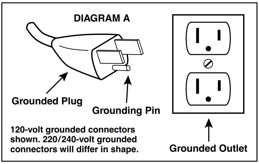
This product must be grounded. For either 120-volt or 220/240-volt circuits connect power supply cord grounding plug to a matching grounded outlet. Do not use an adapter. (See DIAGRAM A)
In the event of an electrical short circuit, grounding reduces the risk of electric shock by providing an escape wire for the electric current. This product may be equipped with a power supply cord having a grounding wire with an appropriate grounding plug. The plug must be plugged into an outlet that is properly installed and grounded in accordance with all local codes and ordinances.
Check with a qualified electrician or serviceman if the grounding instructions are not completely understood, or if you are not sure whether the product is properly grounded. Do not modify the plug provided. If it will not fit the outlet, have the proper outlet installed by a qualified electrician.
Model that is permanently wired:
This product must be connected to a grounded, metallic, permanent wiring system, or an equipment grounding terminal or lead on the product.
Power supply wiring must conform to all required safety codes and be installed by a qualified person. Check that supply voltage agrees with that listed on product nameplate.
Extension cords:
Use only a 3-wire extension cord that has a 3-blade grounding plug. Connect extension cord plug to a matching 3-slot receptacle. Do not use an adapter. Make sure your extension cord is in good condition.
Check that the gage wire of the extension cord is the correct size wire to carry the current this product will draw. An und
An undersized cord is a potential fire hazard, and will cause a drop in line voltage resulting in loss of power causing the product to overheat. The following table indicates the correct size cord for length required and the ampere rating listed on the product nameplate. If in doubt, use the next heavier gage cord. The smaller the gage number, the heavier the wire gage.
| Minimum gage for extension cords Amps Volts Length of cord in feet | |||||||||
120v | 25 | 50 | 100 | 150 | 200 | 250 | 300 | 400 | 500 |
240v | 50 | 100 | 200 | 300 | 400 | 500 | 600 | 800 | 1000 |
| 0-2 | 18 | 18 | 18 | 16 | 16 | 14 | 14 | 12 | 12 |
2-3 | 18 | 18 | 16 | 14 | 14 | 12 | 12 | 10 | 10 |
3-4 | 18 | 18 | 16 | 14 | 12 | 12 | 10 | 10 | 8 |
| 4-5 | 18 | 18 | 14 | 12 | 12 | 10 | 10 | 8 | 8 |
5-6 | 18 | 16 | 14 | 12 | 10 | 10 | 8 | 8 | 8 |
| 6-8 | 18 | 16 | 12 | 10 | 10 | 8 | 6 | 6 | 6 |
8-10 | 18 | 14 | 12 | 10 | 8 | 8 | 6 | 6 | 4 |
| 10-12 | 16 | 14 | 10 | 8 | 8 | 6 | 6 | 4 | 4 |
12-14 | 16 | 12 | 10 | 8 | 6 | 6 | 6 | 4 | 2 |
| 14-16 | 16 | 12 | 10 | 8 | 6 | 6 | 4 | 4 | 2 |
16-18 | 14 | 12 | 8 | 8 | 6 | 4 | 4 | 2 | 2 |
| 18-20 | 14 | 12 | 8 | 6 | 6 | 4 | 4 | 2 | 2 |
OPERATION
Injury Hazard Install proper safety guards as needed to prevent any close contact with blower suction area. |
It is your responsibility to operate this product at recommended pressures or vacuum duties and room ambient temperatures. Do not operate R4P or larger size blowers without air flowing through the blower. Do not throttle discharge or suction pipe to reducer capacity. Throttle will increase differential pressure causing increasing power absorption and working temperatures.
Start Up
Operate blower for an hour and then check:
- Ambient temperature – Check room and discharge air temperatures. Increased room temperatures may require stronger ventilation especially for larger blowers. Exhaust air should not exceed 215ºF (102ºC) for all blowers less than 3.5 Hp. Exhaust air should not exceed 275ºF (135ºC) for all blowers above 3.5 Hp.
- Working pressure and vacuum values – Adjust relief valve pressure or vacuum setting, if needed.
- Motor current – Check that supply current matches recommended current rating on product nameplate.
- Electrical overload cutout – Check that current matches rating on product nameplate.
If motor fails to start or slows down significantly under load, shut off and disconnect from power supply. Check that the voltage is correct for motor and that motor isturning in the proper direction.
FOR BLOWERS WITH GREASE FITTINGS
| Hours of Service Per Year | Relubrication Intervals |
| 5,000 | 3 years |
| Continual Normal Service | 1 year |
| Seasonal Service (motor idle for 6 months or more) | 1 year at beginning of season |
| Continuous-high ambients, dirty or moist applications | 6 months |
Check that all external accessories such as relief valves and gauges are not damaged before re-operating product.
MAINTENANCE
|
Electrical Shock Hazard Disconnect electrical power supply cord before performing maintenance on this product. |
Injury Hazard Product surfaces become very hot during operation, allow product surfaces to cool before handling. |
It is your responsibility to regularly inspect and make necessary repairs to this product in order to maintain proper operation. Make sure that pressure and vacuum is released from product before starting maintenance.
Check filter elements and noise absorbing foam used in mufflers and clean motor and blower after first 500 hours of operation. Replace filter elements and determine how frequently mufflers should be checked during future operation. This one procedure will help assure the productʼs performance and service life.
When there is an increase in the differential pressure across the inlet filter it is beginning to clog with dirt. Replace the cartridge when the filter will not come clean.
Small motor bearings (less than 5.5 Hp) never need to be greased. Larger motor bearings (greater than 5.5 Hp) have alemite grease fittings. Use a grease gun and apply one or two strokes of Exxon POLYREX® grease to the fittings to lubricate larger motor bearings.
WARRANTY
Gast finished products, when properly installed and operated under normal conditions of use, are warranted by Gast to be free from defects in material and workmanship for a period of twelve (12) months from the date of purchase from Gast or an authorized Gast Representative or Distributor. In order to obtain performance under this warranty, the buyer must promptly (in no event later than thirty (30) days after discovery of the defect) give written notice of the defect to Gast Manufacturing
Incorporated, PO Box 97, Benton Harbor Michigan USA 49023-0097 or an authorized Service Center (unless specifically agreed upon in writing signed by both parties or specified in writing as part of a Gast OEM Quotation). Buyer is responsible for freightcharges both to and from Gast in all cases.
This warranty does not apply to electric motors, electrical controls, and gasoline engines not supplied by Gast. Gastʼs warranties also do not extend to any goods or parts which have been subjected to misuse, lack of maintenance, neglect, damage by accident or transit damage.
THIS EXPRESS WARRANTY EXCLUDES ALL OTHER WARRANTIES OR REPRESENTATIONS EXPRESSED OR IMPLIED BY ANY LITERATURE, DATA, OR PERSON. GASTʼS MAXIMUM LIABILITY UNDER THIS EXCLUSIVE REMEDY SHALL NEVER EXCEED THE COST OF THE SUBJECT PRODUCT AND GAST RESERVES THE RIGHT, AT ITS SOLE DISCRETION, TO REFUND THE PURCHASE PRICE IN LIEU OF REPAIR OR REPLACEMENT.
GAST WILL NOT BE RESPONSIBLE OR LIABLE FOR INDIRECT OR CONSEQUENTIAL DAMAGES OF ANY KIND, however arising, including but not limited to those for use of any products, loss of time, inconvenience, lost profit, labor charges, or other incidental or consequential damages with respect to persons, business, or property, whether as a result of breach of warranty, negligence or otherwise. Notwithstanding any other provision of this warranty, BUYERʼS REMEDY AGAINST GAST FOR GOODS SUPPLIED OR FOR NON-DELIVERED GOODS OR FAILURE TO FURNISH GOODS, WHETHER OR NOT BASED ON NEGLIGENCE, STRICT LIABILITY OR BREACH OF EXPRESS OR IMPLIED WARRANTY IS LIMITED SOLELY, AT GASTʼS OPTION, TO REPLACEMENT OF OR CURE OF SUCH NONCONFORMING OR NON-DELIVERED GOODS OR RETURN OF THE PURCHASE PRICE FOR SUCH GOODS AND IN NO EVENT SHALL EXCEED THE PRICE OR CHARGE FOR SUCH GOODS. GAST EXPRESSLY DISCLAIMS ANY WARRANTY OF MERCHANTABILITY OR FITNESS FOR A PARTICULAR USE OR PURPOSE WITH RESPECT TO THE GOODS SOLD. THERE ARE NO WARRANTIES WHICH EXTEND BEYOND THE DESCRIPTIONS SET FORTH IN THIS WARRANTY, notwithstanding any knowledge of Gast regarding the use or uses intended to be made of goods, proposed changes or additions to goods, or any assistance or suggestions that may have been made by Gast personnel.
Unauthorized extensions of warranties by the customer shall remain the customerʼs responsibility.
CUSTOMER IS RESPONSIBLE FOR DETERMINING THE SUITABILITY OF GAST PRODUCTS FOR CUSTOMERʼS USE OR RESALE, OR FOR INCORPORATING THEM INTO OBJECTS OR APPLICATIONS WHICH CUSTOMER DESIGNS, ASSEMBLES, CONSTRUCTS OR MANUFACTURES.
This warranty can be modified only by authorized Gast personnel by signing a specific, written description of any modifications.
ELECTRICAL WIRING DIAGRAMS
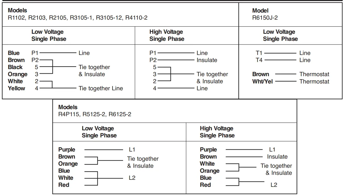
Models
R2303A, R3305A-1, R3305A-13, R4310A-2, R4P315A, R6350A-2, R6P350A, R6PP3110M, R6PS3110M, R7100A-3, R7P3180M, R7S3180M, R93150A
Note: Model R6P355A has two additional leads labeled “J” for an external thermal motor protection circuit.
Connections for 3-Phase, 9 Leads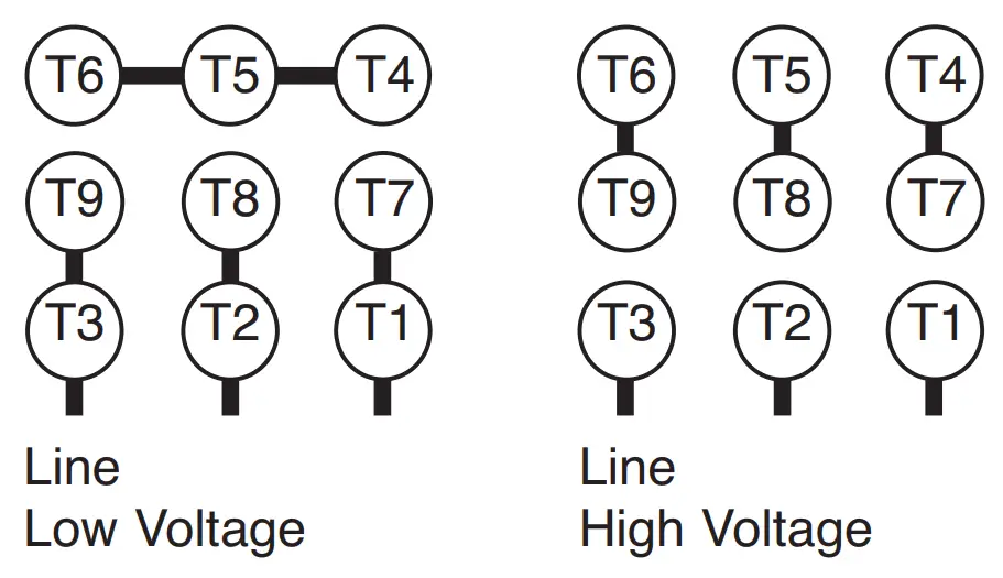
Connections for 3-Phase, 12 Leads Models R6335A-2, R6P335A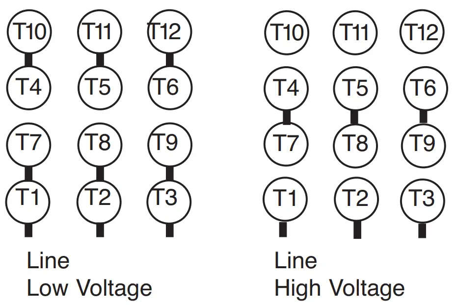
Model R9P3300M, R93150A, R93150A-35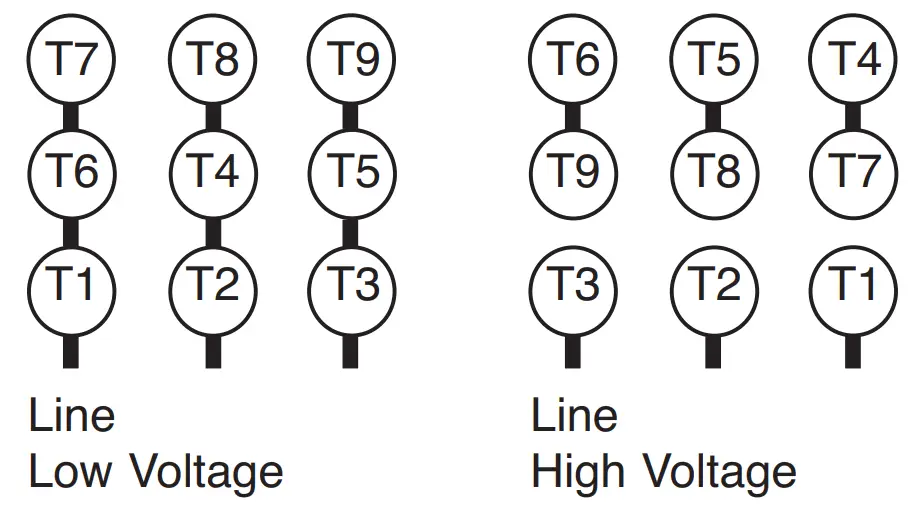
Models R5325A-2, R6325A-2 (BEFORE 1-1-06)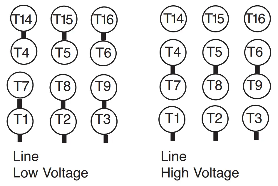
Models R5325A-2, R6325A-2 (AFTER 1-1-06)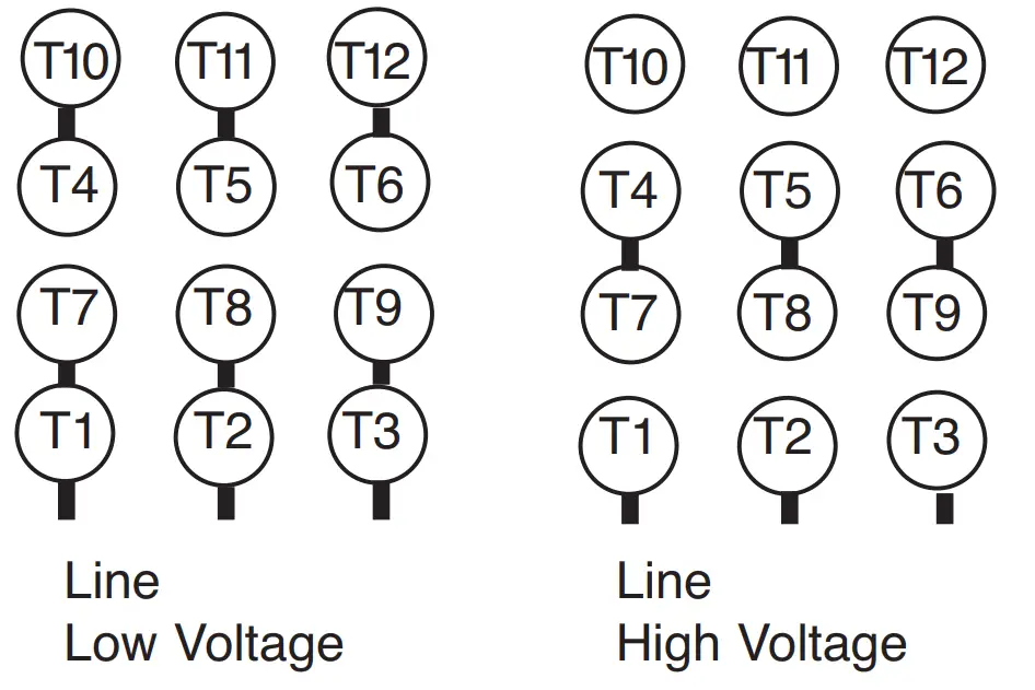
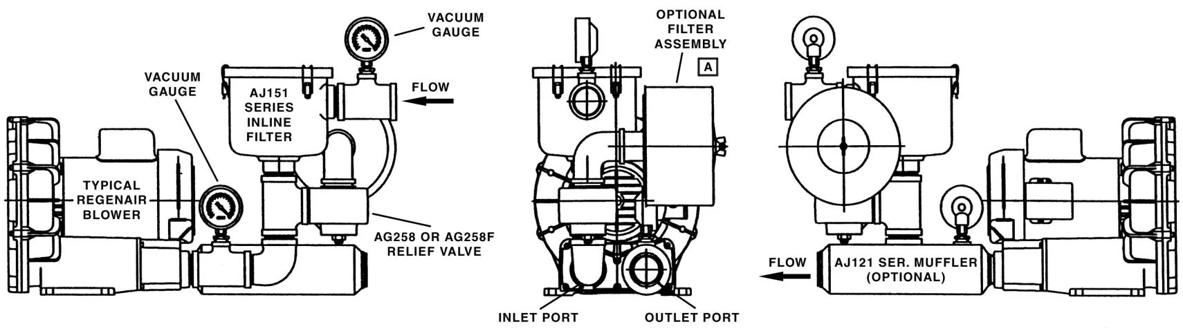
RECOMMENDED ACCESSORIES
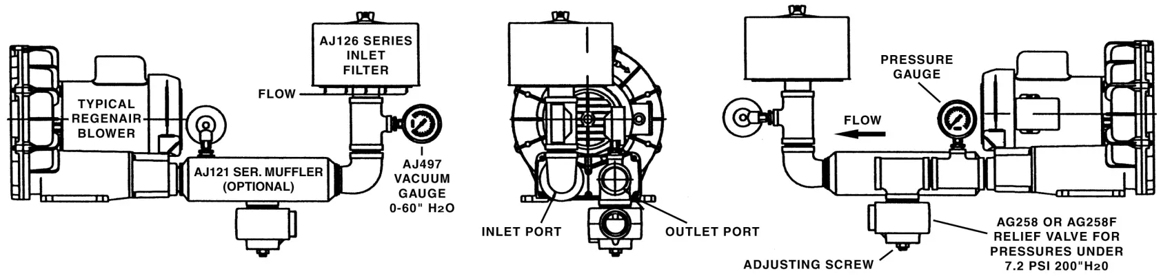
The following diagrams are only suggested configurations for these accessories. These accessory configurations may vary depending upon a particular unitʼs application.
VACUUM ACCESSORIES
PRESSURE ACCESSORIES
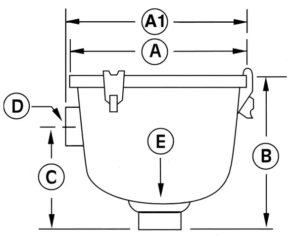
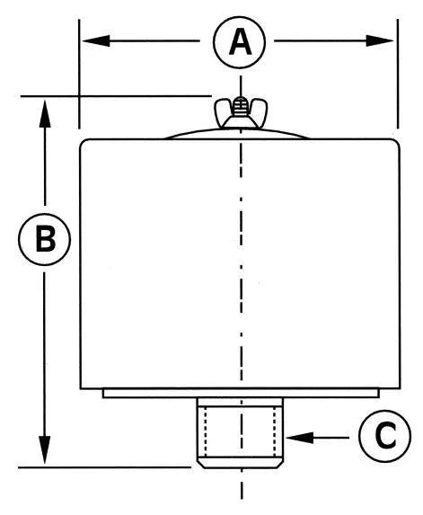
MOISTURE SEPARATOR (FOR VACUUM)
This moisture separator removes liquids from the gas stream in a vacuum process.
This helps protect the blower from corrosion and the build up of mineral deposits.
For Model Number | R3, R4, R5 | R4, R4H, R4P, R5 | R4H, R4M, R5, R6, R6P, R6PS, | R4M, R6, R6P, R6PP, R7, R7P, R7S, R9, R9S |
Part Number | RMS160 | RMS200 | RMS300 | RMS400 |
CFM capacity | 160 | 200 | 300 | 400 |
| Liquid capacity (gal.) | 10 | 19 | 19 | 40 |
Diameter (A) | 14.8” | 19.7” | 19.7” | 24” |
| Dimension (B) | 37.5” | 35” | 35” | 44” |
NPT outlet (C) | 2” | 2” | 2.5” | 3” |
| Inlet diameter (D) | 2” | 2” | 2.5” | 3” |
Dimension (E) | 7.5” | 7.5” | 7.5” | 9.7” |
| Dimension (F) | 26.6” | 26.6” | 26.6” | 29” |
Maximum vacuum allowed: 22”Hg.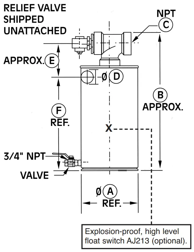
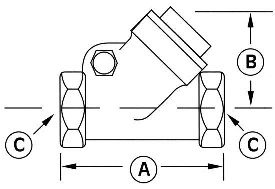
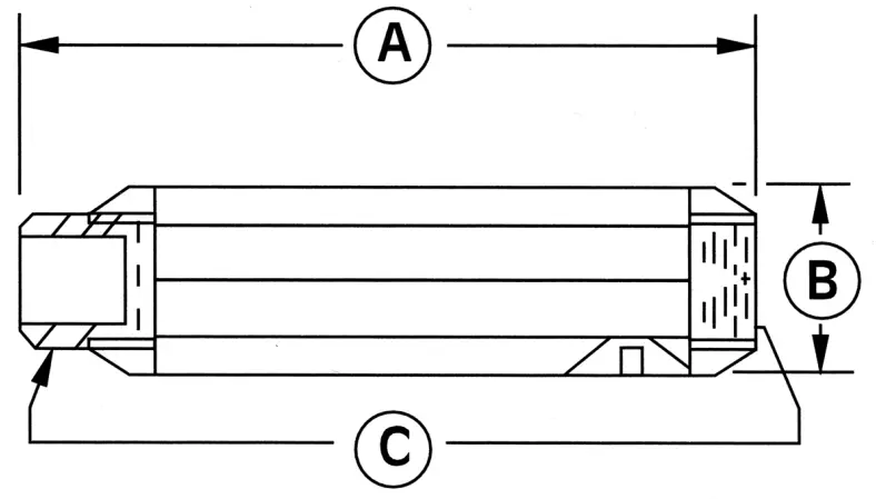
HORIZONTAL SWING TYPE CHECK VALVE
This check valve prevents backwash of fluids from entering the blower and air back-streaming.
The check valve can be mounted to discharge or inlet either vertically or horizontally. The check valve will open with 3” of water pressure or vacuum.
Model Number | R1, R2 | R3 | R4, R5, SDR4, SDR4, R4P | R6, R6P, SDR6P, SDR6, R6PS | R7, R7S |
| Part Number | AH326B | AH326C | AH326D | AH326F | AH326G |
Dimension (A) | 3.57” | 4.19” | 4.50” | 5.25” | 8.00” |
| Dimension (B) | 2.32” | 2.69” | 2.94” | 3.82” | 5.07” |
Dimension (C) | 1.00” NPT | 1.25” NPT | 1.50” NPT | 2.00” NPT | 2.50” NPT |
RECOMMENDED ACCESSORIES
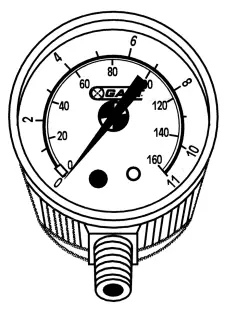 PRESSURE – VACUUM GAUGE
| Pressure/Vacuum Gauges | ||||
| AJ496 | 2.50” Dia. | Pressure | 1/4” NPT | 0-60 in. H2O and 0-150 mbar |
| AE133 | 2.50” Dia. | Pressure | 1/4” NPT | 0-160 in. H2O and 0-400 mbar |
| AE133A | 2.50” Dia. | Pressure | 1/4” NPT | 0-200 in. H2O |
| AJ497 | 2.50” Dia. | Vacuum | 1/4” NPT | 0-60 in. H2O and 0-150 mbar |
| AE134 | 2.50” Dia. | Vacuum | 1/4” NPT | 0-160 in. H2O and 0-400 mbar |
| AE134F | 3.50” Dia. | Vacuum | 1/4” NPT | 0-15 in. HG |
 PRESSURE – VACUUM RELIEF VALVE
| Pressure/Vacuum Relief Valves | ||
| AG258 | 1.50” NPT | Adjustable 30-200 in. H2O; 200 cfm max |
| AJ121D | Silencer for AG258 Relief Valve | |
| AG258F | 2.50” NPT | Adjustable 25-200 in. H2O; 560 cfm max |
| AJ121G | Silencer for AG258F Relief Valve | |
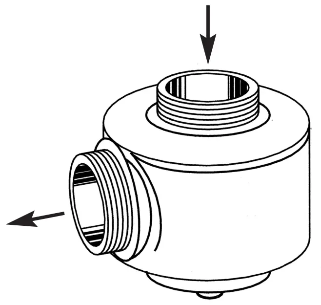
INLINE FILTERS (FOR VACUUM)
The impeller of a blower passes very closely to the housing. It is recommended to have an inlet or in-line filter to ensure a trouble-free service life.
MPT = Male Pipe Thread
FPT = Female Pipe Thread
Model Number | R1 | R2 | R3 | R4 | SDR4, R4P, R4H, R5 | SDR5, SDR6, R6, R6P, R7M | R6PP, SDR6P, R6PS, R7, R7S | R7S, R9, R9P, R9S |
| Part Number | AJ151A | AJ151B | AJ151C | AJ151D | AJ151E | AJ151G | AJ151H | AJ151M |
Dimension (A) | 5.88” | 7.38” | 7.38” | 7.38 | 8.75 | 8.75” | 14.00” | 18.50” |
| Dimension (A1) | – | – | – | – | – | – | 16.25” | 20.75” |
Dimension (B) | 4.50” | 6.81” | 6.81” | 6.81” | 10.25” | 10.50” | 27.13” | 28.13” |
| Dimension (C) | 2.75” | 4.62” | 4.62” | 4.62” | 5.00” | 5.50” | 18.50” | 19.50” |
Dimension (D) | 1.00” FPT | 1.00” FPT | 1.25” FPT | 1.50” FPT | 2.00” FPT | 2.50” FPT | 3”MPT | 5” MPT |
| Dimension (E) | 1.00” FPT | 1.00” FPT | 1.25” FPT | 1.50” FPT | 2.00” FPT | 2.50” FPT | 3”MPT | 5” MPT |
Replacement Element | AJ135D | AJ135E | AJ135E | AJ135E | AJ135F | AJ135G | AJ135C | AJ135H |
| Micron | 10 | 10 | 10 | 10 | 10 | 10 | 10 | 10 |
INLET FILTERS (FOR PRESSURE)
All filters are heavy duty for high-particulate service. Inlet filters for
Regenair blowers are drip-proof when mounted as shown..
MPT = Male Pipe Thread
FPT = Female Pipe Thread
Model Number | R1, R2 | R3 | R4, R4H, R4P SDR4, R5 | SDR5, R6, SDR6, R5P, R6PP, R6PS | SDR6P, R7, R7P, R7S | R9, R9P, R9S |
| Part Number | AJ126B | AJ126C | AJ126D | AJ126F | AJ126G | AJ126M |
Dimension (A) | 6.00” | 6.00” | 7.70” | 10.62” | 10.00” | 16.00” |
| Dimension (B) | 4.62” | 7.12” | 7.12” | 4.81” | 13.12” | 14.62” |
Dimension (C) | 1.00” MPT | 1.25” MPT | 1.50” MPT | 2.00” FPT | 2.50” MPT | 5” MPT |
| Replacement Element | AJ134B | AJ134C | AJ134E | AG340 | AJ135A | AJ135H |
Micron | 10 | 10 | 10 | 10 | 10 | 10 |
MUFFLERS
Designed to reduce noise by up to 5 dbA and remove high-frequency sound associated with all blowers.
Model Number | R1, R2 | R3 | R4, SDR4, R4P, R5 | R4H, R6, R6P, R6PS SDR6P, SDR6 | R7, R7S | R6PP, R9 Exhaust | R7P Exhaust |
| Part Number | AJ121B | AJ121C | AJ121D | AJ121F | AJ121G | AJ121H | AJ121M |
Dimension (A) | 7.46” | 7.94” | 12.75” | 17.05” | 17.44” | 20.30” | 33.60” |
| Dimension (B) | 2.38” | 2.62” | 3.25” | 3.63” | 4.25” | 4.75” | 6.00” |
Dimension (C) | 1.00” NPT | 1.25” NPT | 1.50” NPT | 2.00” NPT | 2.50” NPT | 3” NPT | 4”NPT |
PARTS & ORDERING INFORMATION
Please reference the exploded view on Page 11 for the following model and parts table.
REF# | ITEM | QTY | R1102 R1102C R1102K | R2103 R2303A | R2105 | R2305B | R3105-1 R3305A-1 R3305B-1 |
1 | COVER | 1 | AJ101A | AJ101B | AJ101B | AJ101B | AJ101C |
| 2 | LOCK NUT | 1 | BC187 | BC187 | BC181 | BC181 | BC181 |
3 | IMPELLER | 1 | AJ102A | AJ102BQ | AJ102B | AJ102B | AJ102C |
| 4 | SQUARE KEY | 1 | AH212C | AH212 | AB136A | AB136A | AB136A |
5 | SHIM SPACER | ∆ | AE686-5 | AE686-3 | AJ109 | AE686-3 | AJ109 |
| 6 | RETAINING RING | 1 | AJ145 | AJ145 | AJ149 | AJ145 | AJ149 |
7 | HOUSING | 1 | AJ103A | AJ103BQ | AJ103B | AJ103B | AJ103C |
| 8 | – | – | – | – | – | – | – |
9 | – | – | – | – | – | – | – |
| 10A | FOAM | ∆ | AJ112A(4) | AJ112BQ(6) | AJ112BQ(6) | AJ112BQ(6) | AJ112C(4) |
10B | FOAM | 2 | – | – | – | – | AJ112CQ |
| 11 | MUFFLER EXTENSION | 1 | AJ106A | AJ106BQ | AJ106BQ | AJ106BQ | AJ106CQ |
∆ As required.
Parts listed are for stock models. For specific OEM models, please consult the factory.
When corresponding or ordering parts, please give complete model and serial numbers.
Please reference the exploded view on the next page for the following model and parts tables.
REF# | ITEM | QTY | R3105-12 R3305A-13 | R4110-2 R4310A-2 R4310B-1 | R4P115 R4P315A† | R5125-2 R5325A-2 R5325B-1 | R6125-2 R6150J-2 R6325A-2 R6335A-2 R6335B R6350A-2 R6350B-2 | R6P335A R6P350A R6P350B | R6135J-10 |
1 | COVER | 1 | AJ101C | AJ101D | AJ101L | AJ101EQ | AJ101FB | AJ101K | AJ101FB |
| 2 | LOCK NUT | 1 | BC181 | BC181 | BC181 | AJ259 | AJ259 | AJ259 | AJ259 |
3 | IMPELLER | 1 | AJ102CA | AJ102D | AJ102L | AJ102E | AJ102FR | AJ102K | AJ102FR |
| 4 | SQUARE KEY | 1 | AB136A | AB136D | AB136D | AB136 | AB136 | AB136 | AB136 |
5 | SHIM SPACER | ∆ | AJ109 | AJ109 | AJ109 | AJ109 | AJ109 | AJ109 | AJ260A |
| 5 † | SHIM SPACER† | 1 | – | – | AJ109A† | – | – | – | – |
6 | RETAINING RING | 1 | AJ149 | AJ149 | AJ149 | – | – | – | – |
| 7 | HOUSING | 1 | AJ103C | AJ103DR | AJ103L | AJ103EQ | AJ103FQ | AJ103K | AJ103FQ |
8 | MUFFLER BOX | 1 | – | – | – | – | – | AJ104K | – |
| 9 | SPRING | 2 | – | AJ113DR | AJ113DQ | AJ113DQ | AJ113FQ | AJ113FQ | AJ113FQ |
9A | SCREEN | 2 | – | – | AJ123EQ | AJ123EQ | AJ123FB | – | AJ123FB |
| 10A | FOAM | ∆ | AJ112C(4) | AJ112DS(4) | AJ112ER(6) | AJ112ER(6) | AJ112FC(6) | AJ112K(8) | AJ112FC(6) |
10B | FOAM | 2 | AJ112CQ | AJ112DR | – | – | – | – | – |
| 11 | MUFFLER EXTENSION | 1 | AJ106CQ | AJ106DQ | AJ106EQ | AJ106EQ | AJ106FR | – | AJ106FR |
REF# | ITEM | QTY | R6P350A | R6P350B | R6P355A | R6PP3110M* | R6PS3110M* | R7100A-3 | R7100B-1 |
| 1 | COVER | 1 | AJ101K | AJ101K | AJ101KA | AJ101KA(2) | AJ101KA(2) | AJ101G | AJ101G |
2 | LOCK NUT/BOLT | 1 | AJ259 | AJ259 | BB750 | BB750(2) | BB750(2) | BB750 | BB750 |
| 3 | IMPELLER | 1 | AJ102K | AJ102K | AJ102KA | AJ102KA(2) | AJ102KA(2) | AJ102GZ | AJ102GA |
4 | SQUARE KEY | 1 | AB136 | AB136 | AB136 | AB136(2) | AB136(2) | AC628 | AC628 |
| 5 | SHIM SPACER | ∆ | AJ109 | AJ169F | AJ169F | AJ169F | AJ169F | AJ110 | AJ110 |
6 | RETAINING RING | 1 | – | – | – | – | – | – | – |
| 7 | HOUSING | 1 | AJ103K | AJ103K | AJ103KA | AJ103KD(2) | AJ103KD(2) | AJ103GA | AJ103GA |
8 | MUFFLER BOX | 1 | AJ104K | AJ104K | AJ104K | – | – | AJ104GA | AJ104GA |
| 8A | SCREEN | 2 | – | – | – | – | – | AJ998G | AJ998G |
9 | SPRING | 2 | AJ113FQ | AJ113FQ | AJ113FQ | – | – | – | – |
| 10A | FOAM | ∆ | AJ112K(8) | AJ112K (8) | AJ112K (8) | – | – | AJ112GA(8) | AJ112GA(8) |
10B | FOAM | 2 | – | – | – | – | – | – | – |
| 11 | MUFFLER EXTENSION | 1 | – | – | – | – | – | – | – |
12 ** | O-RING | 2 | – | – | – | AJ175 | – | – | |
| 13 | GASKET | 4 | – | – | – | AJ107F | AJ107F | – | – |
REF# | ITEM | QTY | R7P3180M* | R7S3180M* | R9P3300M* | R9S3300M* | R93150A |
| 1 | COVER | 1 | AJ101G(2) | AJ101G(2) | AJ101M(2) | AJ101M(2) | AJ101M |
2 | LOCK NUT/BOLT | 1 | BB750(2) | BB750(2) | BB707(2) | BB707(2) | BB707 |
| 3 | IMPELLER | 1 | AJ102GZ(2) | AJ102GZ(2) | AJ102M(2) | AJ102M(2) | AJ102M |
4 | SQUARE KEY | 1 | AC628(2) | AC628(2) | AE130A(2) | AE130A(2) | AE130A |
| 5 | SHIM SPACER | ∆ | AJ110 | AJ110 | BJ110 | BJ110 | BJ110A |
6 | RETAINING RING | 1 | – | – | – | – | – |
| 7 | HOUSING | 1 | AJ103GA(2) | AJ103GA(2) | AJ103M(2) | AJ103M(2) | AJ103M |
8 | MUFFLER BOX | 1 | – | – | – | – | AJ104MP |
| 8A | SCREEN | 2 | – | – | – | – | AJ998M |
9 | SPRING | 2 | – | – | – | – | – |
| 10A | FOAM | ∆ | – | – | – | – | AJ112M(10) |
10B | FOAM | 2 | – | – | – | – | – |
| 11 | MUFFLER EXTENSION | 1 | – | – | – | – | – |
12 ** | O-RING | 2 | AJ175G | – | AJ175G | – | – |
† R4P315A only.
* Dual models.
** Not shown.
∆ As required.
Parts listed are for stock models. For specific OEM models, please consult the factory. 10 When corresponding or ordering parts, please give complete model and serial numbers.
EXPLODED PRODUCT VIEW
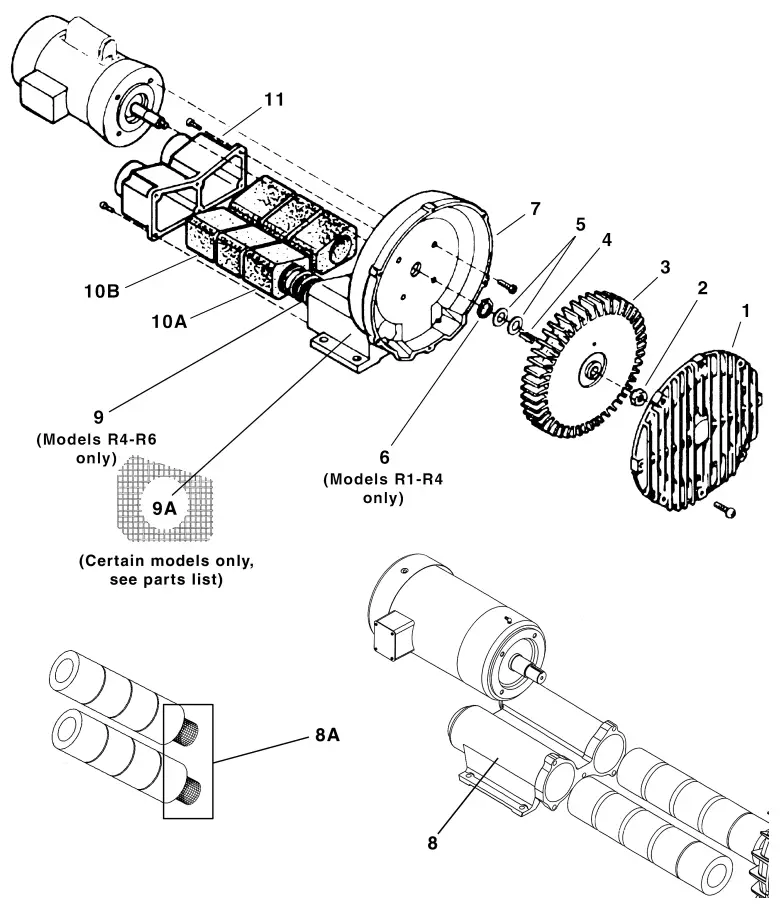
PART NO. 70 – 6000 F2-200 (REV-L)
TROUBLESHOOTING CHART
| Problem | Reason | Remedy |
| Increased sound. | Noise absorbing foam is damaged. Impeller rubbing inside. | Replace foam. Send unit to a Gast Authorized Service Facility. |
| Excessive vibration. | Damaged impeller. Motor and/or impeller are dirty. | Replace impeller. Clean motor and impeller periodically. |
| Ambient and exhaust temperature increases. | Motor and/or blower are dirty. Filters dirty. | Clean motor and blower periodically. Replace filters. |
| Decreased inlet air pressure | Inlet air filter is clogged. | Clean inlet filter. Replace cartridge. |
| Unit is very hot. | Wrong wiring. Low voltage. Inlet air filter is clogged. Motor and/or blower are dirty. Operating at too high a pressure or vacuum. | Check wiring. Supply proper voltage. Clean inlet filter. Replace cartridge. Clean motor and blower periodically. Install a relief valve and pressure or vacuum gauge. |
| Unusual sound. | Impeller is damaged or dirty. Bearing going bad. | Clean or replace impeller. Send unit to a Gast Authorized Service Facility. |
| Motor overload | Low voltage. | Check power source. Check wire size and wire connections. |
| Unit does not start. | Incorrect electrical connection or power source. Impeller is damaged. | Check wiring diagram, circuit fusing and circuit capacity. Clean or replace impeller. Install proper filtration. |
We have Gast Certified Service Centers throughout the world. For the most up todate listing, contact one of our sales offices below:
Gast Manufacturing, Inc.
P.O. Box 97
2300 S. Highway M139
Benton Harbor, MI 49023-0097
Ph: 269/926-6171
FAX: 269/925-8288
www.gastmfg.com
Gast Hong Kong
Room 6,9/F
New Commerce Centre
19 on Sum Street, Shatin
N. T. Hong Kong
Ph: (852) 2690 1066
Fax: (852) 2690 1012
www.gasthk.com
Gast Group Limited, United Kingdom
Unit 11, The I O Centre
Nash Road
Redditch, B98 7AS
United Kingdom
ph: +44 (0) 1527 504040
Fax: +44 (0) 1527 525262
www.gastmfg.com