![]() FXLS8471Q HANI IoT Board
FXLS8471Q HANI IoT Board
User Guide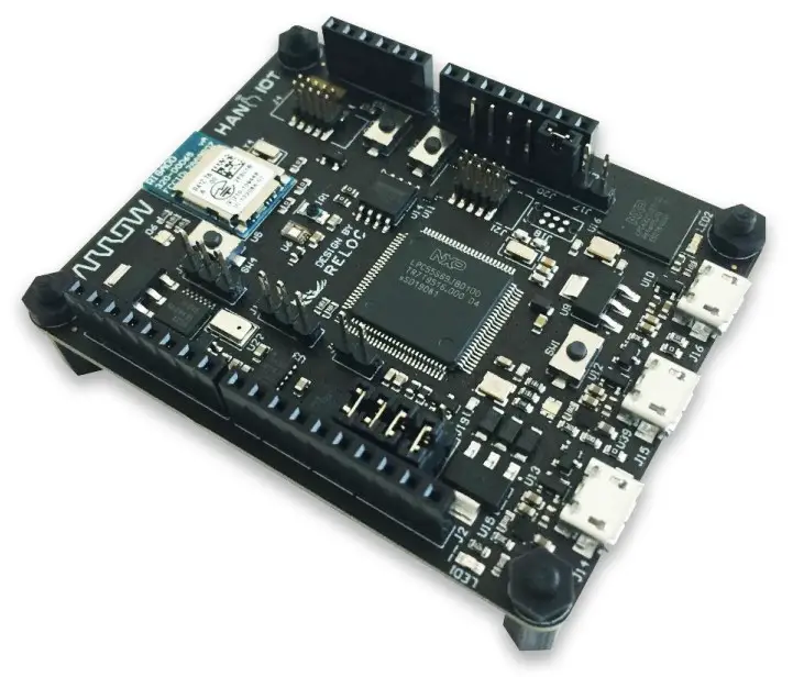
All information contained in these materials, including products and product specifications, represents information on the product at the time of publication and is subject to change by RELOC s.r.l. without notice.
Revisions
| REVISION | DATE | DESCRIPTION | STATUS | AUTHOR | REVISER |
| 0.5 | 31/05/2019 | Preliminary internal release | draft | L. Dal Bello | |
| 0.7 | 18/06/2019 | Updated pictures, project creation and description of connectors | draft | L. Dal Bello |
Disclaimer
All rights are strictly reserved. Reproduction in any form is not permitted without written authorization from RELOC s.r.l.
All information contained in these materials, including products and product specifications, represents information on the product at the time of publication and is subject to change by RELOC s.r.l. without notice.
| RELOC s.r.l. | Phone +39 0521 649116 |
| Strada Langhirano, 264/3A | www.reloc.it |
| 43124 – Parma (Italy) | [email protected] |
Introduction
1.1. Description
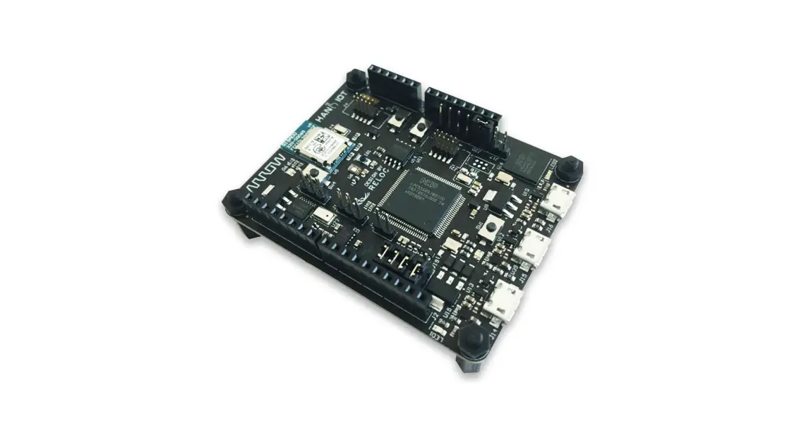
HANI IoT board, developed by RELOC for Arrow Electronics, is a ready-to-use Internet of Things (IoT) hardware and software platform that enables users to get their IoT applications up and running quickly.
Based on NXP LPC55S69 dual-core Cortex-M33 MCU, the board provides an extensive set of environmental sensors (temperature, pressure, light, accelerometer, gyroscope) that can be used as building blocks for the IoT application.
A secure memory, USB connectors, and wireless BLE interface provide additional functions for a robust IoT kit.
1.2. Kit contents
The following items are included in the box:
- 1x HANI IoT board
- 4x standoff spacers for the board
System overview
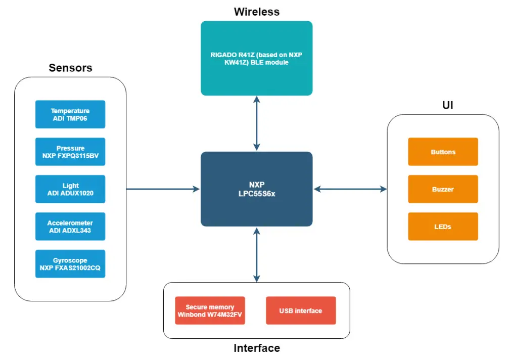
2.1. Block diagram
An overview of the functional blocks of HANI IoT board is shown in the figure below.
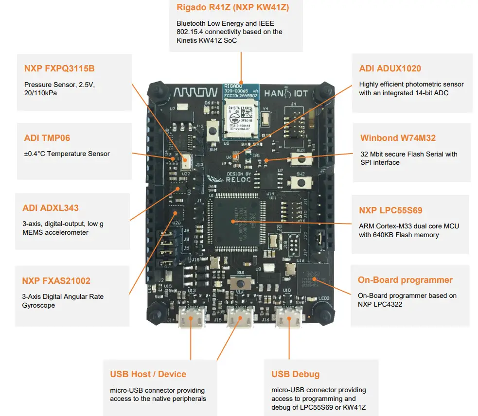
2.2. Main devices
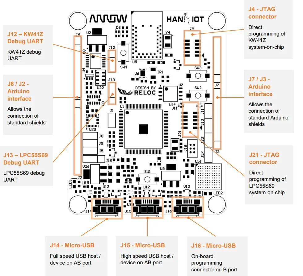
HANI IoT board’s main features are summarized in the picture below.
Getting started
3.1. HANI IoT pre-programmed demo
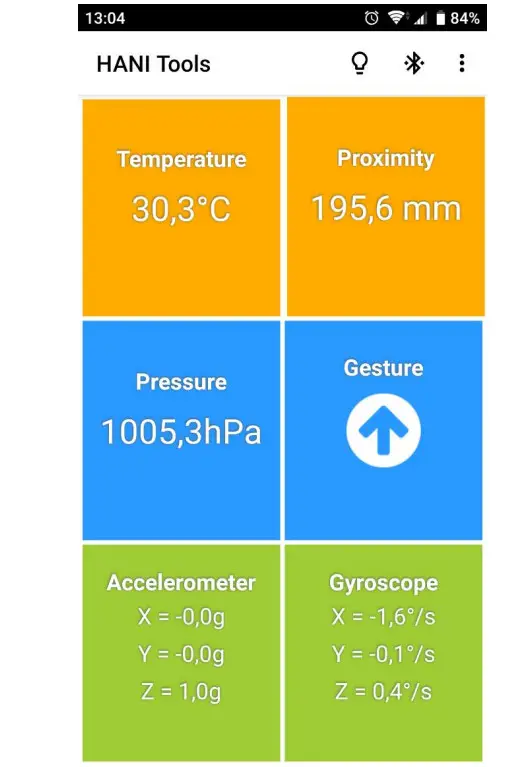
The HANI IoT board is pre-programmed with a demo application that continuously monitors the onboard sensors and sends collected data on Bluetooth Low-Energy (BLE) network.
The LPC55S69 device takes care of sampling sensors data whereas the KW41Z multi-protocol module establishes the BLE communication with a BLE client.
In order to test HANI IoT functionalities by means of the pre-programmed demo application
- download the free HANI IoT smartphone App from Google PlayTM
- power supply the board through one of the USB connectors
- open the ARIS Tools smartphone App and select your HANI from the device list.
The application:
a. shows sensor values in real-time through the BLE communication channel,
b. enables users to remotely control the board LEDs by means of App buttons.
3.2. Creating and debugging a sample “Blinky” project
3.2.1 Prerequisites
The following development tools should be installed before trying to either create a project or use an example based on the HANI IoT board:
- MCUXpresso Integrated Development Environment (IDE) v10.3.1 or later release http://www.nxp.com/mcuxpresso/ide
- MCUXpresso SDK for LPC55S69 v2.5.1 or later release You can build it by yourself starting from this page: https://mcuxpresso.nxp.com/en/welcome
“Select Development Board” and choose processor LPC55S69, then “Build MCUXpresso SDK” and “Download SDK”. - MCUXpresso SDK for MKW41Z512xxx4 v2.2.0 or later release (optional, for KW41Z development) https://mcuxpresso.nxp.com/en/welcome
“Select Development Board” and choose processor MKW41Z512xxx4, then “Build MCUXpresso SDK” and “Download SDK”.
SDKs should be installed from within MCUXpresso, please refer to the official documentation.
Please refer to the NXP website ( www.nxp.com) if previous links are outdated.
3.2.2 Board configuration and connection
Connect the HANI IoT board to your PC through the micro-USB port J16: this connection provides the board with a power supply and represents the interface for project flashing and debugging via an onboard programmer.
Please refer to the following chapters for additional information about the board power supply distribution.
According to the jumper J20, the onboard debugger is connected to the LPC55S69 MCU if the jumper is a shunt, or to the KW41Z if the jumper is open.
In the following chapters, the creation, building, flashing, and debugging of a project for LPC55S69 MCU will be used as an example; to ensure that J20 jumper is a shunt.
3.2.3 Creating and building a demo project
To create a new project with HANI board as a target, please follow these steps within MCUXpresso:
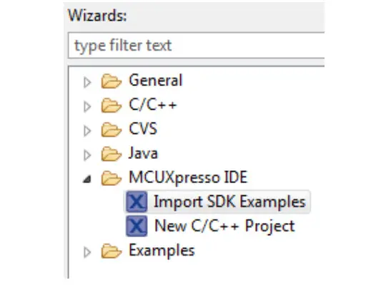
- Select: File → New → Project in the menu and then select: MCUXpresso IDE -> Import SDK Examples

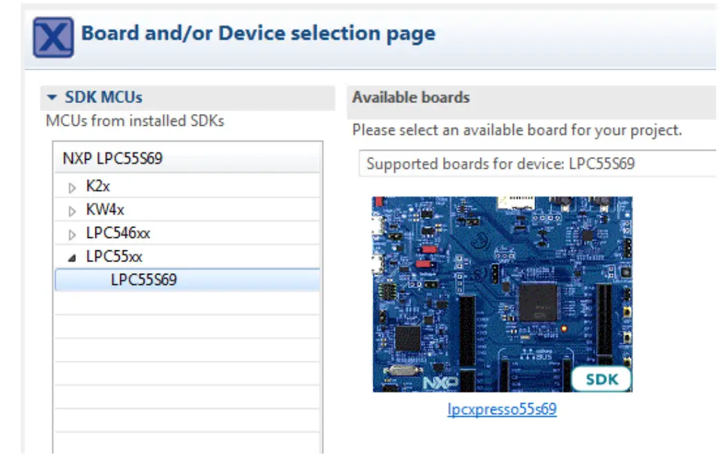
- Select: lpcxpresso55s69 board on the right panel and press Next to continue:

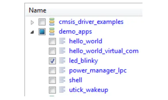
- Assign a project name and select an example (e.g. led_blinky) as a starting point:

- Press the “Finish” button to confirm the selection
Then you should change the source code, as required by the example and by your target application; for the led_blinky example:
- Open source → source/led_blinky.c
- Modify existing Definitions:
/***********************************************************
* Definitions
*********************************************
#define BOARD_LED_PORT BOARD_LED_BLUE_GPIO_PORT
#define BOARD_LED_PIN BOARD_LED_BLUE_GPIO_PIN
With proper definitions for current board:
/*****************************************************************
* Definitions
************************************************************/
#define BOARD_LED_PORT 1U
#define BOARD_LED_PIN 17U
- You should now be able to build the project by clicking on the Build button:
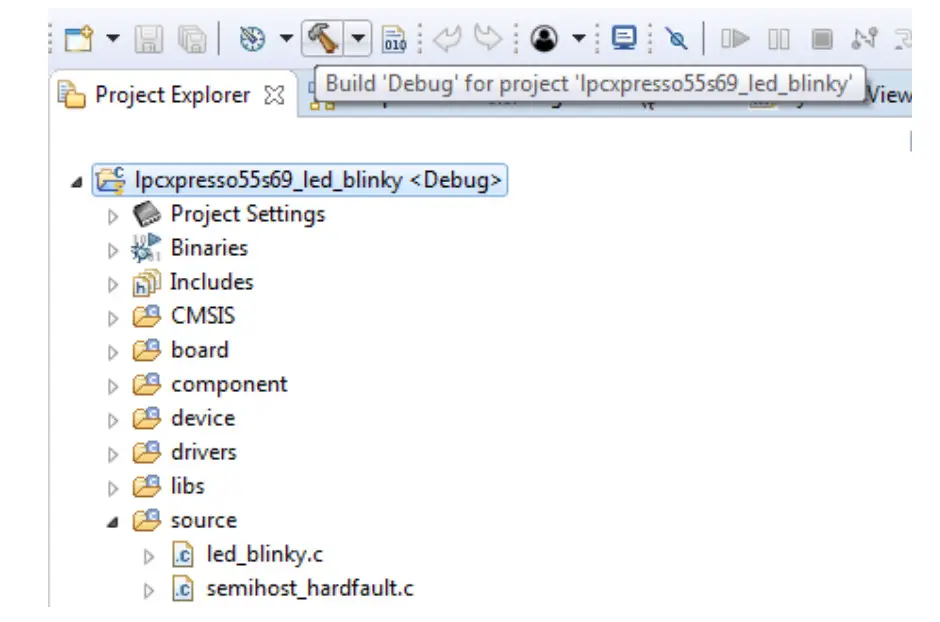
Compilation should end without any errors.
3.2.4 Program and debug the project
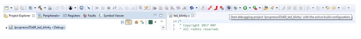
In order to check the correct behavior of the sample application starts the Debug by selecting this icon in the menu:
Select the appropriate debug interface if required, then click the Resume button (F8) to start the execution: 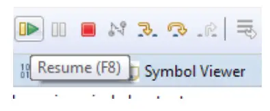
The led managed by the MCU should start blinking with green color.
Connectors
This chapter gives an overview of HANI IoT connector’s placement and their functionalities.
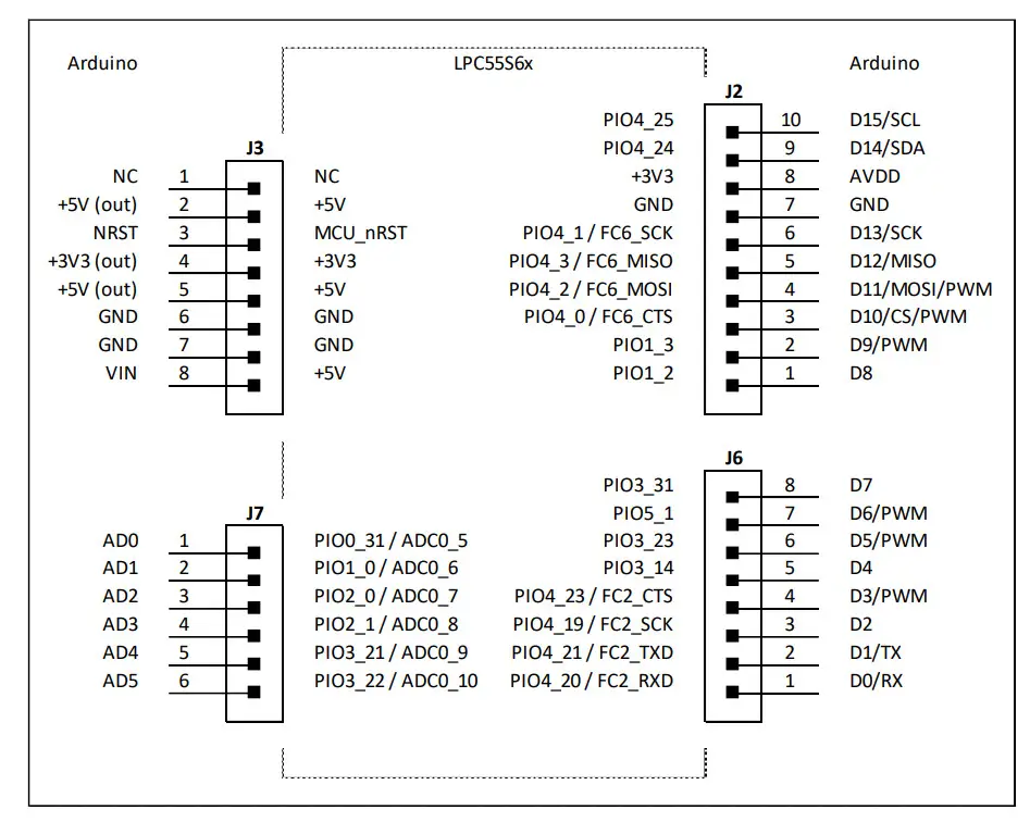
4.1. Arduino expansion connector
Connectors J2, J3, J6 and J7 provide user with a standard Arduino shield expansion slot.
4.2. JTAG connectors
The HANI IoT development kit features an on-board debugger (see J16 micro-USB port), which can be used to program and debug both LPC55S69 and KW41Z devices.
The board includes additional JTAG connectors, detailed below for reference:
- J21 – JTAG connector which can be used to program and debug LPC55S69 with an external J-Link debugger;
- J4 – JTAG connector routed to the Rigado R41Z module.
4.3. User interface
HANI developer is provided with a basic user interface, including buttons and LEDs directly connected to NXP LPC55S6x MCU and other devices.
Mapping between port numbers and the physical designator is provided below.
| Device | Port | Schematic Signal | Description |
| System | +3V3 | LED1 Green LED | |
| NXP LPC55S6x | RESET | RESETN | SW2 tactile switch connected to MCU reset signal (active low) |
| P101 1 | Ul SWI | SW1 tactile switch | |
| P101_4 | Ul LEDR | D5 LED Red component | |
| P101_17 | Ul LEDG | D5 LED Green component | |
| PI01_18 | UI_LEDB | D5 LED Blue component | |
| PI01_19 | Ul_BUZ | BZ1 Buzzer control | |
| Rigado R41Z | PTA2 | RF nRST | SW3 tactile switch connected to MCU reset signal (active low) |
| PTCS | RF_BUT | SW4 tactile switch | |
| PTC1 | RF_LED_RED | D6 LED Red component | |
| PTC2 | RF_LED_GREEN | D6 LED Green component | |
| PTC3 | RF_LED_BLUE | D6 LED Blue component | |
| NXP LPC4322 | P1[1] | LED2 Yellow LED |
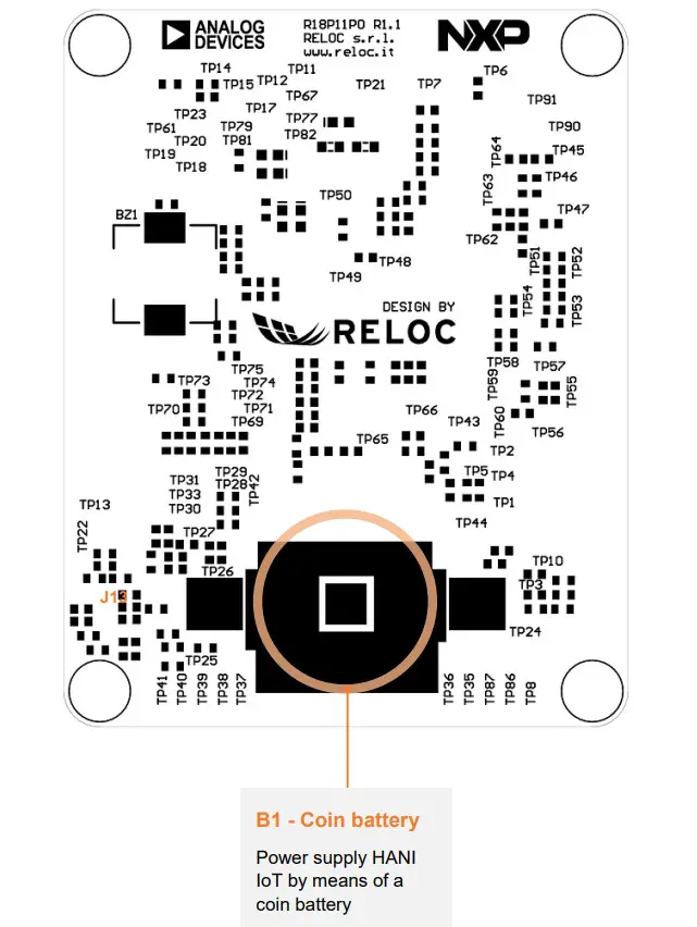
Board layout
Top and bottom board layouts (component placement and overlay) are provided for reference purposes. 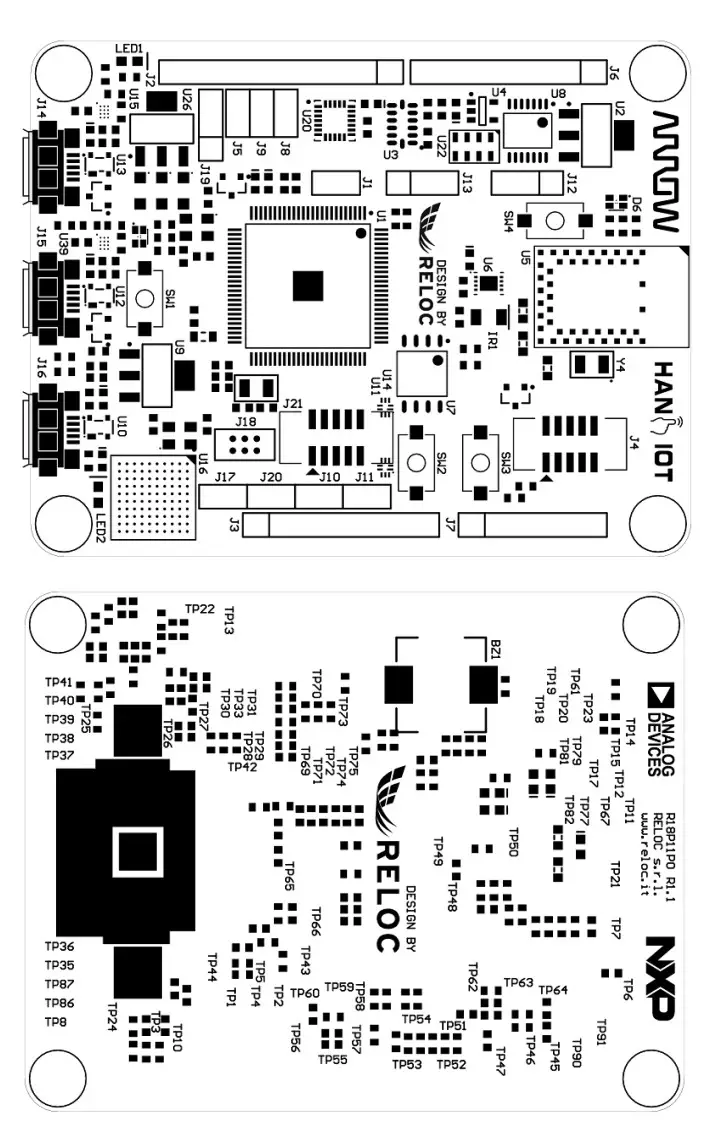
References
 NXP® Semiconductors Official Site | NXP Semiconductors
-
MCUXpresso IDE for NXP MCUs | Linux, Windows and MacOS | NXP Semiconductors | NXP Semiconductors
-
RELOC | Join the Internet of Things revolution. Today.Homepage - RELOC | Join the Internet of Things revolution. Today.
-
Welcome | MCUXpresso SDK Builder


