![]() PORTABLE POWER
PORTABLE POWER
REPAIR BODY KIT
Instruction Manual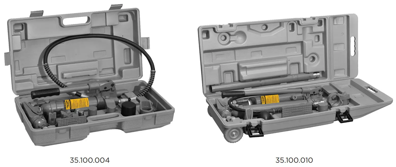
35.100.004 Portable Power Repair Body Kit
OPERATING INSTRUCTIONS MANUAL
| MODEL NO. | CAPACITY |
| 35.100.004 | 4 TON |
| 35.100.010 | 10 TON |
SAFETY & WARNING INFORMATION
![]() This is the safety notification symbol.
This is the safety notification symbol.
This symbol will notify you of any potential injury hazards. Please follow all instructions that follow this symbol to avoid possible injuries or death.![]() WARNING
WARNING
Indicates a hazardous situation. If proper steps are not followed, death or serious injury could result.![]() IMPORTANT: READ ALL INSTRUCTIONS BEFORE USE
IMPORTANT: READ ALL INSTRUCTIONS BEFORE USE
Before using the Portable Power Body Repair Kit, be sure to read all content within this manual, ensuring that you understand the operating procedures, maintenance requirements, and all safety warnings.
The owner and/or operator shall have an understanding of the product, its operating characteristics, and safety operating instructions before operating this device. Safety information shall be emphasized and understood. If the operator is not fluent in English, the product and safety instructions shall be read to and discussed with the operator in the operator’s native language by the purchaser/owner or his designee, making sure that the operator comprehends their contents. This Portable Power Body Repair Kit meets or exceeds ASME/PASE 2014 standards.![]() WARNING
WARNING
ACTIONS TO HELP PREVENT DANGEROUS SITUATIONS
- Study, understand and follow all instructions before operating this device.
- Do not exceed the rated capacity stated.
- Use only on hard-level surfaces.
- Do not drop heavy objects onto the hose, and do not allow the hose to kink
- Always allow clearance for the hose to avoid damage to the hose and couplers
- Keep equipment away from heat or fire, as this may damage or weaken the equipment
- No alterations shall be made to this product.
- Failure to heed these markings may result in serious personal injury/property damage
SETUP, OPERATION & PREVENTIVE MAINTENANCE
![]() SETUP
SETUP
Prior to each use, a visual inspection shall be made to the device by checking for abnormal conditions, such as cracked welds, damaged, loose, or missing parts.![]() ASSEMBLY
ASSEMBLY
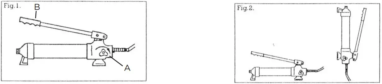
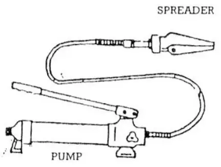
Connect the hydraulic ram and pump unit hose together, and ensure you have securely fastened the couplings before pumping.
Firmly close the release valve (A) by turning it in a clockwise direction. Fig 1.
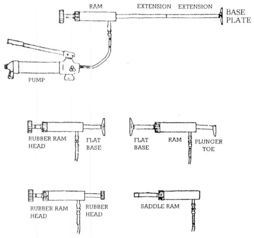
Attachment Combinations
The pump unit can be used with a multi-directional ram. This enables many attachment combinations.![]() LIFTING
LIFTING
Apply pressure to the pump (B) by pumping the handle up and down. Fig 1.![]() LOWERING
LOWERING
To release the pressure, turn the valve anti-clockwise.
Note:
The pump can be used in any position i.e. horizontal to vertical. Always keep the hose end of the pump unit facing downwards when positioned vertically. Fig. 2.
SUGGESTED SYSTEM ASSEMBLIES
MAINTENANCE
NOTICE:
Use high-grade hydraulic oil only. Never use brake fluid, motor oil, transmission fluid, turbine oil, or any other fluids.
ISO-VG22 or equivalent hydraulic oil is recommended.
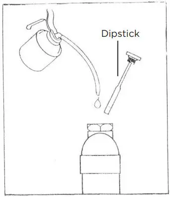
CHECK AND REFILL THE OIL
To check the oil level, place the pump unit in an upright position. As indicated on the diagram opposite. Remove the dipstick and the oil level will be indicated. If required add hydraulic oil until it is leveled with the full mark on the stem. As indicated in fig.3
Full replacement of oil is recommended every year for maximum life. To drain, remove the dipstick and open the release valve. Ensure that no dirt gets into the system. Refill with approved high-grade hydraulic oil.
LUBRICATION AND CLEANING
Periodically clean and lubricate all moving parts and pivot points. A periodic light coating of lubricant on all moving parts will help prevent the development of rust.
AIR VENTING PROCEDURES
Occasionally, air bubbles become trapped inside the equipment, reducing its efficiency. Bleed air out of the equipment’s hydraulic system as follows:
- Open the release valve, and remove the dipstick.
- Operate the pump rapidly several times to force air out. Some oil could splatter.
- Close the release valve, and replace the dipstick.
The equipment should now operate normally. If not, repeat the purging procedure as needed.
DAMAGED EQUIPMENT
Any equipment that appears to be damaged in any way, is found to be worn or operates abnormally SHALL BE REMOVED FROM SERVICE UNTIL REPAIRED. It is recommended that necessary repairs be made by a manufacturer or supplier’s authorized repair facility if repairs are permitted by the manufacturer or supplier.
ALTERATIONS
Because of potential hazards associated with this type of equipment, no alterations shall be made to the product.
ATTACHMENTS AND ADAPTERS
Only attachments and/or adapters supplied by the manufacturer shall be used.
INSPECTION, STORAGE & TROUBLESHOOTING
![]() INSPECTION
INSPECTION
Owners and/or operators should be aware that repair of this equipment may require specialized knowledge and facilities. It is recommended that an annual inspection of the product is made by a manufacturer or supplier’s authorized repair facility and that any defective parts, decals, or safety labels or signs be replaced with the manufacturer or supplier’s specified parts.
This device shall be inspected immediately if the device is believed to have been subjected to an abnormal load or shock. It is recommended that this inspection be made by a manufacturer or supplier’s authorized repair facility.![]() STORAGE
STORAGE
When the body repair kit is not in use, the pump unit should be stored with the release valve open in a dry location on a level surface![]() TROUBLESHOOTING
TROUBLESHOOTING
| SYMPTOM | POSSIBLE CAUSES | SOLUTION |
| JACK WILL NOT WORK | DIRT ON VALVE SEALS/ WORN SEALS | REPLACE WITH NEW SEALS |
| JACK WILL NOT PRODUCE PRESSURE | AIR BLOCK | 1)OPEN THE RELEASE VALVE AND REMOVE THE DIPSTICK 2)PUMP HANDLE A COUPLE OF FULL STROKES AND CLOSE RELEASE VALVE 3)REPLACE THE DIPSTICK |
| JACK UNIT FEELS UNSTEADY UNDER LOAD | ||
| JACK WILL NOT LOWER COMPLETELY | ||
| JACK WILL NOT PRODUCE PRESSURE | THE RESERVOIR COULD BE OVERFILLED OR LOW ON THE HYDRAULIC OIL LEVEL | TO CHECK THE OIL LEVEL. REMOVE THE DIPSTICK AND TOP UP OR DRAIN TO THE CORRECT LEVEL. |
| JACK UNIT FEELS UNSTEADY UNDER LOAD | THE PUMP SEAL COULD BE WORN OUT | REPLACE CUP SEAL WITH A NEW ONE |
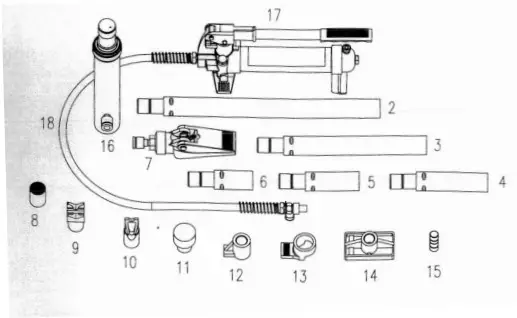
PARTS BREAKDOWN
| REF | DESCRIPTION | QTY |
| 2 | Extension bar 1 | 1 |
| 3 | Extension bar 2 | 1 |
| 4 | Extension bar 3 | 1 |
| 5 | Extension bar 4 | 1 |
| 6 | Extension bar 5 | 1 |
| 7 | Spreading wedge | 1 |
| 8 | Serrated cap | 1 |
| 9 | “V“ Base | 1 |
| 10 | Cleft cap | 1 |
| 11 | Rubber head | 1 |
| 12 | Plunger toe | 1 |
| 13 | Ram’s toe | 1 |
| 14 | Base plate | 1 |
| 15 | Male connector | 1 |
| 16 | Ram unit | 1 |
| 17 | 4-ton pump unit | 1 |
| 18 | Hydraulic hose | 1 |
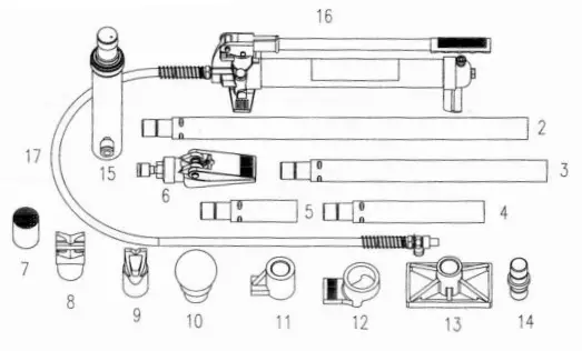
| REF | DESCRIPTION | QTY |
| 2 | Extension bar 1 | 1 |
| 3 | Extension bar 2 | 1 |
| 4 | Extension bar 3 | 1 |
| 5 | Extension bar 4 | 1 |
| 6 | Spreading wedge | 1 |
| 7 | Serrated cap | 1 |
| 8 | “V“ Base | 1 |
| 9 | Cleft cap | 1 |
| 10 | Rubber head | 1 |
| 11 | Plunger toe | 1 |
| 12 | Ram’s toe | 1 |
| 13 | Base plate | 1 |
| 14 | Male connector | 1 |
| 15 | Ram unit | 1 |
| 16 | 10-ton pump unit | 1 |
| 17 | Hydraulic hose | 1 |
WARRANTY INFORMATION
ONE-YEAR LIMITED WARRANTY
For a period of one (1) year from your purchase date, BE AG & INDUSTRIAL will repair or replace (at its option) without charge, your BE AG & INDUSTRIAL product if it was purchased new and the product has failed due to a defect in material or workmanship which you experienced during normal use of the product. This limited warranty is your exclusive remedy.
If this BE AG & INDUSTRIAL product is altered, abused, misused, modified, or undergoes service by an unauthorized technician, your warranty will be void. We are not responsible for damage to ornamental designs you place on this BE AG & INDUSTRIAL product and such ornamentation should not cover any warnings or instructions or they may void the warranty. This warranty does not cover scratches, superficial dents, and other abrasions to the paint finish that occur under normal use.
To access the benefits of this warranty, contact the dealer or retailer where the unit was purchased. For further assistance, you can contact BE AG & INDUSTRIAL at [email protected] for confirmation that this warranty applies. Thereafter, you may be advised to return the product under warranty, freight prepaid, to the dealer, or directly to the BE AG & INDUSTRIAL service department. Subject to the law in your province or state:
- Your sole and exclusive remedy is the repair or replacement of the defective product as described above.
- BE AG & INDUSTRIAL is not liable for any incidental damages, including but not limited to, lost profits and unforeseeable consequences.
- The repair and replacement of this product under the express limited warranty described above is your exclusive remedy and is provided in lieu of all other warranties, express or implied. All other warranties, including implied warranties and warranties of merchantability or fitness for a particular purpose, are disclaimed and, if the disclaimer is prohibited, these warranties are limited to one year from your date of purchase of this product.
![]() [email protected]
[email protected]
TOLL FREE PHONE / NUMÉRO DE TÉLÉPHONE SANS FRAIS: 1-877-588-3311


