Carrier R32 Air-to-water Monobloc Wired controller User Manual
Acronyms | |
| IDU | Indoor unit |
| ODU | Outdoor unit |
| DHW | Domestic hot water |
| EH | Electrical heater |
| IAT | Indoor ambient temperature |
| OAT | Outdoor ambient temperature |
| LWT | Leaving water temperature |
| EWT | Entering water temperature |
| Tw-in | Entering water temperature of BPHE |
| Tw-out | Leaving water temperature of BPHE |
| BPHE | Brazed Plate Heat Exchanger |
Presentation
This wired controller is used to control the operation of the unit and configuration of the system. It can also be used to check the system running parameter and display the status of system via the LCD screen. The wired controller communicates with the IDU (Indoor unit) board with certain protocols and detect the communication status in real time. The IDU board will activate the communication fault alarm once it loses communication. However, it will not send the alarm if you do not connect the wired controller to the IDU board with the system power on. Hence, if the wired controller is not necessary, please do not connect it before the system is powered on. The wired controller will shut down its screen for saving energy without needing to press for 35s (except the technical parameter configuration), and will wake up if you press any button.
Application of the wired controller:
- Power supply: Take power supply from IDU board (12V power supply);
- Working temperature range: -300 ~500
- Working humidity range: RH10%~95%
Wired controller can be installed inside your home or on the unit itself for split types. This manual provides guidelines on how to use this interface effectively. If you have any questions regarding the display and its configuration, please contact your installer for more information.
Caution:
- Do not press the button of wired controller for 5s after power on.
If you have any questions regarding the display and its configuration, please contact your installer for more information
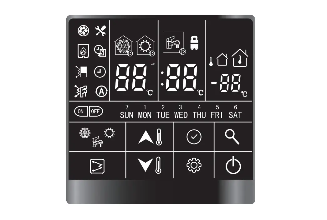
Interface introduction
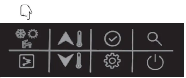
Button Overview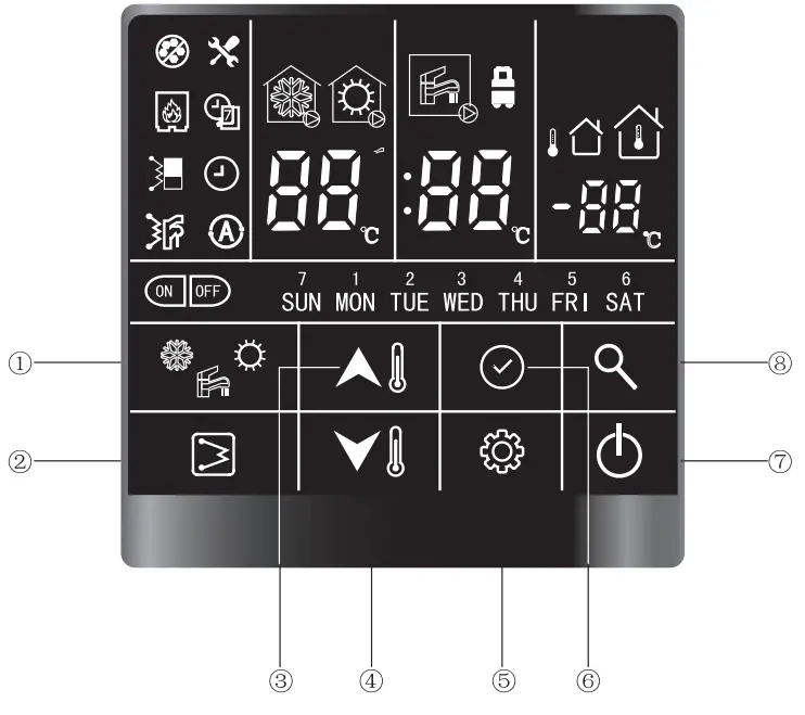
| Definition | Description |
| Used to change the running mode |
| Used to manually switch on/off the DHW EHs | |
| Used to change the value of the parameter or turn the page during system configuration or commissioning | |
| Used to change the value of the parameter or turn the page during system configuration or commissioning | |
| Used to set user / technical parameter configuration | |
| Used to confirm the current setting | |
| Used to turn on/off the unit | |
| Used to query the operation parameter or configuration parameter |
Overview of Icons
| |||||
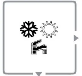
 | Non-operating cooling mode | Non-operating heating mode |  | Non-operating DHW mode | |
 | Operating cooling mode | Operating heating mode |  | Operating DHW mode | |
| Anti-frozen protection | Main water loop EHs |  | DHW EHs | ||
| External heat source (boiler) | Weekly timer |  | Clock | ||
| Timer on | Timer off |  | Alarm | ||
| Air purge mode | OTA (water setpoint control) |  | IAT (air setpoint control) | ||
| LWT/time display (hour)/alarm | | DHW temp./time display (minute) | 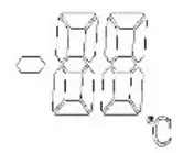 LED display (Right) | IAT/OAT(OAT is reserved) | |
| Days of week |  | Constant light: Eco modeFlash: Away mode | |||
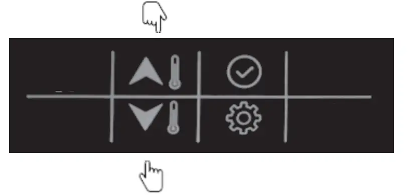
This wired controller has 8 buttons for the setpoint control, configuration, parameter check, etc. Details of each button are given in the table below:
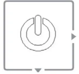 ON/OFF | 1. Press this button to turn the unit on and off. | |
 Confirm | 1. Press this button to confirm the setting to exit the interface of parameter setting or query. | |
 Mode | 1. Press this button to change the mode: cooling-heating-cooling.2. Press and hold this button to activate the anti-legionella mode manually. | |
Query | 1. Press this button to check the configuration and running parameters.2. Refer to section 3, parameter and status check, for details. | |
 EHs | 1. While operating in heating mode, press this button to activate/deactivate the main water loop EHs manually.2. While operating in DHW mode, press this button to activate/deactivate the DHW EHs manually.3. Press and hold this button to start force-defrosting, and the wired controller will display “dF” for 5s. | |
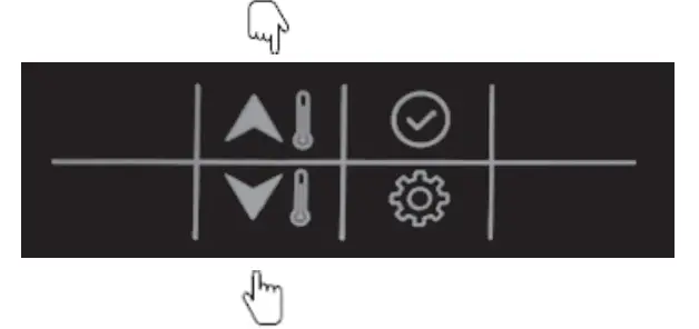
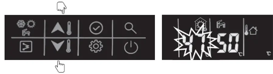
 Up Up | 1. Temperature setting① While in standby mode, for the first time, press this button to change the settingvalue of LWT; press the confirm button or wait for 5s without pressing any button for DHWtemperature setting.② While operating in cooling/heating mode, for the first time, press this button to change the setting value of LWT; press the confirm button or wait for 5s without pressing any button for DHW temperature setting.③ While operating DHW mode, for first time, press this button to change the setting temperature of DHW; press the confirm button or wait for 5s without pressing any button for setting the value of LWT.2. Time correction and timer setting① Refer to details for configuration. | |
Down | ||
 Setting | 1. User parameter configuration: please refer to the configuration section.2. Technical parameter configuration: please refer to the configuration section. | |
User operation
Clock setting
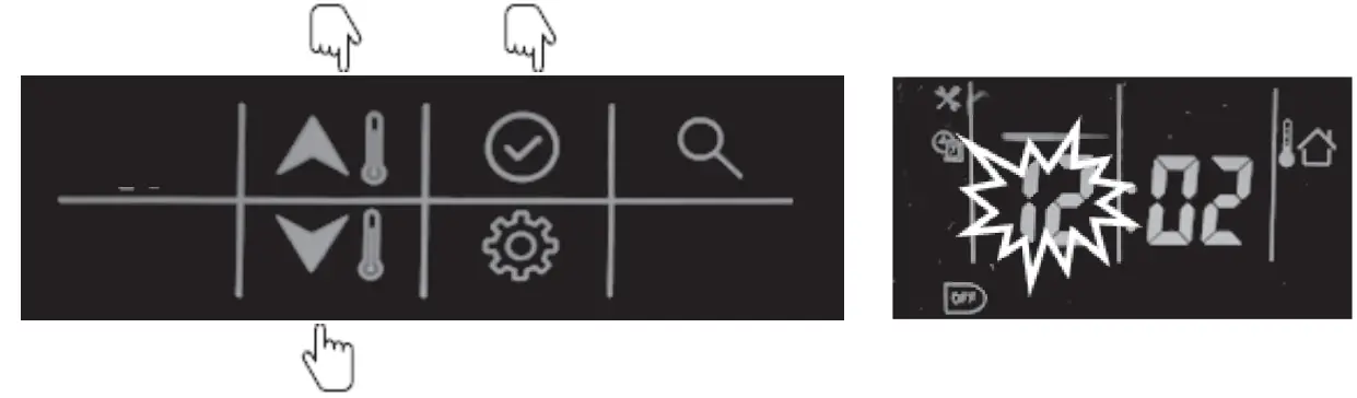
Before usage, it is necessary to set the time and date of the wired controller. Please follow the steps below to set the clock accurately:
- Press the “setting” button, then press “confirm” button to enter day settings; the date will flash at this moment.

- Next, press the “up” or “down” button to change the date, if necessar

- . After setting the date, press the “confirm” button to enter time settings. The hour will flash at this moment

- Next, press the “up” or “down” button to set the correct time in hours;

- After setting the hour, press the “confirm” button to enter the “minutes” setting; the minutes will flash at this moment.
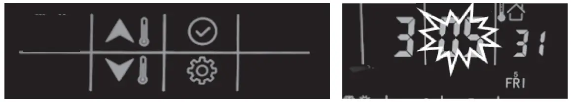
- Next, press the “up” or “down” button to set the correct time in minutes;

- Press the “confirm” button to confirm and exit clock settings. You can also press the “settings” button to go to the next parameter. (Refer to the user parameter configuration for the full details on parameters setting)
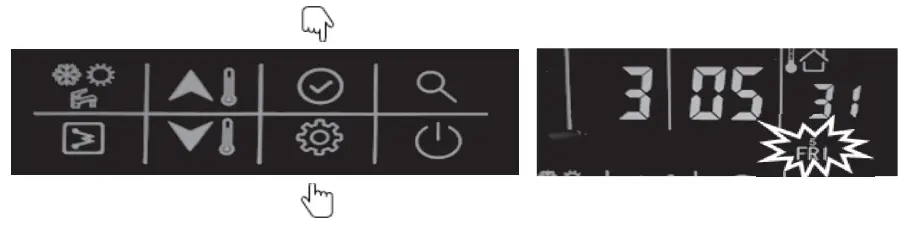
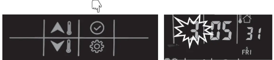
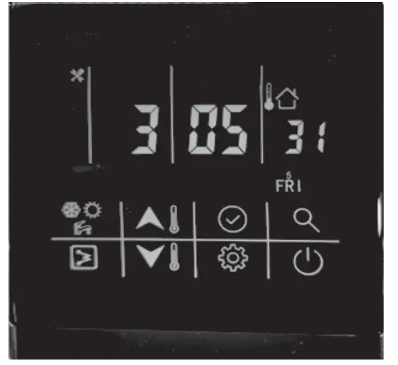
Example: Friday, 3:05:31
ON-OFF setting
Mode setting
1. Press this button to chang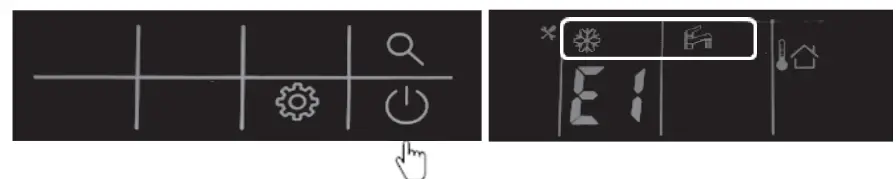
Mode setting
- Press this button to change the mode: cooling-heating-cooling.

Example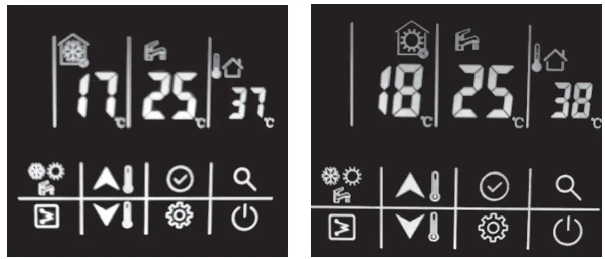
| Mode | Cooling | Mode | Heating |
| Occupancy | Home | Occupancy | Home |
| Temp. control | Water setpoint control | Temp. control | Water setpoint control |
| Setpoint of LWT | 170C | Setpoint of LWT | 180C |
| Setpoint of DHW | 250C | 250C |
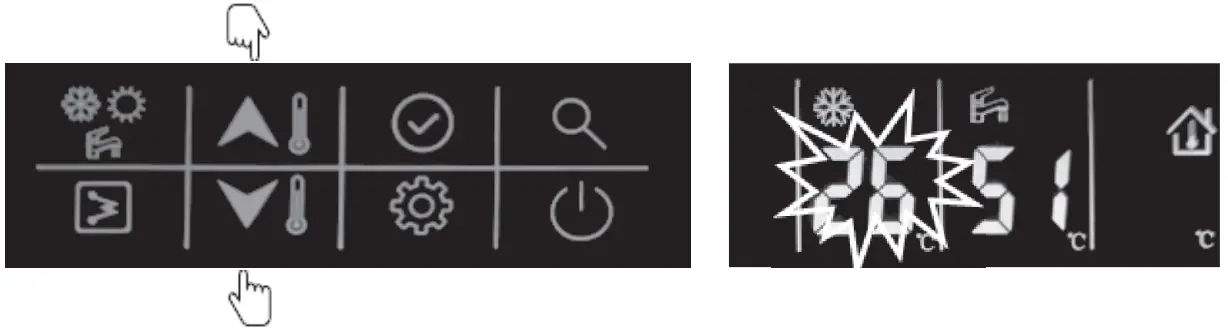
Current setpoint setting
Here are two setpoint controls: (Refer to the technical parameter configuration, item 1 for detailed settings)
- Water setpoint control; the unit is controlled by water setpoint;
- Air setpoint control: the unit is controlled by the air setpoint, and it requests to install the wired controller in the room.
There is an IAT sensor built inside the wired controller to detect the room temperature. Here are the steps to change the water setpoint control:
- While in standby mode or operating cooling/heating mode: First press “up” or “down” button to change the setting of LWT;
Then press the confirm button or wait for 5s without pressing any button to DHW temperature setting. Next, press the “up” or “down” button to change the setting of DHW.
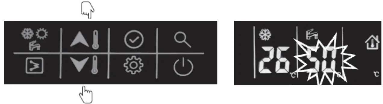
- While operating in DHW mode:
First press the “up” or “down” button to change the temperature of DHW;
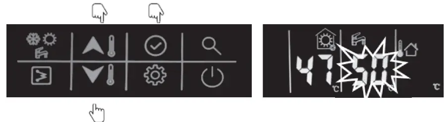
Press the confirm button ![]() or wait for 5s without pressing any button to enter the setting value of LWT. Next, press the “up” or “down” button to change the setting of LWT
or wait for 5s without pressing any button to enter the setting value of LWT. Next, press the “up” or “down” button to change the setting of LWT
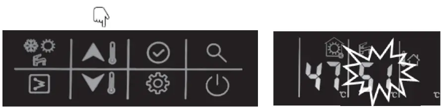
Here are the steps to change the air setpoint control: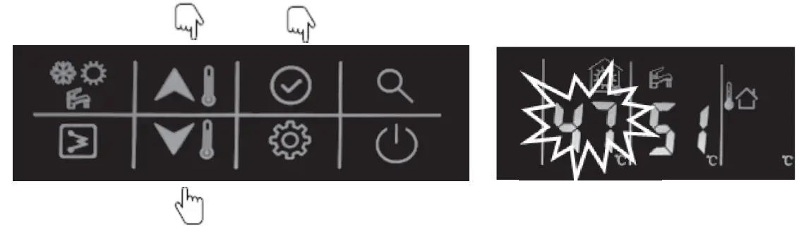
Here are the steps to change the air setpoint control:
- While in standby mode or operating in cooling/heating mode:
First press the “up” or “down” button to change the air setpoint;
Next, press the confirm button or wait for 5s without pressing any button to change the DHW temperature setting. Next, press the “up” or “down” button to change the DHW. - While operating in DHW mode:
First press the “up” or “down” button to change the temperature of DHW;
- Press the confirm button or wait for 5s without pressing any button to enter the setting value of LWT. Next, press the “up” or “down” button to change the air setpoint.
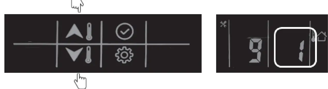
Home/away/eco setting
To optimize the energy efficiency of the building, you can select the occupancy mode manually according to the following steps. Each occupancy mode is associated with a pre-defined temperature range.
- Press the “setting” button to item 5: Select Occupancy mode
- Press the “up” or “down” button to change the value. (0-Home; 1-Eco; 2-Away)
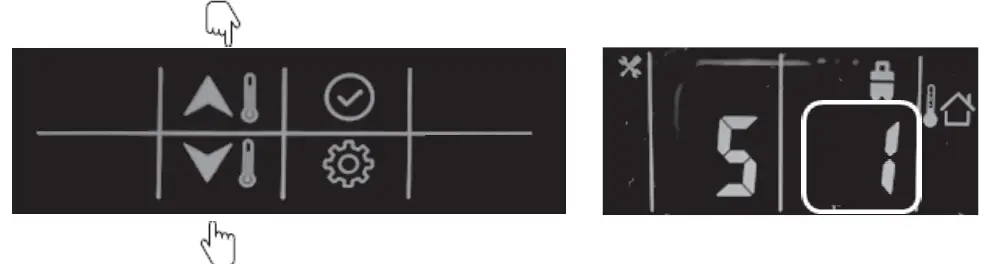
- Next, press “confirm” to confirm and exit user setting or you can also press the “setting” button to go to the next item. (Refer to the user parameter configuration for the full parameter setting details)
Example: Eco mode
![]() This icon lights up on selecting eco mode.
This icon lights up on selecting eco mode.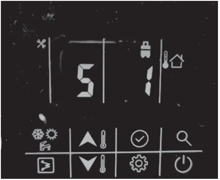
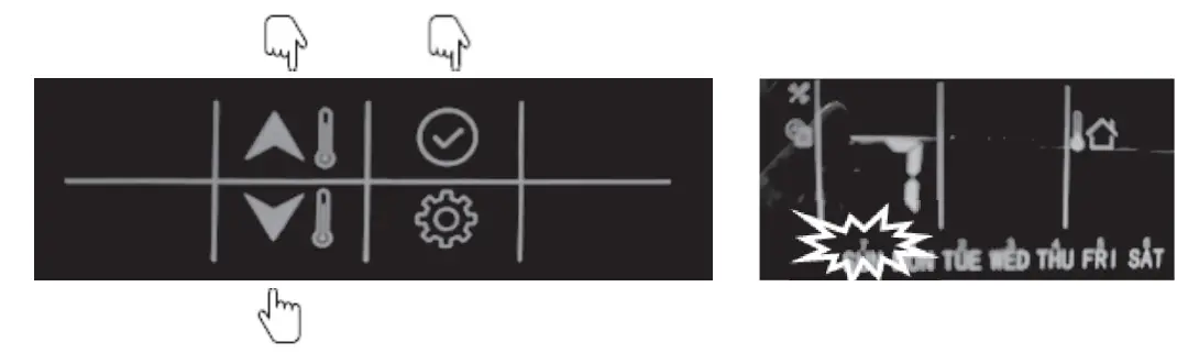
DHW schedule setting
This schedule is used to set the operating of DHW mode automatically according to the timed schedule. Please follow the steps below to set the DHW schedule
- Press the “setting” button to item 1: DHW schedule setting.
- Press and hold the “confirm” button; the icon “on” will flash, then press the “confirm” button to confirm, the icon “on” will light up constantly;

- Press and hold the “down” button to enter the date settings, then press “up” or “down” to select the day, press “confirm” to confirm day settings, after that, the icon of that day will light up constantly;

- Press and hold the “down” button to enter the hour settings, then press “up” or “down” to select the time in hours; press “confirm”.

- Press and hold the “down” button to enter minute settings, then press “up” or “down” button to select the time in minutes and press “confirm”.
- Press and hold the “down” button to set the timer off, then press the “down” button to enter hour settings. Press the “up” or “down” button to select the time in hours and press “confirm”.
- Press and hold “down” button to enter minute settings, then press “up” or “down” to select the time in minutes and press “confirm”.
- Press and hold “confirm” button to confirm and exit user settings. You can also press “settings” button to go to the next item.
Refer to the user parameter configuration for all parameter settings)
Example
The unit will operate the DHW mode at 22:00 from Monday to Friday and will exit the DHW mode automatically at 6:00 from Tuesday to Saturday.
| Schedule of DHW mode | |||||||
| Day | Monday | Tuesday | Wednesday | Thursday | Friday | Saturday | Sunday |
| √ | √ | √ | √ | √ | × | × | |
| Time on | 22:00 | 22:00 | 22:00 | 22:00 | 22:00 | 22:00 | 22:00 |
| Time off | 6:00 | 6:00 | 6:00 | 6:00 | 6:00 | 6:00 | 6:00 |
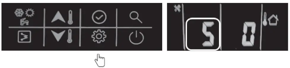
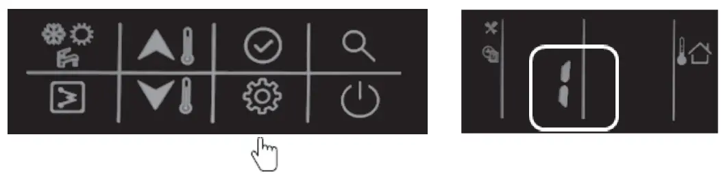
Button lock settings
Used to lock the button of wired controller in case of touching by mistake; double press the “settings” button to unlock.
- Press the “setting” button to go to item 9: wired controller button lock.

- Press the “up” or “down” button to set the value (0-unlock; 1-lock)
- Next, press “confirm” button to confirm and exit user setting or you can also press “settings” button to go to next item. (Refer to the user parameter configuration for all parameter settings)
Configuration
This wired controller can be used to configure the system setting during installation and operation. Here follow two configuration sections: user parameters configuration and technical parameters configuration, please check the details in 3.1 & 3.2.
User parameter configuration
Press the “settings” button to enter the user parameters configuration interface and press this button to page down the setting items from 0-9 as circuit. Use the “up” or “down” button to change the value of each item.
Details of the user parameters configuration table are given below: (The No. in the table below will be displayed in the left LED tube except “0”)
| No. | Item | Description | |
| 0 | Clock settings | ① ② ③ ④ | Press the “settings” button and then press “confirm” to enter date settings andthen press “up” or “down” button to change the date if necessary;Next, press “confirm” to enter hour settings, press “up” or “down” to set the correcttime in hours;Next, press “confirm” to enter minute settings and press “up” or “down” button toset the correct time in minutes.Press “confirm” to confirm and exit clock settings.You can also press “settings” button to go to the next parameter. |
| 1 | Schedule of DHW | ① ② ③ ④ ⑤ ⑥ | Press and hold the “confirm” button, the icon “on” will flash, then press “confirm”,and the “on” icon will light up constantly;Press and hold the “down” button to enter day settings, then press “up” or “down”button to select the day, press “confirm”, and the icon will remain lit up;Press and hold the “down” button to enter hour settings, then press “up” or “down”to select the time in hours, press “confirm”.Press and hold the “down” button to enter minute settings, then press “up” or“down” to select the time in minutes and press “confirm”.Press and hold the “down” button to set the timer off, then press the “down” button to enter hour settings, then press “up” or “down” button to select the time in hours, and press “confirm”.Press and hold “down” button to enter minute settings, then press “up” or “down”to select the time in minutes, press the “confirm” button to confirm;Press and hold “confirm” to confirm and exit user settings. You can also press the“settings” button to go to the next item. |
| 2 | Power memory setting | This is used to record the settings if power is shutdown, and the system will recover the previous status once power is back.① Press “up” or “down” button to set the value; 0- With power memory (default);1- Without power memory | |
| 3 | WIFI Status | Reserved | |
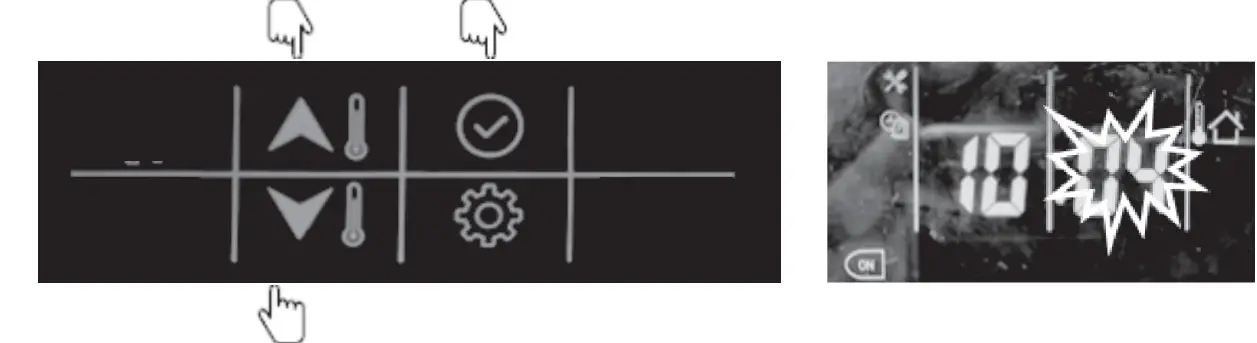
| 4 | Air purge mode | ①0-1- | Press the “up” or “down” button to set the value; Do not start air purge modeStart air purge modeIf choosing 0, then press the “settings” button to go to the next item; |
| If choosing 1, then press the “confirm” button to exit the settings and unit will startthe air purge mode; during the air purge mode, wired controller will be displayed “PA”, and only the “ON/OFF” button are valid to exit this mode. | ||
| 5 | Occupancy mode setting | ① Press “up” or “down” button to set the value;② Then press “confirm” button to confirm and exit user settings or you can alsopress “settings” button to go to the next item.0- Home; 1- Eco; 2- Away |
| 6 | Night mode setting | This is used to set up night mode for low noise during the night-time. Press “up” or “down” button to set the value:0- Without night mode 1- With night modeIf choosing 0, press “confirm” and exit user settings or you can also press “settings”button to go to the next item;If choosing 1, then follow the steps below:① Press “confirm” button to set the start timer setting, then press “up” or “down”button to set the time in hours;② Press “confirm” to enter minute setting, then press “up” or “down” button to setthe time in minutes;③ Press the “confirm” button to enter the stop timer setting, then press “up” or“down” button to set the time in hours;④ Press “confirm” button to enter minute settings, then press “up” or “down” buttonto set the time in minutes;⑤ Next, press “confirm” to confirm and exit user settings or you can also press the“settings” button to go to the next item. |
| 7 | Anti-legionella temperature setting | Press the “up” or “down” button to set the value; Temperature range: 60-700C, default as 600C. |
| 8 | Anti-legionella timer starts | ① Press and hold “confirm” button to enter day settings, press “down” button to set the day, then press the “confirm” button to confirm, after which the icon of the day will remain lit up.② Press and hold the “down” button to enter hour settings, then press “up” or “down”button to select the time in hour, press the “confirm” button to confirm.③ Press and hold the “down” button to enter minute settings, then press “up” or“down” button to select the time in minutes and press “confirm”.④ Press and hold the “confirm” button to confirm and exit user settings or you canalso press “settings” button to go to the next item. |
| 9 | Lock of wired controller | Used to lock the button of wired controller in case children touch by mistake; double press the “settings” button to unlock.① Press the “up” or “down” button to set the value;② Next, press the “confirm” button to confirm and exit user settings or you can alsopress the “settings” button to go to the next item.0- Without lock1- With lock |
Technical parameter configuration
Press and hold the “setting” button to enter the technical parameter configuration interface and press the “setting” button to turn down the setting items from 0-25. You can use “up” or “down” button to change the value of each item.
Details of the user parameter configuration are given below:
| No. | Item | Description |
| 0 | Control setpoint type | 0- Water setpoint control 1- Air setpoint control |
| 1 | Controller selection | 0- Wired controller1- Dry contact |
| 2 | Back up function | 0- Main water loop EHs + DHW EHs + boiler 1- Main water loop EHs + DHW EHs2- DHW EHs + boiler3- Main water loop EHs + boiler 4- DHW EHs only5- Boiler only6- Main water loop EHs only 7- Non back up |
| 3 | Climate curve selection | 0- Non climate curve 1- Climate curveAfter setting 1 with climate curve, please follow the below steps:① After choosing 1, enter heating climate setting, press “up” or “down” to choose fromclimate curves 1-13, if choosing between 1-12, press “confirm” and then go to step③; if choosing 13, press “confirm” and then go to step ②;.② Customized heating curve value input:a. Press “up” or “down” to set the value of MinOAT;b. Press “confirm” button to set MaxOAT, press “up” or “down” to setthe value of MaxOAT;.c. Press “confirm” to set MinWSP, press “up” or “down” to set thevalue of MinWSP;d. Press “confirm” to set MaxWSP, press “up” or “down” to set thevalue of MaxWSP;e. Press “confirm” to go to step ③.③ Press the “up” or “down” button to set the heating climate offset from -5~50C, default as 00C; then press “confirm” to go to step p ⑥④ Enter cooling climate settings; press the “up” or “down” button to choose between climate curves 1-3, if choosing 1-2, press “confirm”, then go to step ⑥ ; if choosing 3, press “confirm” to go to step ⑤.⑤ Customized heating curve value input:a. Press “up” or “down” to set the value of Min OAT;. b. Press “confirm” to set Max OAT, press “up” or “down” to set the value ofMax OAT; |
| c. Press “confirm” to set Min WSP, press “up” or “down” to set the value ofMin WSP;d. Press “confirm” \to set Max WSP, and press “up” or “down” to set the value ofMax WSP;e. Press “confirm” to go to step ⑥.⑥ Press the “up” or “down” button to set the heating climate offset from -5~50C, default as 00C; then press “confirm” to confirm and exit or “setting” button to go to the next item. | ||
| 4 | Capacity test setting | Reserved |
| 5 | 3-way valve type select | 0- Normal open1- Normal closed |
| 6 | DI1 | 0- Disable1- Power limitation (night mode) 2- Load-shed3- DHW request4- Anti-legionella request5- HDW priority |
| 7 | DI2 | |
| 8 | DI3 | |
| 9 | DI4 | |
| 10 | DO1 | 0- Disable1- Unit in alarm2- Unit in standby 3- Unit running4- Unit in cooling 5- Unit in heating 6- Unit in DHW7- Unit in defrost8- Unit controlled by Modbus |
| 11 | DO2 | |
| 12 | DO3 | |
| 13 | Eco mode cooling setpoint offset | If air setpoint is chosen, it is air setpoint offset, otherwise, it is water setpoint offset 0~100C, default as 20C |
| 14 | Away mode cooling setpoint offset | If air setpoint is chosen, it is air setpoint offset, otherwise, it is water setpoint offset 0~100C,, default as 40C15 |
| 15 | Eco mode heating setpoint offset | If air setpoint is chosen, it is air setpoint offset, otherwise it is water setpoint offset-20~00C, default as -20C |
| 16 | Away mode heating setpoint offset | If air setpoint is chosen, it is air setpoint offset, otherwise, it is water setpoint offset-20~00C, default as -40C |
| 17 | Eco mode DHWsetpoint offset | -10~00C, default as -50C |
| 18 | Minimum OAT for heating | -26~100C, default as -260C |
| 19 | Booster OAT Threshold | -10~00C, default as -50C |
| 20 | Heat pumpwarmup time | 0~120min, default 60min |
| 21 | Booster Deltatemperature | 1~200C, default 100C |
| 22 | Second zone setting | 0 – No bi-zone function1- Bi-zone function for heating mode only2- Bi zone function for both cooling and heating modes |
| No. | Item | Description |
| 23 | Water pump ΔT control setting | ΔT default as 50C, can be adjusted from 3.50C~80C, with precision 0.50C |
| 24 | Water pump controltype setting | 0- ΔT control 1-Force to on 2- Force to off |
| 25 | Water pump speed setting | If the item 24 (last setting item) is set to 1 – force to on, then you can set this item 25, in this case you can choose the value from 0-99, which means the water pump speed is from 1%-100%0- 1% speed1- 2% speed…99 – 100% speed |
NOTE:
DI: Customized input, dry contact;
DO: Customized output, 230V contact;
All the settings will be changed only by resetting and never by repowering.
Parameter and status checking
Parameter and status checking
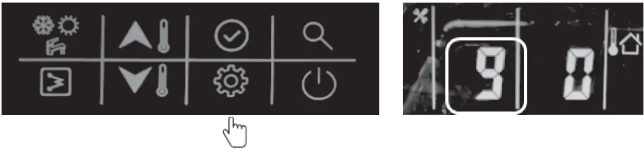
This wired controller can be used to check the system status and running parameters. Press the “query” button to enter the parameter query interface, and press “confirm” or don’t press any button for more than 10s to exit the parameter query interface.
After going into query interface, press “up” or “down” to check the parameters or status as given in the table below:
| No. | Definition | Description |
| 1 | Setting temp.: Ts1 | Display Ts1 during standby/cool/heat mode |
| 2 | Setting temp.: Ts2 | Display Ts2 during DHW mode |
| 3 | Setting temp.: Ts3 | Display Ts3 when it chooses the air setpoint control |
| 4 | Capacity of unit | HP*10, example: 10 means that unit is at 1HP capacity |
| 5 | Target frequency | |
| 6 | Running frequency | |
| 7 | Water flow rate | m3/h, feedback from inverter water pump |
| 8 | Capacity output | =1.163* (water flow rate) * [Tw_out – Tw_in] (kW) |
| 9 | T3 value | ODU coil temp. |
| 10 | T4 value | OAT |
| 11 | TP value | Discharged temp. |
| 12 | T7 value | Temp. of refrigerant for PCB cool |
| 13 | EVX opening degree | Actual value |
| 14 | ODU fan motor speed | |
| 15 | AC current | |
| 16 | AC voltage | |
| 17 | IPM temp. (T9) | Compressor module temp. |
| 0: no limitation; | ||
| 1: T3B temp. limitation (reserved); | ||
| 2: OAT limitation; | ||
| 4: Discharged temp. limitation; | ||
| 18 | Limitation reason of compressor frequency | 8: Voltage limitation16: Current limitation |
| 32: IPM temp’ limitation | ||
| 64: Night mode limitation | ||
| 128: LWT limitation | ||
| If multi limitation occurs, display value=sum of all limitation values | ||
| 19 | Limitation reason for compressor frequency | 0: no limitation;1: Limitation of different values between EWT & LWT |
| 20 | Tw_in value | EWT |
| 21 | Tw_out value | LWT of BPHE |
| 22 | T1 value | LWT of unit (after the EHs inside the unit) |
| 23 | T6 value | IAT, the sensor built inside the wired controller |
| 24 | T5 value | DHW value |
| 25 | Tw-2 value | Second zone EWT value when this function is set (reserved) |
| 26 | T1B value | External heat source (boiler) LWT value |
| 27 | Capacity demand | |
| 28 | Inv. Pump speed | |
| 29 | Last alarm | |
| 30 | Penultimate alarm | |
| 31 | Antepenultimate alarm | |
| 32 | Current protection | P0-P3: check the details in the alarm table |
33 | Detail of P6 alarm in function board | L-: no alarm;L0: IPM or IGBT over current; L1: lack of phaseL2: Compressor losing speed fault; L3: DC voltage is too low to protect L4: Fan motor over current protection L5: Fan motor lack of phase;L6: Fan motor zero speed fault L7: PFC faultL8: DC voltage is too high to protect L9: Compressor zero speed fault LA: PWM synchronization faultLb: MCE faultLc: Compressor over current protection Ld: EEPROM data is wrongLE: Compressor fails to start; LF: fan motor losing speed fault |
| 34 | SV2 statue of water loop | This is a 2-way valve which is used to cut off the heating terminal waterloop once the unit is running cooling mode (OFF- 0; ON- 1) |
| 35 | SV3 statue of water loop | DHW 3-way valve |
| 36 | Main water loop EHs statue | Standard equipment with one EH; the other two are field supplies(OFF-0; ON-1) |
| 37 | DHW EHs | OFF-0; ON-1 |
| 38 | External heat source statue | OFF-0; ON-1 |
| 39 | P_m | External main water loop pump (OFF-0; ON-1) |
| 40 | P_p | Second zone water loop pump (OFF-0; ON-1) |
| 41 | P_o | First zone water loop pump (OFF-0; ON-1) |
| 42 | Anti-frozen heater statue | OFF-0; ON-1 |
| 43 | Chassis heater statue | OFF-0; ON-1 |
| 44 | Crank heater statue | OFF-0; ON-1 |
| 45 | SV2 statue of refrigerant system | FCU water loop valve, to cut off water supply to radiator/spaceheater coil in cool mode (OFF-0; ON-1) |
Error code
This wired controller also functions as the detector to display the unit alarm as outlined in the following table: Example: E1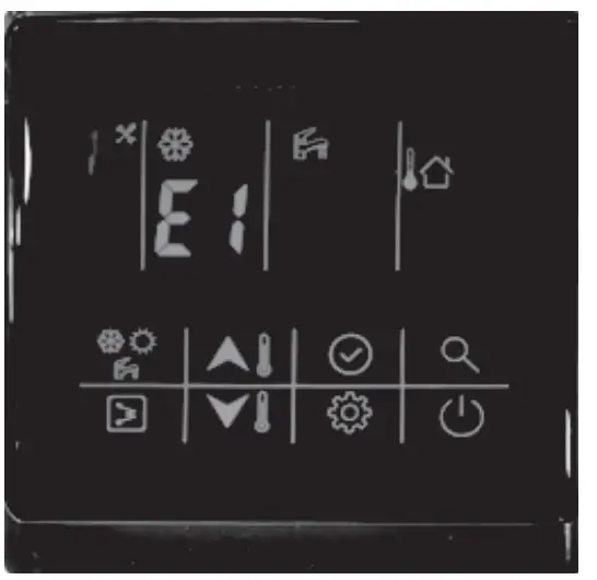
![]() This icon will light up once the alarm sounds.
This icon will light up once the alarm sounds.
| Alarm code | Description |
| E0 | Water flow switch fault |
| E1 | Communication fault between IDU board and ODU board |
| E2 | LWT of unit sensor (T1 sensor) fault |
| E3 | Gas refrigerant temp sensor (T2 sensor) fault (reserved) |
| E4 | Liquid refrigerant temp sensor (T2B sensor) fault (reserved) |
| E5 | ODU (module part) alarm |
| E6 | DHW sensor (T7 sensor) fault |
| E7 | LWT sensor (T_in sensor) fault |
| E8 | LWT of BPHE sensor (T_out sensor) fault |
| E9 | Communication fault between wired controller and function board |
| EA | Second zone LWT sensor (Tw_2 sensor) fault (Only valid after setting second zone function, reserved) |
| Eb | External heat source LWT sensor (T1B sensor) fault (Only valid after setting the external heat source – boiler) |
| Ec | Water pump fault |
| Ed | Reserved |
| EE | Reserved |
| EF | Mode conflict (reserved) |
| P0 | EEPROM fault |
| P1 | Protection from huge different values between EWT and LWT |
| P2 | Protection from lack of water |
| P3 | Protection from abnormal different values between EWT and LWT |
| P6 | Protection from standard electrical heater overheat |
802058000056
CR-SA-XKQENG12-2
Manufacturer: Guangdong Carrier Heating, Ventilation & Air Conditioning Company Limited Address: N0.1, Helangsha, Shengli Village, Lishui Town, Nanhai District, Foshan, Guangdong Province, China Order No: 10192, 12.2019 – Supersedes order No: 10192, 01.2019. Manufacturer reserves the right to change any product specifications without notice


