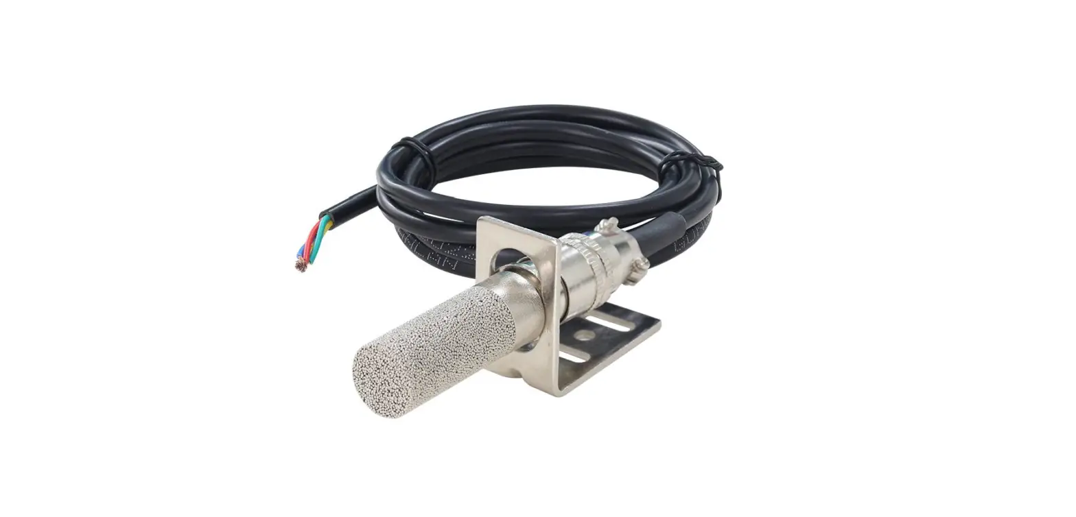
 sonbus QM7820C mounted temperature and humidity sensor
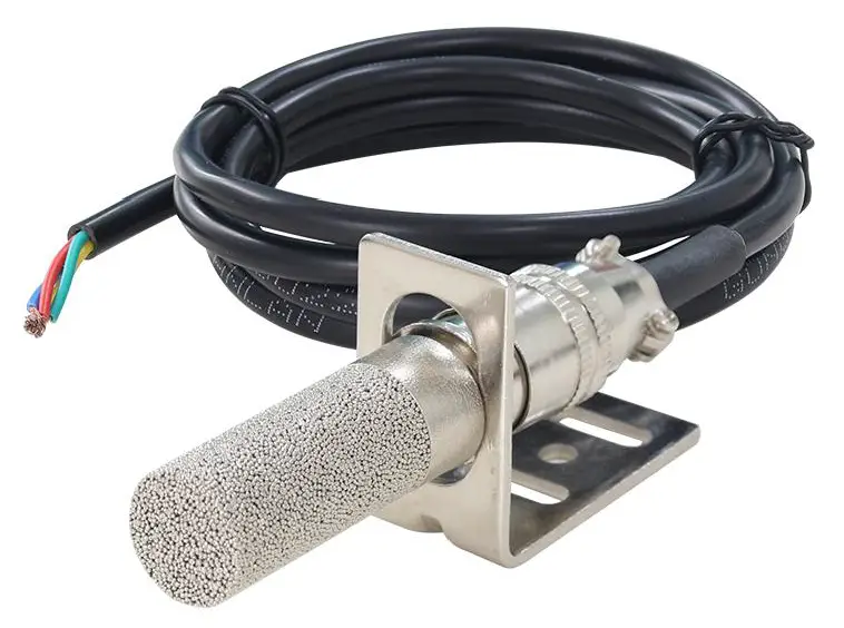
QM7820C using the standard CAN Bus,easy access to PLC, DCS and other instruments or systems for monitoring temperature, and humidity state quantities.The internal use of high-precision sensing core and related devices to ensure high reliability and excellent long-term stability can be customized
Technical Parameters
| Technical parameter | Parameter value |
| Brand | TRANBALL |
| Temperature measuring range | -30℃~80℃ |
| Temperature measuring accuracy | ±0.5℃ @25℃ |
| Humidity measuring range | 0~100%RH |
| Humidity accuracy | ±3%RH @25℃ |
| Communication Interface | CAN |
| Default rate | 250kbps |
| Power | DC5~24V 1A |
| Running temperature | -40~80°C |
| Working humidity | 5%RH~90%RH |
Product Size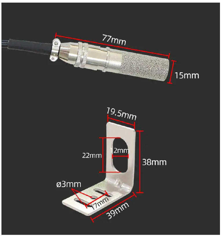
How to wiring?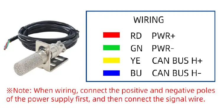
Application solution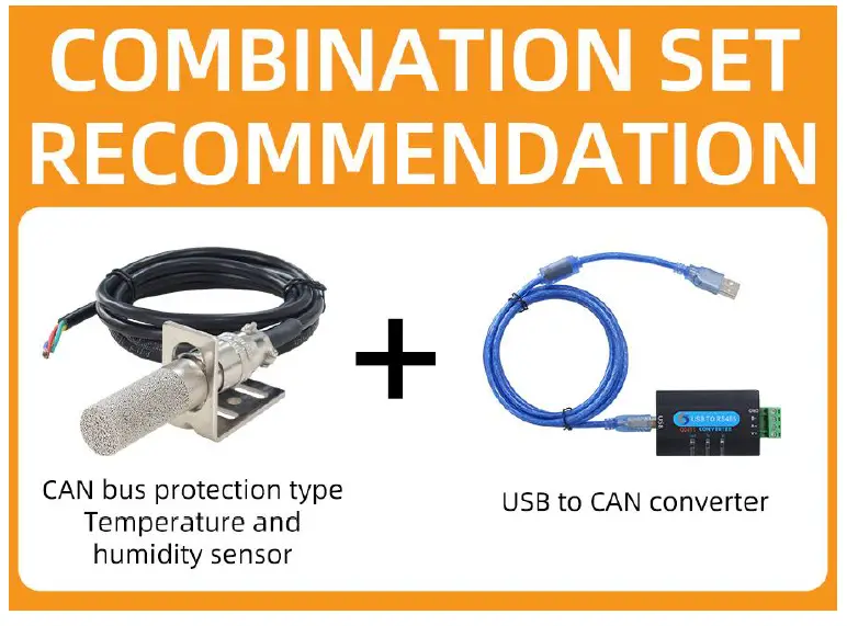

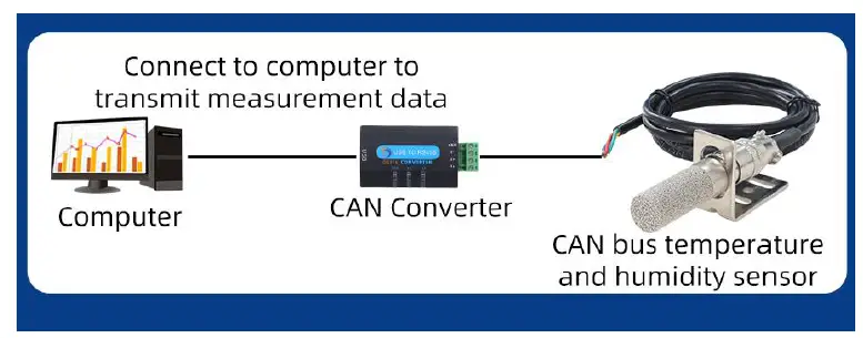
How to use?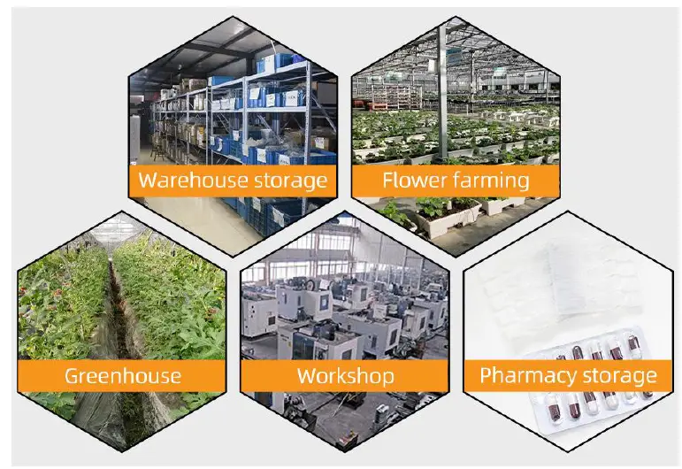
Communication Protocol
The product uses the CAN2.0B standard frame format. The standard frame information is 11 bytes, including two parts of information and the first 3 bytes of the data part are the information part. The default node number is 1 when the device leaves the factory, which means The text identification code is
ID.10-ID.3 in the CAN standard frame, and the default rate is 50k. If other rates are required, they can be modified according to the communication protocol. The device can directly work with various CAN converters or USB acquisition modules. Users can also choose our industrial-grade USB-CAN converters (as shown in the figure above). The basic format and composition of the standard frame are as follows As shown in the table.
| 位 | 7 | 6 | 5 | 4 | 3 | 2 | 1 | 0 |
| Byte 1 | FF | FTR | X | X | DLC.3 | DLC.2 | DLC.1 | DLC.0 |
| Byte 2 | ID.10 | ID.9 | ID.8 | ID.7 | ID.6 | ID.5 | ID.4 | ID.3 |
| Byte 3 | ID.2 | ID.1 | ID.0 | x | x | x | x | x |
| Byte 4 | d1.7 | d1.6 | d1.5 | d1.4 | d1.3 | d1.2 | d1.1 | d1.0 |
| Byte 5 | d2.7 | d2.6 | d2.5 | d2.4 | d2.3 | d2.2 | d2.1 | d2.0 |
| Byte 6 | d3.7 | d3.6 | d3.5 | d3.4 | d3.3 | d3.2 | d3.1 | d3.0 |
| Byte 7 | d4.7 | d4.6 | d4.5 | d4.4 | d4.3 | d4.2 | d4.1 | d4.0 |
| Byte 11 | d8.7 | d8.6 | d8.5 | d8.4 | d8.3 | d8.2 | d8.1 | d8.0 |
Byte 1 is the frame information. The 7th bit (FF) indicates the frame format, in the extended frame, FF=1; the 6th bit (RTR) indicates the type of the frame, RTR=0 indicates the data frame , RTR=1 means the remote frame; DLC means the actual data length in the data frame. Bytes 2~3 are valid f or 11 bits of the message identification code. Bytes 4~11 are the actual data of the data frame, invalid for the remote frame . For example, when the hardware address is 1, as shown in the figure below, the frame ID is 00 00 00 01, and the data can be responded by sending the correct command.
- Query data
Example: To query all 2 data of 1# device channel 1, the host computer sends the command: 01 03 00 00 00 02.
| Frame type | CAN frame ID | mapping address | function code | starting address | data length |
| 00 01 | 01 | 01 | 03 | 00 00 | 02 |
Response frame: 01 03 04 07 3A 0F 7D.
| Frame type | CAN frame ID | mapping address | function code | data length | data |
| Response frame | 00 00 | 01 | 03 | 04 | 08 AD 0F 7D |
In the query response of the above example: 0x03 is the command number, 0x4 has 4 data, the first data is 08 AD converted into decimal system: 2221, because the module resolution is 0.01, this The value needs to be divided by 100, that is, the actual value is 22.21 degrees. Each data occupies two bytes, that is, an integer variable. The actual value needs to be divided by 100 on the basis of this value. Similarly, 0F 7D is the second data. Its value is 3965, that is, the true value is 39.65.
Change Frame ID
You can use the master station to reset the node number by command. The node number ranges from 1 to 200. After resetting the node number, you must reset the system. Because the communication is in hexadecimal format, the data in the table Both are in hexadecimal format.
For example, if the host ID is 00 00 and the sensor address is 00 01, the current node 1 is changed to the 2nd. The communication message for changing the device ID is as follows: 01 06 0B 00 00 02.
| Frame type | Frame ID | Set Address | Function id | fixed value | target frame ID |
| Command | 00 01 | 01 | 06 | 0B 00 | 00 02 |
Return frame after correct setting: 01 06 01 02 61 88. The format is as shown in the table below
| Frame ID | Set Address | Function id | source frame ID | current frame ID | CRC16 |
| 00 00 | 01 | 06 | 01 | 02 | 61 88 |
The command will not respond correctly. The following is the command and reply message to change the Set Address to 2.
Change device rate
You can use the master station to reset the device rate through commands. The range of the rate number is 1~15. After resetting the node number, the rate will take effect immediately. Because the communication is in hexadecimal format, the rate in the table The numbers are in hexadecimal format.
| Rate value | actual rate | rate value | actual rate |
| 1 | 20kbps | 2 | 25kbps |
| 3 | 40kbps | 4 | 50kbps |
| 5 | 100kbps | 6 | 125kbps |
| 7 | 200kbps | 8 | 250kbps |
| 9 | 400kbps | A | 500kbps |
| B | 800kbps | C | 1M |
| D | 33.33kbps | E | 66.66kbps |
The rate not in the above range is not currently supported. If you have special requirements, you can customize it. For example, the device rate is 250k, and the number is 08 according to the above table. To change the rate to 40k, the number of 40k is 03, the operation communication message is as follows: 01 06 00 67 00 03 78 14, as shown in the figure below.
After the rate modification is performed, the rate will change immediately, and the device will not return any value. At this time, the CAN acquisition device also needs to switch the corresponding rate to communicate normally.
Return frame ID and rate after power-on
After the device is powered on again, the device will return the corresponding device address and rate information. For example, after the device is powered on, the reported message is as follows: 01 25 01 05 D1 80.
| Frame ID | device address | function code | current frame ID | current rate | CRC16 |
| 00 00 | 01 | 25 | 00 01 | 05 | D1 80 |
In the response frame, 01 indicates that the current frame ID is 00 01, and the speed rate value 05 indicates that the current rate is 50 kbps, which can be obtained by looking up the table.
Disclaimer
This document provides all information about the product, does not grant any license to intellectual property, does not express or imply, and prohibits any other means of granting any intellectual property rights, such as the statement of sales terms and conditions of this product, other issues. No liability is assumed. Furthermore, our company makes no warranties, express or implied, regarding the sale and use of this product, including the suitability for the specific use of the product, the marketability or the infringement liability for any patent, copyright or other intellectual property rights, etc. Product specifications and product descriptions may be modified at any time without notice.
Contact Us
Company: Shanghai Sonbest Industrial Co., Ltd TRANBALL Brand Division Address:Building 8,No.215 North east road,Baoshan District,Shanghai,China Web: http://www.qunbao.com
Web: http://www.tranball.com
SKYPE: soobuu
Email: [email protected]
Tel: 86-021-51083595 / 66862055 / 66862075 / 66861077


