circle FITNESS Sp8 Indoor Cycle Owner’s Manual
ATTENTION:
Read instructions carefully, failure to do so may cause permanent damage to your bike.
Please verify that all parts associated with this product are in good condition and accounted for.
During the assembly process please be sure to follow each step accordingly as it has been explained within the manual.
Safety Instructions
- Consult your physician before starting with any exercise program to receive advice on the optimal training.
- Warning: incorrect/ excessive training can cause health injuries. Stop using the bike when feeling uncomfortable.
- Please follow the advice for correct training as detailed in the training instructions.
- Ensure that training only starts after correct assembly, adjustment and inspection of the bike.
- Always start with a warm-up session.
- Only use original parts as delivered.
- Follow the steps of the assembly instruction carefully.
- Only use suitable tools for assembly and ask for assistance if necessary.
- Place the bike on an even, non-slippery surface.
- For all adjustable parts be aware of the maximum position to which they can be adjusted.
- Tighten all adjustable parts to prevent sudden movement while training.
- This product is designed for adult. Please ensure that children only use it under supervision of an adult.
- Ensure that those present are aware of possible hazards, e.g. movable parts during training.
- The resistance level can be adjusted to your personal preference.
- Do not use the bike without shoes or loose shoes.
- Ensure that sufficient space is available to use the bike.
- Be aware of non-fixed or moving parts whilst mounting or dismounting the bike.
- To protect the floor or carpet from damage, place a mat under the exercise bike.
- In case of emergency please place both feet at the same time on the side reins.
- Ensure that an area of 2000 x 1000 mm behind the exercise bike is free from any obstacles.
- This product is tested up to a maximum body weight of 150 kilograms.
- We take no responsibility for personal injury or damage sustained by or through the use of this exercise bike.
SAFETY INFORMATION
- Keep children and pets away from this equipment at all times. DO NOT leave them unsupervised in the room where the machine is kept.
- If you experience dizziness, nausea, chest pains or any other symptom while using this machine STOP the exercise. SEEK IMMEDIATE MEDICAL ATTENTION!
- Keep your hands away from any of the joints and moving parts.
- Wear clothing suitable for doing exercise. Do not wear baggy clothing that might get caught in the machine. Always wear athletic shoes when using the machine and tie the laces securely.
- This machine must only be used for the purposes described in this manual. DO NOT use accessories that are not recommended.
- Do not place sharp objects near the machine.
- Any person with physical or coordination limitations should not use the machine without the assistance of a qualified per son or doctor.
- Do not use the machine if it is not working correctly.
- Before using the machine, thoroughly inspect the equipment for proper assembly.
- Use only authorized and trained technicians if a repair is needed.
- Use only the tools provided to assemble this machine.
- This machine can only be used by one person at a time.
- The moving pedals can cause injury.
Caution: Consult your doctor before beginning to use the machine or any exercise program. Read all of the instructions before using any exercise equipment. KEEP THESE INSTRUCTIONS SAFE FOR FUTURE USE.
![]() CAUTION: During assembly it is recommended that all bolts be tightened by hand, upon completing assembly, bolts should then be properly secured using the wrench provided. To avoid injury, check bolts carefully before use.
CAUTION: During assembly it is recommended that all bolts be tightened by hand, upon completing assembly, bolts should then be properly secured using the wrench provided. To avoid injury, check bolts carefully before use.
Assembly
Step one
Attach the front foot tube (18) first by lifting up the front of the frame and sliding the front foot tub under the frame. Align the holes of the tube and frame then insert bolt (10) from below. Secure the bolt with washer (9) and nut (b8) use the wrench. Use the same procedure to secure the rear foot tube (14)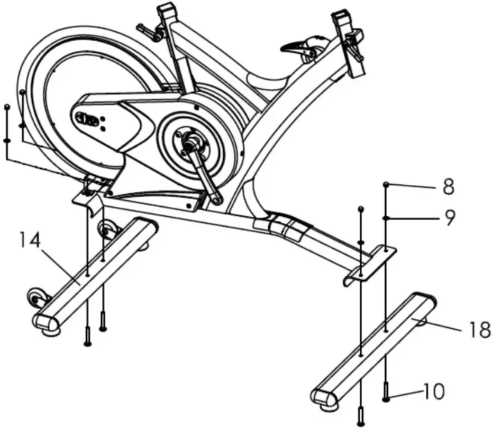
Step two
Attach the handlebar post (22) by inserting it into the head tube of the frame. Use the release lever (6) to adjust and tighten the height to the desired position. Attach the handlebar slider (23) on the handlebar post (22), use release lever (17) to adjust and tighten the handlebar into position. Install the clamp (67) on the handlebar and insert the console (64) to the clamp (67), then connect the cable (65) to the back of the console (64) and make sure the other side of the console cable (65) is connected securely to the cable coming from the frame. After the cable is connected, put cable connectors into frame hole then plug cable stopper (69) to frame.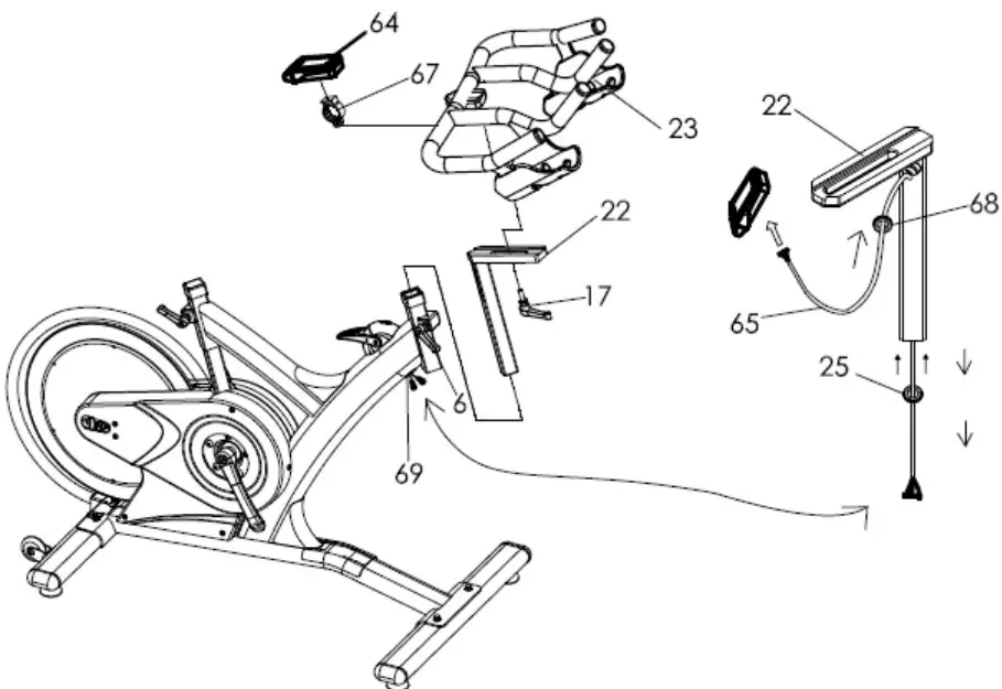
Step three
Insert the seat post (43) into the seat tube on the frame. Attach the saddle (1) into seat slider (42). Then tighten seat clamp’s nut. Insert the seat slider (42) into the seat post (43) and fix. Loose the release lever (6) to adjust the height and distance in the desired position, and tighten it finally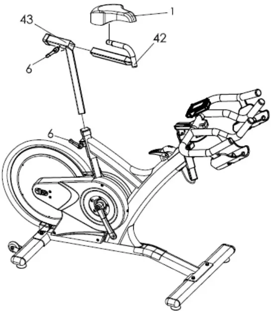
Step four
Attach the pedals (11) into the crank arms (20)(21), each pedal is marked with L (left) or R (right), make sure it’s assembled on the correct side. (R: means rider’s right side). Be careful to align the threads correctly to avoid damaging them. Applying a little grease on the threads will help the pedals to screw in easily and correctly, tighten using a 15mm spanner; both pedals should tighten towards the front of the spinning bike.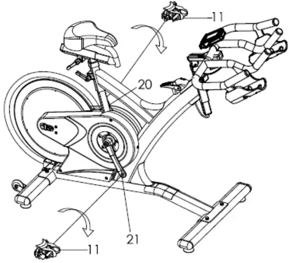
Right Pedal
Please make sure pedal in your hand is the right pedal before Installation. Please refer to the figure. Align the right pedal with right crank at 90 degree. Gently insert the pedal in the crank arm. Turn the pedals clockwise as tightly as you can with your hand. Use the wrench to ensure it is tightened securely. Please always tighten by hand first, then finish by wrench.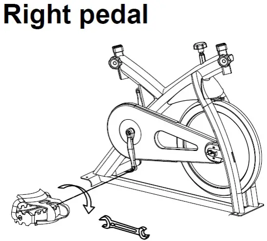
Left Pedal
Please make sure pedal in your hand is the left pedal before Installation. Please refer to the figure. Align the left pedal with left crank at 90 degree. Gently insert the pedal in the crank arm. Turn the pedals counter- lockwise as tightly as you can with your hand. Use the wrench to ensure it is tightened securely. Please always tighten by hand first, then finish by wrench.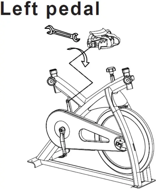
Remark:
Riding this bike backwards may loosen the pedals which will damage the threads. Please always check pedals to ensure that the pedals are tightened. If the pedals have become loose, tighten threads with the wrench to ensure they are securely attached.
Adjusting the resistance
Adjust the exercise resistance on the spinning bike using the tension knob (24) to loosen (-) or tighten (+).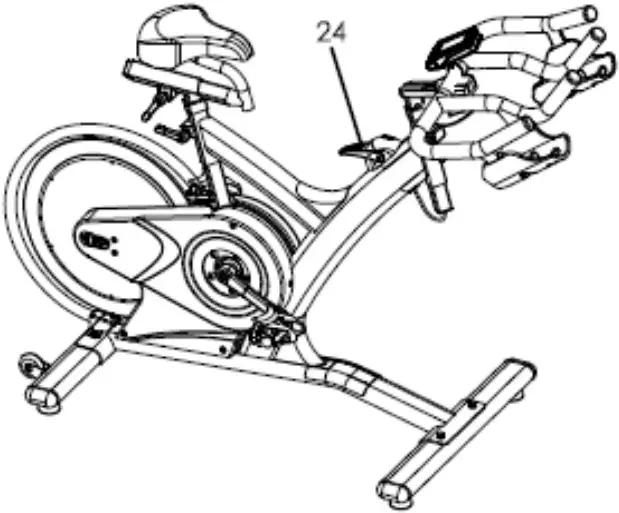
Stability
If the floor is not even, you can adjust theheight by foot tube adjuster pad (13) to make it firmly.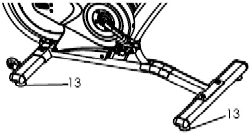
MOVING
There are moving wheel (39) located in rear foot tube (14) for easy to moving the machine.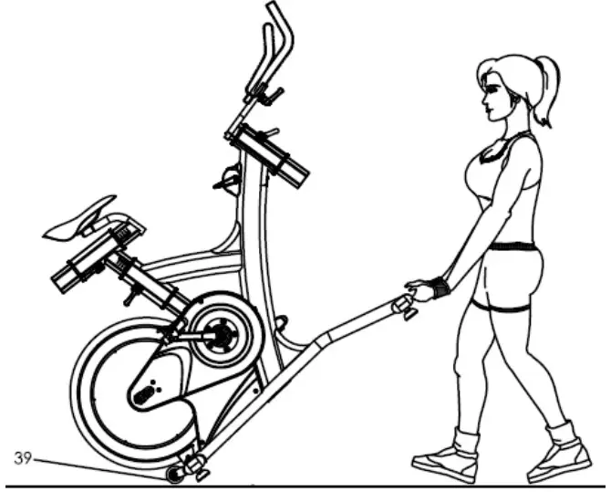
Exploded Drawing
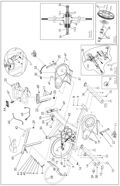
| No. | Name | Unit | No. | Name | Unit |
| 1 | Saddle | PC | 35 | Flywheel axle | SET |
| 2 | Alloy bind clamp ( L ) | PC | 36 | Fixed wheel nut | |
| 3 | Spring for release lever | PC | 37 | Flywheel bearing | |
| 4 | Alloy bind clamp ( R ) | PR | 15,15-115-2 | Flywheel security washer & nut | |
| 5 | Washer for release lever | PC | 63 | Rubber cover for flywheel | |
| 6 | Release lever | PC | 38 | Axle bolt for moving wheel | PC |
| 7 | Crank bolt | PC | 39 | Moving wheel | PC |
| 8 | Foot tube nut | PC | 40 | Plastic washer for release lever | PC |
| 9 | Foot tube washer | PC | 41 | Fixed bolt for release lever | PC |
| 10 | Foot fixing bolt | PC | 42,29 | Seat slider w/ end plug | PC |
| 11 | Pedal | PR | 43 | Seat post | PC |
| 12 | Front / Rear foot tube end cap | PC | 44 | Washer for release lever | PC |
| 13 | Foot tube adjuster pad | PC | 45 | Belt | PC |
| 14 | Rear foot tube Complete | PC | 47 | Outer chain guard bolt M5 | PC |
| 16 | Flywheel adjuster bolt | PC | 48 | Bolt for protection tube | PC |
| 17 | Handle bar release lever w/washer | PC | 49 | Flywheel (complete) | SET |
| 18 | Front foot tube Complete | PC | 50 | Rubber sleeves | PC |
| 19 | Right belt guard | PC | 51 | Fixed bolt for tension knob casing | PC |
| 20 | Left crank arm | PC | 52 | Idler w/bearing, clip | SET |
| 21 | Right crank arm | PC | 53 | Rubber sealed | PC |
| 22 | Handle bar post | PC | 54 | Handle for tension knob | PC |
| 23 | Handle bar w/slider | PC | 55 | Casing for tension knob | PC |
| 24 | Tension knob set (complete) | SET | 56 | Bolt for tension knob handle | PC |
| 25 | End cap for handlebar post | PC | 58 | Flywheel protection tube | PC |
| 27 | Adjuster cable guide | PC | 61 | Belt pulley with screw, magnet | PC |
| 28 | Brake pad | PC | 63 | Rubber cover for flywheel | PC |
| 29 | End plug for seat slider | PC | 64 | Console complete set | SET |
| 30 | C Rubber sealed | PC | 65 | Upper cable | PC |
| 31 | Left belt guard | PC | 66 | Sensor cable | PC |
| 32 | Washer for protection tube | PC | 67 | Clamp for console | PC |
| 33 | BB bearing | PC | 68 | Rubber eyelet | PC |
| 34 | BB Axle with plate | PC | 69 | Cable plug | PC |
| 36 | Flywheel security nut | PC | G01 | Magnetic brake set, brake pad | SET |
Instruction
It is important that the handlebar and seat are set at the correct height for your body. Ask your instructor for assistance.
Handlebar adjustment – Adjusting the handlebar height-Undo the adjuster release lever that is located at head tube (where the handlebar post fits into the frame). Slide the handlebar post up or down to the required height and retighten the adjuster release lever. Make sure it is securely tightened and that there is no lateral or vertical movement of the handlebar. The handlebar position can also be adjusted forwards or backwards. Undo the release lever located below the handlebar slider. Slide the handlebar assembly forwards and backwards until you reach the required position. Then securely re-tighten the release lever. Pay attention on ”MIN INSERT” mark for safety adjustment.
Seat adjustment – Undo the adjuster release lever located at seat tube (where the seat post fits into the frame). Adjust the seat to the required height. Then retighten the adjuster release lever. The seat position can be adjusted forwards and backwards. Undo the adjuster release lever located directly side of the seat slider. Loosen the adjuster release lever then slide the seat to the required position. Then make sure the adjuster release lever retighten.
Pay attention on ” MIN INSERT” mark for safety adjustment.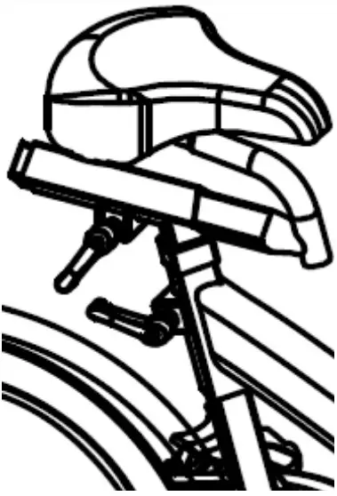
Saddle:
Make sure tighten enough for both side of nut after adjust the saddle position. To prevent the saddle from twisting side to side.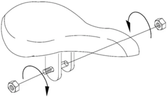
Emergency Brake:
Pushing the RED lever (54) of the Tension knob (24) forward completely for emergency brake.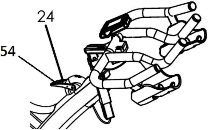
Maintenance Chart
※ Adjusting the belt tension:
- Loosen the bolt (47), and take off the belt guard (19, 31).
- Loosen the nut (36).
- Turn the nut of the adjuster bolt (16) to adjusting the belt tension. Suggest turn 1/4 circles each time.
Don’t turn too much to causing tension too tight then damage the axle and bearings.
Please make sure this step be performed on both left & right sides and the adjustment distance is the same. After adjusted, Make sure flywheel keeps parallel with frame and in the middle position. - After finished the above steps, screw the nut (36) by both sides. Make sure the nut is tighten and fixedly.
Computer Instructions
DISPLAY FUNCTION:
| ITEM | DESCRIPTION |
| SCAN |
|
| SPEED |
|
| RPM |
|
| TIME |
|
| DISTANCE |
|
| CALORIES |
|
| WATT |
|
| LOAD |
|
| PULSE |
|
| SET |
|
| MODE/ENTE R |
|
| RESET |
|
| RECOVERY |
|
OPERATION PROCEDURE
POWER ON
- LCD will display all segments as Drawing 1.
- Monitor working display as Drawing 2.
- When adjust LOAD, the monitor will display as Drawing 3.
Drawing 1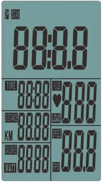
Drawing 2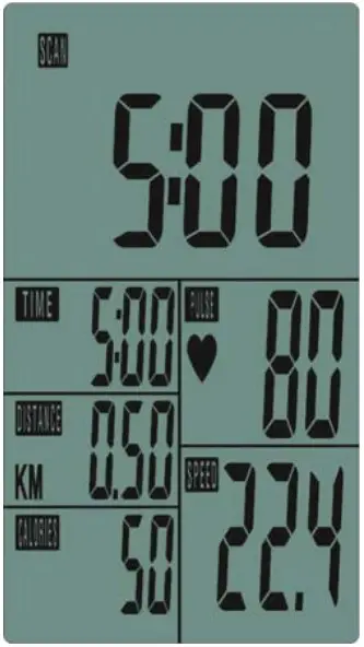
Drawing 3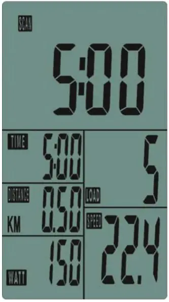
POWER OFF
Without any signal being transmitted into the monitor for 4 minutes the monitor will enter SLEEP mode.
OPERATION
Workout setting
- Press MODE/ENTER key to select the function of TIME, DISTANCE,CALORIES and PULSE. Use SET Key for setting and press MODE key for confirmation.
- For instance the time set-up, when the time value is blinking, you can use SET Key to adjust the number. Press MODE/ENTER key for confirmation and skip to next set-up. The set-up of DISTANCE/ CALORIES and PULSE is the same as TIME set-up.
- Once the workout begins and the console picks up the exercise signal, the value of SPEED/RPM, TIME, DST, CAL and PULSE will count up on the display.
Recovery
- The RECOVERY key will only be valid if pulse is detected.
- TIME will show “0:60” (seconds) and counts down to 0. Computer will show F1 to F6 after the countdown to test heart rate recovery status. User can find the heart rate recovery level based on the chart below.
- Press RECOVERY key again to return to the beginning.
| F1 | Outstanding |
| F2 | Excellent |
| F3 | Good |
| F4 | Fair |
| F5 | Below average |
| F6 | Poor |
Trouble shooting
- When the display of LCD is dim, it means the batteries need to be changed.
- If there is no signal when you pedal, please check if the cable is well connected.
NOTE:
- When stop training for 4 minutes, the main screen will be off.
- If the computer displays abnormally, please re-install the batteries and try again.
APP


- This console can connect APP on the smart device by Bluetooth.
- Once console is connect to smart device via Bluetooth, the console will power off.