Autonics TCD210228AH LSC Series 2D Laser Scanners
Product Information
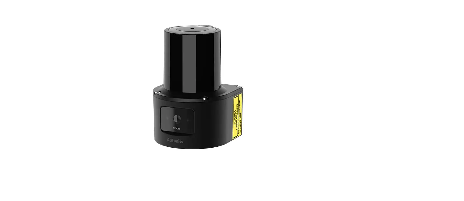
The Transparent Guide LSC Series is a laser scanner product used for collision avoidance in various machinery and devices such as nuclear power control, medical equipment, ships, vehicles, railways, aircraft, combustion apparatus, safety equipment, crime / disaster prevention devices, etc. It should be used with a fail-safe device to prevent serious injury or substantial economic loss. This product is not a safety sensor and does not observe any domestic nor international safety standard. It should not be used for injury prevention or life protection or in places where economic loss may be expected.
The scanner should not be used in the place where flammable / explosive / corrosive gas, high humidity, direct sunlight, radiant heat, vibration, impact, or salinity may be present to prevent fire or explosion. The laser emitter should not be stared at to prevent eye damage. The scanner must be used within the rated specifications to avoid fire or product damage. When cleaning the scanner, a dry cloth should be used instead of water or organic solvent to prevent fire.
Product Usage Instructions
Before using the Transparent Guide LSC Series, make sure to carefully read and understand the safety considerations and cautions specified in the user manual to prevent injury, fire, or product damage.
When setting up the scanner, follow the ordering information and select the specified model by checking the Autonics website. The product components may be sold separately depending on the model selected.
The scanner’s network settings should be configured with the following IP address, subnet mask, and gateway:
- IP address: 192.168.0.1
- Subnet mask: 255.255.255.0
- Gateway: 192.168.0.2
When connecting the scanner, use the Power I/O connector wiring (M12 12-pin connector, Plug-Male) following the signal function of each pin specified in the user manual. The Ethernet connector wiring (M12 8-pin-RJ45 connector, Plug-Male) should also be connected following the signal specified in the manual.
When using the scanner for collision avoidance, set the field considering the speed of the moving object, the braking distance, and the response time of the laser scanner. Choose a field set for output when the object is detected in subfield 1, subfield 2, or subfield 3.
Thank you for choosing our Autonics product.
Read and understand the instruction manual and manual thoroughly before using the product.
For your safety, read and follow the below safety considerations before using. For your safety, read and follow the considerations written in the instruction manual, other manuals and Autonics website.
- Keep this instruction manual in a place where you can find easily.
- The specifications, dimensions, etc. are subject to change without notice for product improvement. Some models may be discontinued without notice.
- Follow Autonics website for the latest information.
Safety Considerations
- Observe all ‘Safety Considerations’ for safe and proper operation to avoid hazards.
- warning: symbol indicates caution due to special circumstances in which hazards may occur.
Warning: Failure to follow instructions may result in serious injury or death.
- Fail-safe device must be installed when using the unit with machinery that may cause serious injury or substantial economic loss. (e.g. nuclear power control, medical equipment, ships, vehicles, railways, aircraft, combustion apparatus, safety equipment, crime/disaster prevention devices, etc.) Failure to follow this instruction may result in economic loss, personal injury or fire. Do not use the unit in a place where flammable/explosive / corrosive gas, high humidity, direct sunlight, radiant heat, vibration, impact, or salinity may be present.
Failure to follow this instruction may result in fire or explosion. - This product is not safety sensor and does not observe any domestic nor international safety standards.
- Do not use this product with the purpose of injury prevention or life protection, as well as in a place where economic loss maybe expected. Do not connect the unit while connected to a power source.
Failure to follow this instruction may result in fire. - Check connections and connect cables.
Failure to follow this instruction may result in fire. - Do not disassemble or modify the unit.
Failure to follow this instruction may result in fire.
Caution: Failure to follow instructions may result in injury or product damage.
- Do not stare at the laser emitter.
Failure to follow this instruction may result in eye damage. - Use the unit within the rated specifications.
Failure to follow this instruction may result in fire or product damage. - Use dry cloth to clean the unit. Do not use water or organic solvent whencleaning the unit.
Failure to follow this instruction may result in fire. - Do not apply high pressure to the laser scanner to clean it.
- As collision avoidance function for a moving object, set the field considering the speed of the moving object, the braking distance, and the response time of the laser scanner.
Cautions during Use
- Follow instructions in ‘Cautions during Use’. Otherwise, it may cause unexpected accidents.
- Power supply should be insulated and limited voltage / current or Class 2, SELV power supply device.
- After supplying power, the sensor performs self-check for about 10 sec. When selfchecking, error occurrence, and teaching, the laser scanner outputs the same as it sensed obstacle.
- In order to avoid malfunction from static electricity or noise, ground shield wire of the power I/O cable or housing fixing screws.
- Mutual optical interference between laser scanners and photoelectric sensors may result in malfunction.
- Mutual optical interference between laser scanners may result in malfunction.
- Objects cannot be scanned when covering the front cover of the laser scanner.
- When the laser scanner is moved to another position, use it after re-teaching.
- Do not drop the unit. It may cause malfunction.
- Installing the laser scanner in the place where smoke, fog, dust, or corrosion is heavy may result in malfunction.
- Keep away from high voltage lines or power lines to prevent inductive noise. In case of installing power line and input signal line closely, use line filter or varistor at power line and shield wire at input signal line.
- Do not use the laser scanner near the equipment which generates strong magnetic force or high frequency noise.
- Cover with shields, hoods, or etc. to prevent direct incidence of strong light (direct rays of sunlight, incandescent) into the laser scanner beam spread angle.
- Fix the laser scanner in position with the fixing screw. Vibration may result in malfunction
- When IP address of the laser scanner and wireless router is same, the communication does not connected. Set the wireless network (Wifi) to “Disable” in the network settings of the Windows operating system.
- This unit may be used in the following environments.
- Indoors (in the environment condition rated in ‘Specifications’)
- Altitude max. 2,000 m
- Pollution degree 2
- Installation category II
Ordering Information
This is only for reference, the actual product does not support all combinations. For selecting the specified model, follow the Autonics website.
![]()
Detection distance
Number: Detection distance (unit: m)
Product Components
- Product
- M3 × 8 mm bolt (SUS) × 4
- Instruction manual
- Connector cap × 1
Sold Separately
- Power I / O cable: CID-□-VG, CLD-□-VG
- Ethernet cable: C18-□R-A, C48-□R-A
Network Setting
- Configure the network settings of LiDAR sensor via atLiDAR.
- For initial IP address, refer to the table as below.
| IP address | 192.168.0.1 |
| Subnet mask | 255.255.255.0 |
| Gateway | 192.168.0.2 |
Connections
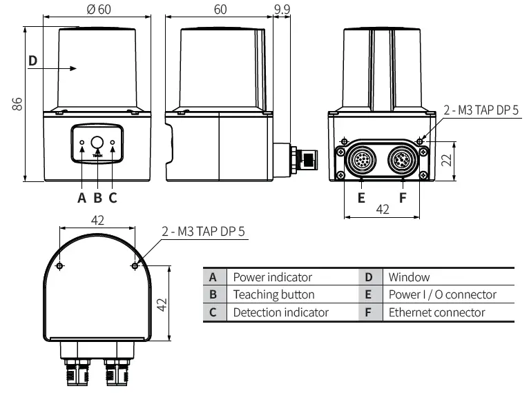
Power I / O connector wiring (M12 12-pin connector, Plug-Male)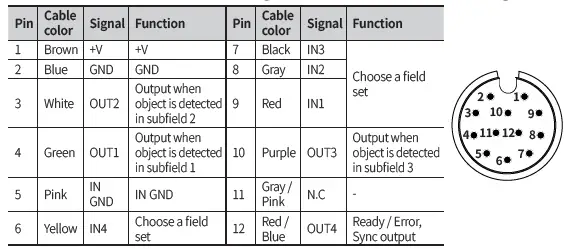
Ethernet connector wiring (M12 8-pin-RJ45 connector, Plug-Male)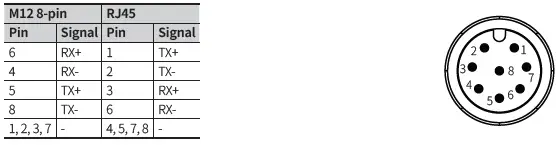
Input / Output Specifications
Input specifications
The input operates with rising/falling edge and H / L level and can be selected.
| Input | Options | Descriptions |
| IN1 | Select field set | – |
| IN2 | Select field set | – |
| IN3 01) | Select field set or Scan input | It can be used as scan start and stop signal. |
| IN4 01) | Select field set or Teaching | It can be used as an external input signal for teaching. |
- Default: Select field set
Output specifications
The output operates at PNP / NPN and can be selected. RESTART sets to time.
| Output | Descriptions |
| OUT1 | Subfield 1 output |
| OUT2 | Subfield 2 output |
| OUT3 | Subfield 3 output |
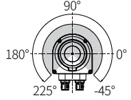
| OUT4 01) | Ready / Error output fixed Sync pulse output at 90° |
- Refer to the scan angle image in Cautions for Installation.
Software
Download the installation file and the manuals from the Autonics website. Supported devices are different for each software version.
atLiDAR (V2.0 or later)
atLiDAR is the management program for laser scanner parameter settings, status information and monitoring data, etc. This program communicates with the laser scanner via Ethernet communication.
ROS driver package
This is a ROS driver package that helps to receive laser scanner information and set ROS (Robot Operating System) parameters without additional settings.
Dimensions
- Unit: mm, For the detailed drawings, follow the Autonics website.

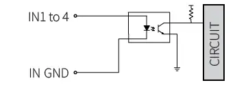
Circuit
Photocoupler input
- NPN open collector output
- PNP open collector output
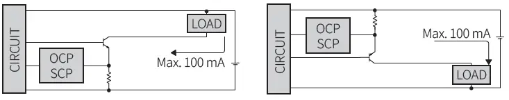
- OCP (over current protection), SCP (short circuit protection)
- If short-circuit the control output terminal or supply current over the rated specification, normal control signal is not output due to the output short over current protection circuit.
Installation Order
For details of atLiDAR settings, refer to the software manual.
- Install the laser scanner.
Secure the device to the installation location using four M3 × 8 mm bolts. - Install the laser scanner program to PC.
Download the software provided by Autonics website. - Connect the laser scanner and the PC, and set the network.
Refer to the Network Setting. - Laser scanner function setting
Use atLiDAR, set each function to adequate the installation environment of the laser scanner and the obstacles to be detected.
Cautions for Installation
- Install the unit correctly with the usage environment, location, and the designated specifications.
- Impact with hard objects or excessive bending of the wire lead-out may result in damage on the waterproof function.
- Use this device after testing. Check if the indicator is working properly depending on whether the obstacle exists.
- Install the unit according to the direction you want to detect the object.

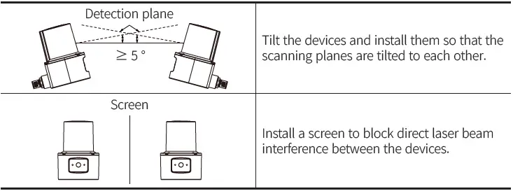
- To prevent mutual interference when installing multiple devices, refer to the below.

Manual
For proper use of the product, refer to the manuals and be sure to follow the safety considerations in the manuals.
Download the manuals from the Autonics website.
Indicators
| Status | Indicator | Other description | ||
| Power (green) | Detection (red) | |||
| Power on | Light on then off | When the power is applied normally, it turns off. | ||
| Normal operation | ON | – | – | |
| ERROR | – | Flashing | – | |
| Obstacle detection | ON | ON | – | |
|
Teaching | Step 1 | Flashing 01) | – | Teaching preparation stage : Start teaching with the teaching button, IN4 signal or software. |
| Step 2 | Flashing 02) | Flashing 02) | Teaching progress stage : There must be no moving objects in the teaching area. | |
| Step 3 | ON | – | Turns on after teaching is completed. (normal operation) | |
| Apply parameters | Flashing (once) | Flashing (once) | Flashes during application of parameters set by software. | |
- Teaching preparation stage time selection among 5 / 10 / 15 sec by software
- Teaching progress stage time selection among 10 / 20 / 30 / 40 / 50 / 60 sec by software
Specifications
| Model | LSC-C5CT3-ET | LSC-C10CT3-ET | LSC-C25CT3-ET |
| Environment of use | Indoor | ||
| Emitting property | Infrared laser | ||
| Laser class | CLASS 1 | ||
| Wave length band | 905 nm | ||
| Max. pulse output power | 6 W | ||
| Beam conversion angle | 9.5 mrad | ||
| Scanning frequency | 15 Hz | ||
| Response time | Typ. 67 ms | ||
| Detection distance range | 0.05 to 5 m | 0.05 to 10 m | 0.05 to 25 m |
| Max. detection distance of 10 % reflector | 5 m | 8 m | |
| Detection distance error | System error: Typ. ± 60 mm, statistical error: Typ. 20 mm (1 σ) | ||
| Min. object size 01) | At detection distance of 8 m: ≈ 121 mm | ||
| Angular resolution | 0.33° | ||
| Aperture angle | 270° | ||
| Object reflectivity | > 4 % | ||
| Number of field sets | 16 (1 set: Consists of subfields 1, 2, 3) | ||
| Number of field sets that can be used concurrently | 1 | ||
| Unit weight (package) | ≈ 228 g (314 g) | ||
| Approval | |||
- Even objects smaller than the set min. object size can be detected depending on the environment.
| Power supply | 9 – 28 VDC |
| Power consumption 01) | < 4 W |
| Input | 4 Photocoupler inputs H: ≥ 9 – 28 VDC, L: ≤ 3 VDC |
| Output signal | 4: 3-output + 1-Ready / Error, Sync output NPN-PNP open collector output (software setting) |
| Load voltage | 9 – 28 VDC |
| Load current | ≤ 100 mA |
| Residual voltage | ≤ 3.0 VDC |
| Insulation resistance | ≥ 5 MΩ (500 VDC megger) |
| Dielectric strength | 500 VAC 50 / 60 Hz for 1 minute |
| Vibration | 10 sweep cycles in each X, Y, Z axes at sine wave, 10 to 500 Hz, acceleration 5 G |
| Vibration (malfunction) | 10 minutes in each X, Y, Z axes at sine wave, 10 to 500 Hz, acceleration 5 G |
| Vibration (irregular) | 5 hours in each X, Y, Z axes at 5 to 250 Hz, 42.4 m/s2 RMS |
| Shock | 3 times in each X, Y, Z axes at sine half wave, acceleration 50 G, duration 11 ms |
| 1000 times in each X, Y, Z axes at sine half wave, acceleration 25 G, duration 6 ms | |
| 5000 times in each X, Y, Z axes at sine half wave, acceleration 50 G, duration 3 ms | |
| Shock (malfunction) | 6 times in each X, Y, Z axes at sine half wave, acceleration 50 G, duration 11 ms |
| Ambient illuminance | ≤ 80,000 lx |
| Ambient temperature | -10 to 50 ℃, storage: -30 to 70 ℃ (no freezing or condensation) |
| Ambient humidity | 0 to 95 %RH, storage: 0 to 95 %RH (no freezing or condensation) |
| Protection structure | IP67 (IEC standard) |
| Connector specification | Power I / O: M12 12-pin, Ethernet: M12 8-pin |
| Material | Case: AL, Window: PC |
Communication Interface
Ethernet
| Communication protocol | TCP/IP |
| Communication speed | 100BASE-TX |
| Baud rate | 100 Mbps |
CONTACT
Address: 18, Bansong-ro 513Beon-gil, Haeundae-gu, Busan, Republic of Korea, 48002
www.autonics.com |
+82-2-2048-1577 |
[email protected]


