
![]()
INSTRUCTION MANUAL
MODEL: PAV-EX40-HDR-ARC-AE

OVERVIEW
The PAV-EX40-HDR-ARC-AE-KIT is a premium HDMI extender featuring HDBaseT technology, allowing for the extension of 4K HDR HDMI signals up to 40 Meters with Audio Return allow- ing for audio from a display or separate playback device to be returned to the Additionally, the PAV-EX40-HDR-ARC-AE-KIT is equipped with Bi-directional POC, IR, RS232, and comprehensive EDID management the PAV-EX40-HDR-KIT creating the ultimate integrator tool for any installation.
MODEL NUMBERS
- PAV-EX40-HDR-ARC-AE-T – HDBaseT Transmitter w/ IR, RS232, and Audio Return
- PAV-EX40-HDR-ARC-AE-R – HDBaseT Receiver w/ IR, RS232, and Audio Return
FEATURES
- HDMI 0b
- Max Resolution 4K60 4:4:4
- HDCP X/2.2 Support
- CEC Pass-Through
- Audio Return Channel (ARC)
- Multichannel Extracted Audio
- Up to 40M (Cat6a) at 4K
- Up to 70M (Cat6a) at 1080p
- Bi-Directional POC
- 3-20V IR Support with Direct Control System Support
- Bi-Directional RS232 Transport
- Supports audio formats up to uncompressed LPCM 1, Dolby TrueHD (including Atmos), and DTS (up to DTS:X)
PACKAGE CONTENTS
- Power Supply
- X2 Mini TOS to TOS Adaptor
- X2 IR Target (Eye/Receiver)
- X2 IR Blaster (Emitter)
- X2 Velcro Strip
- Mounting Brackets
- X2 5MM TRS (Stereo) to Open Cable
SPECIFICATIONS
VIDEO
| Video Resolutions | Up to 4K60 4:4:4 |
| VESA Resolutions | Up to 4096X2160 (DCI 4K) |
| Chroma Supported | 4:4:4, 4:2:2, 4:2:0, RGB (Limited and Full) |
| Deep Color | Up to 16 Bit (1080p) Up to 12 Bit (4K) |
| HDR Support | HDR10, HDR10+, HLG, Dolby Vision |
AUDIO
| LPCM (Up to 192KHz 24 bit) | 2.0, 5.1, 7.1 |
| Dolby | Dolby Digital, Dolby Digital Plus, Dolby TrueHD, Dolby Atmos |
| DTS | DTS 6.1 ES, DTS HRA, DTS Master Audio, DTS:X |
| HDMI Audio Return Channel (ARC) | Up to Dolby Digital |
HDBASET DISTANCE (CAT 6A)
| 4K Resolutions | 40 Meters (131 Feet) |
| 1080p Resolutions | 70 Meters (230 Feet) |
TRANSMITTER
INDICATOR LIGHTS (FRONT OF UNIT)
Power LED – Indicates that power is connected to the unit.
- Light is On = Power Supply/POC Connected and Unit is operating
- Light is Off = Power Supply is not connected, or no power is present
HDMI Sync LED – Indicates that an HDMI Source is connected to the Transmitter.
- Light is On = HDMI Source is Active on the HDMI Input
- Light is Off = HDMI Input sense no active HDMI Source
HDBaseT Link LED – Indicates that the HDBaseT Transmitter is linked with any HDBaseT Receiver.
- Light is On = Unit has linked with an HDBaseT Receiver and is sending Data
- Light is Off = Unit has not linked with an HDBaseT Receiver
ARC LED – Indicates the State of the Audio Return Channel.
- Light is On = Audio is being sent back from the HDBaseT Extracted Audio is outputting the audio sent back from the HDBaseT Receiver
- Light is Off = Audio is being sent downstream to the Extracted Audio is outputting the audio from the source device
DIP SWITCH TABLE
| EDIT | IR | Audio Selection | |||
| DipSwitch 1-4 | EDIT | Dipswitch 5 | IR Input Selection | Dipswitch 6 | Audio Selection |
| 0000 | EDID Bypass | 0 | IR Target (Eye) | 0 | Audio sent downstream. Extracted Audio Plays from Source |
| 0001 | 1080p 444 2CH | 1 | IR from Control System | 1 | Audio Return from Receiver. Extracted Audio Plays ARC Audio. |
| 0010 | 1080p 444 6CH | ||||
| 0011 | 1080p 444 8CH | ||||
| 0100 | 4K30 444 2CH | ||||
| 0101 | 4K30 444 6CH | ||||
| 0110 | 4K30 444 8CH | ||||
| 0111 | 4K30 HDR 2CH | ||||
| 1000 | 4K30 HDR 6CH | ||||
TRANSMITTER
DIP SWITCH TABLE CONTINUED
| EDIT | IR | Audio Selection | |||
| 1001 | 4K30 HDR 8CH | ||||
| 1010 | 4k60 444 2CH | ||||
| 1011 | 4k60 444 6CH | ||||
| 1100 | 4k60 444 8CH | ||||
| 1101 | 4k60 HDR 2CH | ||||
| 1110 | 4k60 HDR 6CH | ||||
| 1111 | EDID Copy | ||||
RECEIVER
INDICATOR LIGHTS (FRONT OF UNIT)
Power LED – Indicates that power is connected to the unit.
- Light is On = Power Supply/POC Connected and Unit is operating
- Light is Off = Power Supply is not connected, or no power is present
HDMI Sync LED – Indicates that an HDMI Source is connected to the Transmitter.
- Light is On = HDMI Output is connected to an active HDMI Input
- Light is Off = HDMI Output does not sense an active HDMI Input
HDBaseT Link LED – Indicates that the HDBaseT Transmitter is linked with any HDBaseT Receiver.
- Light is On = Unit has linked with an HDBaseT Transmitter and is receiving Data
- Light is Off = Unit has not linked with an HDBaseT Transmitter
ARC LED – Indicates the State of the Audio Return Channel.
- Light is On = Audio is being sent back to the HDBaseT Transmitter
- Light is Off = Audio is being sent downstream to the Display
Audio Selection Dipswitch – When Audio Return is Active; Determines the Audio Input Port.
- TV = Returns Audio coming from a Displays HDMI ARC
- EXT = Returns Audio from the Mini Tos + Analog Combination Port
RS232 CONFIGURATION
- RS232 can be used to pass control signals bi-directionally between any two RS232 compatible Commonly used in extending control from a control system.
- The RS232 ports on the PAV-EX40-HDR-ARC-AE-KIT are pinned null modem:
| Control System | RS232 Port | 3.5MM TRS PIN |
| Receive | Transmit | Tip |
| Ground | Ground | Ring |
| Transmit | Receive | Sleeve |
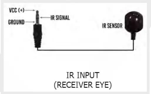
IR CONFIGURATION
IR COMMUNICATION CAN BE SENT TWO WAYS
Downstream (From transmitter)
- Plug an IR Receiving Eye or Control System IR output directly into the IR Sensor port of the PAV-EX40-HDR-ARC-AE-T to pass infrared signals to the IR Out port on the Receiver
- Set IR Dipswitch according to input signal device
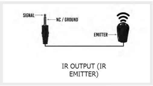
- Connect the IR Out port of the Receiver to an IR Emitter or Direct IR Input
Upstream (From Receiver)
- Plug an IR Receiving Eye into the IR Sensor port of the PAV-EX40-HDR-ARC-AE-R to pass infrared signals to the IR Out port on the Transmitter
- Connect the IR Out port of the Transmitter to an IR Emitter or Direct IR Input

- IR Input (Receiving Eye) (Dipswitch 5 = 0)

- IR Direct Input from Control System (Transmitter Only) (Mono Tip to Tip/ Sleeve to Sleeve) (Dipswitch 5 = 1)

- IR Output to Emitter

TROUBLESHOOTING
TRANSMITTER
No Power LED
- Ensure PSU is sending proper voltage
- If using POC, ensure that the unit sending POC is connected to power
- If using POC, try powering the unit direct to ensure the unit operates stand-alone
No HDMI LED
- Plug Source direct into the display to ensure operability
- Change the resolution of the source device to 1080p or 4K30 (No HDR)
- Set a canned Source may require a power cycle
- Swap HDMI cable between Transmitter and HDMI Handshakes with cables under 2 Meters may not sync properly
TRANSMITTER CONTINUED
No HDBT Link
- Check cable Max Distances are 40M at 4Kor 70M at 1080p. HDBaseT Recommends Cat 6A; Cat 6 and Cat 5e may experience a 5-20% loss of distance
- Remove Excess Service Loops and Bundles of Cable. HDBaseT Recommends up to 6 runs of Cat in a single bundle
- Bypass all patch-panels and punch down blocks
- Re-terminate IP Continuity testers may indicate correct pinouts; However, HDBas- eT Signals are transmitted differently than Ethernet Signals
RECEIVER
No Power LED
- Ensure PSU is sending proper voltage
- If using POC, ensure that the unit sending POC is connected to power
- If using POC, try powering the unit direct to ensure the unit operates stand-alone
No HDMI LED
- Plug Source direct into the display to ensure operability
- Change the resolution of the source device to 1080p or 4K30 (No HDR)
- Set a canned Source may require a power cycle
- Swap HDMI cable between Transmitter and HDMI Handshakes with cables under 2 Meters may not sync properly
No HDBT Link
- Check cable Max Distances are 40M at 4Kor 70M at 1080p. HDBaseT Recommends Cat 6A; Cat 6 and Cat 5e may experience a 5-20% loss of distance
- Remove Excess Service Loops and Bundles of Cable. HDBaseT Recommends up to 6 runs of Cat in a single bundle
- Bypass all patch-panels and punch down blocks
- Re-terminate IP Continuity testers may indicate correct pinouts; However, HDBas- eT Signals are transmitted differently than Ethernet Signals
RS232 TRANSMISSION
- Ensure correct pinout between both the transmitter and receiver A null modem adaptor may be used for quick pinout changing
IR TRANSMISSION
- If sending downstream, ensure dipswitch is in the correct position for Input device type
- The Visible IR Emitters can be used to ensure the signal is being sent from one point to the other
ARC AUDIO
- When using HDMI ARC, ensure that both the AVR and Display have ARC and CEC If the issue continues, try copying the Displays EDID
- Ensure that the correct dipswitch configuration has been selected
- If using Analog audio, ensure that the audio being sent is PCM and not encoded
www.purposeav.ca
[email protected]
(888) 470.2211


