LPSECURITY RDM-900S05 UHF RFID Reader User Manual
Product description
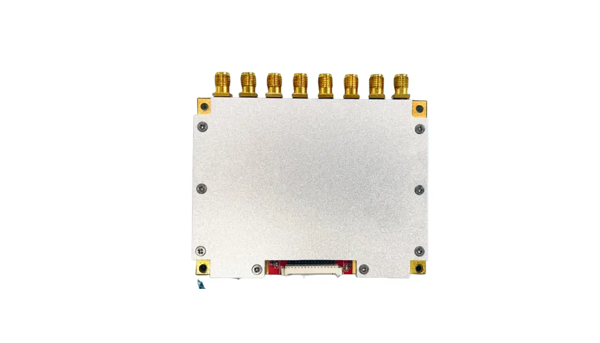
The RDM-900S05 UHF RFID Reader is independently researched and developed by our company and is designed with the industry’s highest performance Impinj R2000 chip. Based on the dynamic Q algorithm of Impinj and brand-new data model, we independently invented the latest “adaptive dynamic Q anti-collision algorithm V3.0” and applied this algorithm to all R2000 readers independently developed by our company. Compared with similar readers in the market, the R2000 reader using this algorithm has significantly improved multi-tag reading performance. The more tags, the more obvious the difference.
The reader has 8 radio frequency SMA antenna connection ports, which can connect 8 antennas at the same time to realize time-sharing cycle inventory. The RDM-900S05 UHF RFID Reader can be used in access control channels, smart containers, high-quality consumables cabinets, tool cabinets, clothing channel machines, filing cabinets and other applications that require multi-antenna identification and reading.
Product advantages
The core chip uses the highest-end performance Impinj R2000 chip
The reader is designed based on the industry’s highest-end performance UHF dedicated chip Impinj R2000
High-performance multi-tag recognition algorithm
Based on the dynamic Q algorithm of Impinj and brand-new data model, we independently invented the latest “adaptive dynamic Q anti-collision algorithm V3.0”. Compared with similar readers in the market, the R2000 reader using this algorithm has significantly improved multi-tag reading performance. The more tags, the more obvious the difference.
Few tags optimization algorithm
An algorithm designed for reading a small number of tags. Ultra-high tag response speed
High power output capability
Choose PA chip with stronger amplifying output ability, the maximum output power of the reader can reach 35dBm. The PA still maintains a linear state when the output is 33dBm. Larger output power can achieve a longer recognition distance, and at the same time, in specific applications, greater output power can activate tags with weaker sensitivity.
Similar Dual-CPU architecture design
The R2000 chip is responsible for polling tags, and the CPU is responsible for data management. Polling tags and sending data are parallel and do not occupy each other’s time. Greatly improve the overall performance.
Fast 8-antenna polling function
High-speed polling 8 antennas. The shortest polling time for each antenna is 50mS. The polling time of each antenna can be configured separately.
Antenna connection detection function
The reader integrated antenna physical connection detection circuit can quickly and accurately detect the antenna connection status of the reader port. The antenna connection status of all ports of the reader can be read with one command.
RF power amplifier PA protection function
The reader integrates forward and reverse power detection functions. When the RF port of the reader is not connected to the antenna, it can quickly detect the status of the unconnected antenna when the tag is read, so as to protect the PA from being burnt out in the case of open circuit output.
Onboard temperature sensor
The onboard high-precision temperature sensor can accurately monitor the temperature
Outstanding thermal design
All the heating devices have a heat-conducting structure. There is a large area of heat sink contact at the bottom of the reader. The thermal coupling interface adopts thermal conductive silicone grease with high thermal conductivity, which is not volatile at high temperature.
Excellent stability
24 hours × 365 days work without crashing. The performance is less affected by the outer shell, electromagnetic environment, etc. Wide temperature design, extremely low temperature drift coefficient.
Excellent consistency
A model of consistent design. All components of the highest level are selected to ensure the stability and consistency of various parameters.
Simple and efficient software and hardware interface
Single power supply, without external tantalum capacitor, the reader can work normally, the peripheral circuit is extremely simple.
Product parameter
Table 3-1 Product parameter table
| Operating Voltage | DC 3.6V ~5 V |
| Standby working current | <50mA (EN pin high level enable) |
| Sleep working current | <100uA (EN pin low level enable) |
| Operating current | 2.1A @ 5V (33 dBm CW Output, 25°C ) 1.5A @ 5V (30 dBm CW Output, 25°C ) average working current 1.7A @ 5V (33dBm Output, real-time inventory mode, 25°C ) |
| Start Time | <50mS |
| Operating temperature | -20 °C ~+70°C |
| Storage temperature | -40 °C ~+85°C |
| Working humidity | <95% (+25 °C) |
| Air interface protocol | EPC global UHF Class 1 Gen 2 / ISO 18000-6C |
| Working frequency | 902MHz~928MHz(USA)、865MHz~868MHz(EU) 860MHz~960MHz(custom working frequency) |
| Supported work area | US, Canada and other regions following U.S. FCC Europe and other regions following ETSI EN 302 208 with & without LBT regulations Mainland China Japan Korea Malaysia Taiwan |
| Output power accuracy | +/- 1dB |
| Output power flatness | +/- 0.2dB |
| Output RF connector | Female(Reverse) SMA |
| Receiving sensitivity | <-85dBm |
| Inventory tag peak speed | ﹥700 tags/second |
| Tag RSSI | support |
| Antenna connection protection | support |
| Working temperature monitoring | support |
| Number of antenna ports | 8 female SMA |
| Communication Interface | TTL UART |
| GPIO | 2 GPIO inputs, 2 GPIO outputs (3.3V TTL level) |
| Communication baud rate | Standard 115200bps (optional 38400bps and 460800bps) |
Precautions:
- When the temperature measured by the working temperature measurement function exceeds 60°C, it is not suitable to work at full load;
- Please connect the heat sink when working continuously at full load;
- The power supply voltage should not exceed 5V, otherwise the internal protection circuit may be damaged;
Pin configuration and function description
1.25mm pitch 15PIN connector pin definition
Figure 4-1 1.27mm pitch connector pin definition
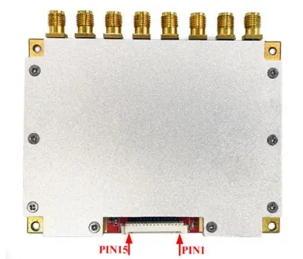
Table 4-1 1.27mm pitch connector pin definition
| PIN | Definition | Description |
| 1 | GND | ground |
| 2 | GND |
| 3 | VCC | power supply DC 3.6V~5V |
| 4 | VCC | |
| 5 | GPIO3 | The first 3.3V TTL level GPIO output |
| 6 | GPIO4 | The second 3.3V TTL level GPIO output |
| 7 | GPIO1 | The first 3.3V TTL level GPIO input |
| 8 | BUZZER | Buzzer control, need external drive (optional internal drive) |
| 9 | UART_RXD | UART RXD(TTL serial port data input) |
| 10 | UART_TXD | UART TXD(TTL serial port data output) |
| 11 | USB_DM | For internal testing only |
| 12 | USB_DP | |
| 13 | GPIO2 | The second 3.3V TTL level GPIO input |
| 14 | EN | High level turns on the reader (default internal pull-up is enabled), low level turns off the reader |
| 15 | 485_DIR | 485 data direction control |
Application information
Input power supply
It is recommended to use at least two 220uF tantalum capacitors with a withstand voltage of 10V or higher for the VCC port to reduce the traction of the power supply due to the rapid opening and closing of the power amplifier during RF transmission. 0.1uF and 100pF capacitors filter out power ripple noise in different frequency bands respectively.
Enable pin
EN is enabled, built-in pull-up resistor to VCC, the reader is powered on when high level or floating, and the reader is powered off when low level(low level should be less than 0.3V, high level should be greater than 1.3V and less than VCC).
GPIO input and output
Input: Logic low<0.56V, minimum 0V; Logic high>1.66V, maximum 3.3V.
Output: Logic low<0.99V, typical 0V; Logic high>2.31V, maximum 3.3V;
IO port maximum output drive current 5mA
Antenna connection
The output impedance of the antenna port is 50 ohms, and the antenna standing wave ratio is recommended to be less than 1.5. A better antenna standing wave ratio can achieve a better card reading effect.
Communication interface(RXD/TXD)
The communication interface RXD and TXD are both 3.3V TTL level, the default baud rate is 115200bps.
Product size parameter
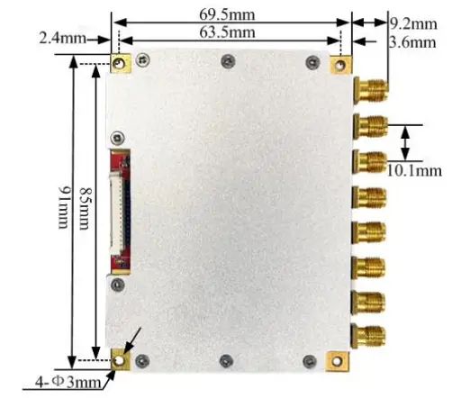
Figure 6-1 Length, width and positioning hole size
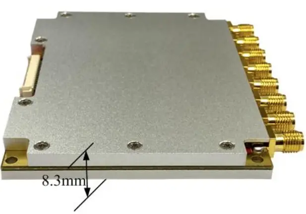
Figure 6-2 PCB, heat sink and shield thickness
FCC Warning
This device complies with part 15 of the FCC rules. Operation is subject to the following two conditions: (1) this device may not cause harmful interference, and (2) this device must accept any interference received, including interference that may cause undesired operation.
Changes or modifications not expressly approved by the party responsible for compliance could void the user’s authority to operate the equipment.
NOTE: This equipment has been tested and found to comply with the limits for a Class B digital device, pursuant to part 15 of the FCC Rules. These limits are designed to provide reasonable protection against harmful interference in a residential installation. This equipment generates uses and can radiate radio frequency energy and, if not installed and used in accordance with the instructions, may cause harmful interference to radio communications. However, there is no guarantee that interference will not occur in a particular installation. If this equipment does cause harmful interferenceto radio or television reception, which can be determined by turning the equipment off and on, the user is encouraged to try to correct the interference by one or more of the following measures:
- Reorient or relocate the receiving antenna.
- Increase the separation between the equipment and receiver.
- Connect the equipment into an outlet on a circuit different from that to which the receiver is connected.
- Consult the dealer or an experienced radio/TV technician for help.
Radiation Exposure Statement
This equipment complies with FCC radiation exposure limits set forth for an uncontrolled environment. This equipment should be installed and operated with minimum distance 20cm between the radiator and your body.


