![]() OWNER’S MANUAL
OWNER’S MANUAL
60 CYCLE
CORROSION RESISTANT SELF-PRIMING
CENTRIFUGAL PUMP
PD2HD-L Corrosion Resistant Self Priming Centrifugal Pump
MODELS – PD2 SERIES
| 3/4 HP | 1 HP | 1-1/2 HP |
| PD2HD-L | PD2HE-L | PD2HF-L |
MODELS – PD SERIES
| 2 HP | 2-1/2 HP |
| PDHG-L | PDHHG-L |
MODEL – PDSS SERIES
1-1/2 HP
PDSSHFT![]() California Proposition 65 Warning
California Proposition 65 Warning![]() WARNING This product and related accessories contain chemicals known to the State of California to cause cancer, birth defects or other reproductive harm.
WARNING This product and related accessories contain chemicals known to the State of California to cause cancer, birth defects or other reproductive harm.
Electrical Safety
![]()
Hazardous voltage.
Can shock, burn, or cause death.
Ground pump before connecting to power supply.![]() Wire motor for correct voltage.
Wire motor for correct voltage.
See “Electrical” section of this manual and motor nameplate.![]() Ground motor before connecting to power supply.
Ground motor before connecting to power supply.![]() Meet National Elec trical Code, Canadian Electrical Code, and local codes for all wiring.
Meet National Elec trical Code, Canadian Electrical Code, and local codes for all wiring.![]() Follow wiring instruc tions in this manual when connecting motor to power lines.
Follow wiring instruc tions in this manual when connecting motor to power lines.
Make workshops childproof; use padlocks and master switches; remove starter keys.![]() CAUTION Do not touch an operating motor.
CAUTION Do not touch an operating motor.
Modern motors are designed to operate at high temperatures. To avoid burns when servicing pump, allow it to cool for 20 minutes after shut-down before handling.
READ AND FOLLOW SAFETY INSTRUCTIONS!
This is the safety alert symbol. When you see this symbol on your pump or in this manual, look for one of the following signal words and be alert to the potential for personal injury:
DANGER warns about hazards that will cause serious personal injury, death or major property damage if ignored.
WARNING warns about hazards that can cause serious personal injury, death or major property damage if ignored.
CAUTION warns about hazards that will or can cause minor personal injury or property damage if ignored.
The label NOTICE indicates special instructions which are important but not related to hazards.
Carefully read and follow all safety instructions in this manual and on pump.
Keep safety labels in good condition. Replace missing or damaged safety labels.
General Safety![]()
![]() WARNING
WARNING
Hazardous pressure!
Do not run pump against closed discharge.
Release all pressure on system before working on any component.
Pump is designed as a lawn sprinkler only. To avoid heat built-up, over pressure hazard and possible injury, do not use in a pressure tank (domestic water) system.
Do not use as a booster pump; pressurized suction may cause pump body to explode.
Do not allow pump or piping system to freeze. Freezing can damage pump and pipe, may lead to injury from equipment failure and will void warranty.
Pump water only with this pump.
Periodically inspect pump and system components.
Wear safety glasses at all times when working on pumps.
Keep work area clean, uncluttered and properly lighted; store properly all unused tools and equipment.
Keep visitors at a safe distance from the work areas.
Before You Install Your Pump
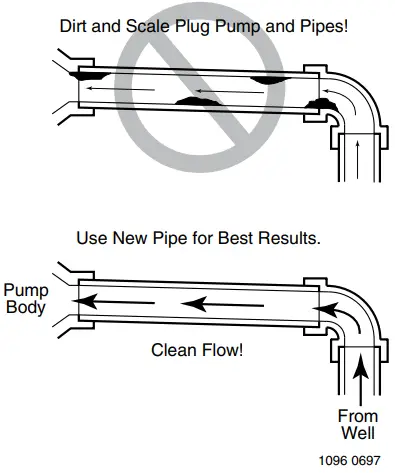 | 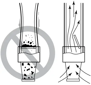 |
| Figure 1 – No Dirt or Scale in Suction Pipe | Figure 2 – Foot Valve Must Work Freely |
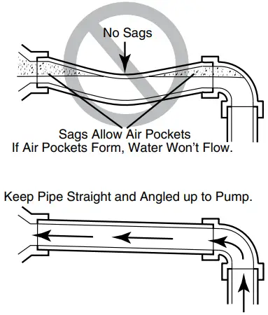 | 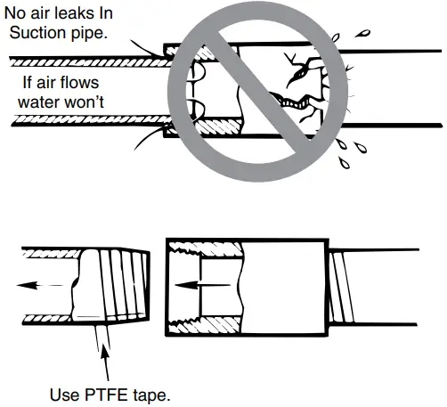 |
| Figure 3 – No Air Pockets in Suction Pipe | Figure 4 – Suction Pipe Must Not Leak |
NOTICE: Well must not be more than 20’ depth to water.
- Long runs and many fittings increase friction and reduce flow. Locate pump as close to well as possible: use as few elbows and fittings as possible.
- Be sure well is clear of sand. Sand will plug the pump and void the warranty.
- Protect pump and all piping from freezing.
Freezing will split pipe, damage pump and void the warranty. Check locally for frost protection requirements (usually pipe must be 12” below frost line and pump must be insulated). - Be sure all pipes and foot valve are clean and in good shape.
- No air pockets in suction pipe.
- No leaks in suction pipe. Use PTFE pipe thread sealant tape to seal pipe joints.
- Unions installed near pump and well will aid in servicing. Leave room to use wrenches.
 WARNING Pump body may explode if used as a booster pump. DO NOT use in a booster application.
PERFORMANCE CHART (in gallons per minute)
High Head
| Disch. Press PSI | PD2HD-L | PD2HE-L | PD2HF-L, PDSSHFT | PDHG-L | PDHHG-L | |||||||||||||
| Distance Above Water | ||||||||||||||||||
| 5′ | 10′ | 15′ | 20′ | 5′ | 10′ | 15′ | 20′ | 5′ | 10’15’20’ | 5′ | 10′ | 15′ | 20′ | 5′ | 10′ | 15′ | 20′ | |
| Capacity — Gallons Per Minute | ||||||||||||||||||
| 10 | 59 | 53 | 50 | 43 | 55 | 49 | 48 | 45 | 67 | 615646 | 69 | 67 | 65 | 62 | 92 | 83 | 81 | 78 |
| 15 | 52 | 50 | 45 | 41 | 51 | 46 | 45 | 44 | 66 | 585545 | 65 | 63 | 60 | 58 | 86 | 79 | 78 | 76 |
| 20 | 46 | 42 | 40 | 35 | 45 | 42 | 39 | 37 | 61 | 565444 | 59 | 56 | 54 | 52 | 80 | 76 | 75 | 74 |
| 25 | 38 | 33 | 31 | 26 | 38 | 35 | 32 | 29 | 55 | 525143 | 52 | 50 | 48 | 45 | 73 | 71 | 70 | 69 |
| 30 | 28 | 23 | 20 | 31 | 28 | 24 | 20 | 48 | 454438 | 47 | 45 | 42 | 40 | 66 | 66 | 65 | 64 | |
| 35 | 18 | 4 | 23 | 19 | 16 | 11 | 39 | 373428 | 42 | 38 | 35 | 32 | 60 | 60 | 59 | 58 | ||
| 40 | 17 | 13 | 8 | 33 | 272011 | 34 | 30 | 27 | 23 | 55 | 54 | 53 | 52 | |||||
| 45 | 18 | 14 8 | 25 | 17 | 10 | 47 | 46 | 46 | 45 | |||||||||
| 50 | 14 | 7 | 40 | 38 | 37 | 36 | ||||||||||||
All PD models except PDHG-L and PDHHG-L have discharge and suction size of 1-1/2” NPT. PDHG-L and PDHHG-L have 2” NPT suction and discharge.
All PD2 models have discharge size of 1-1/2”. Suction is 2” NPT.
Model PDSSHFT has 2” NPT suction and 1-1/2” NPT discharge.
Well Pipe Installation
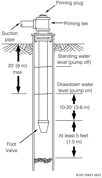 | 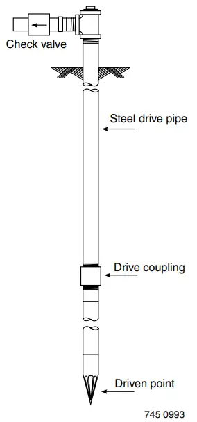 | 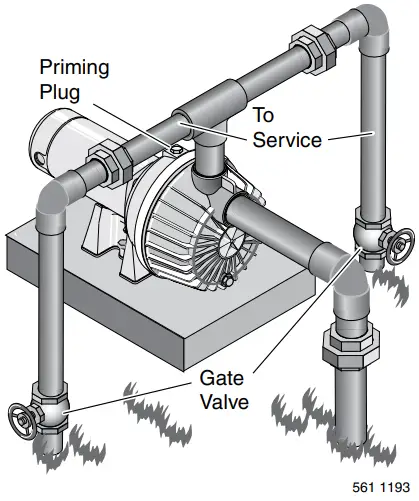 |
| Figure 5 – Cased/Dug Well Installation | Figure 6 – Driven Point Installation | Figure 7 – Multiple Discharge |
NOTICE: Use the installation method below which matches your well type.
CASED WELL INSTALLATION
- Inspect foot valve to be sure it works freely. Inspect strainer to be sure it is clean.
- Connect foot valve and strainer to the first length of suction pipe and lower pipe into well. Add sections of pipe as needed, using PTFE pipe thread sealant tape on male threads. Be sure that all suction pipe is leakproof or pump will lose prime and fail to pump. Install foot valve 10 to 20 feet below the lowest level to which water will drop while pump is operating (pumping water level). Your well driller can furnish this in formation.
- To prevent sand and sediment from entering the pumping system, the foot valve/strainer should be at least 5 feet above the bottom of the well.
- When the proper depth is reached, install a sanitary well seal over the pipe and in the well casing.
Tighten the bolts to seal the casing. - When using a foot valve, a priming tee and plug as shown in Figure 5 are recommended.
DUG WELL INSTALLATION
Same as cased well installation.
DRIVEN POINT INSTALLATION
- Connect the suction pipe to the drive point as illustrated in Figure 6. Keep horizontal pipe run as short as possible. Use PTFE pipe thread sealant tape on male pipe threads. Multiple well points may be necessary to provide sufficient water to pump.
- Install a check valve in horizontal pipe. Flow arrow on check valve must point toward pump.
HORIZONTAL PIPING FROM WELL TO PUMP
- Never install a suction pipe that is smaller than the suction port of the pump.
- To aid priming on well point installations, install a line check valve as shown in Figure 6. Be sure check valve flow arrow points toward pump.
DISCHARGE PIPE SIZES
- If increasing discharge pipe size, install reducer in pump discharge port. Do not increase pipe size by stages.
- When the pump is set away from the points of water use, the discharge pipe size should be increased to reduce pressure losses caused by friction.
• Up to 100’ run: Same size as pump discharge port.
• 100’ to 300’ run: Increase one pipe size.
• 300’ to 600’ run: Increase two pipe sizes.
LAWN SPRINKLING APPLICATION
This pump is designed for lawn sprinkling. It is de signed to deliver plenty of water at full sprinkler pressure. It can pump from a pond, cistern or well points.
Pump discharge can be divided to supply two (2) or more sprinkler systems. A suggested multiple discharge to service is shown in Figure 7.
Do not use in a pressure tank or booster pump application.
Pump/Piping Installation
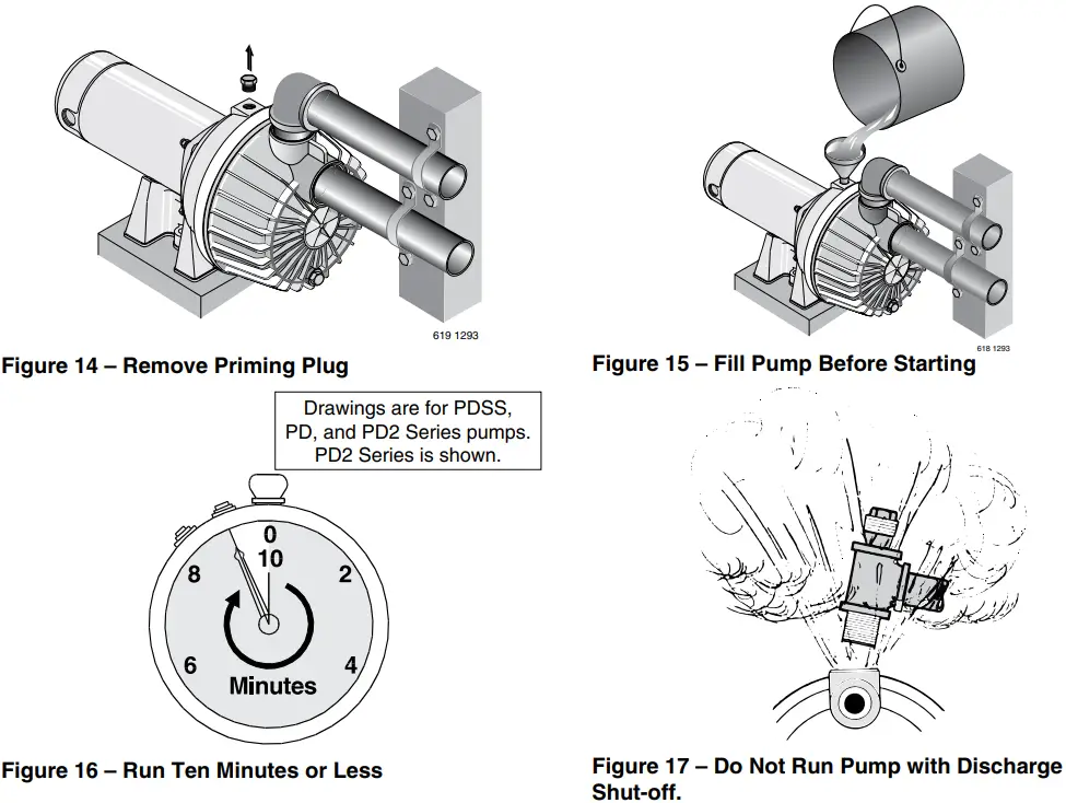
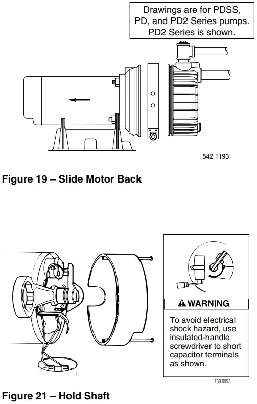
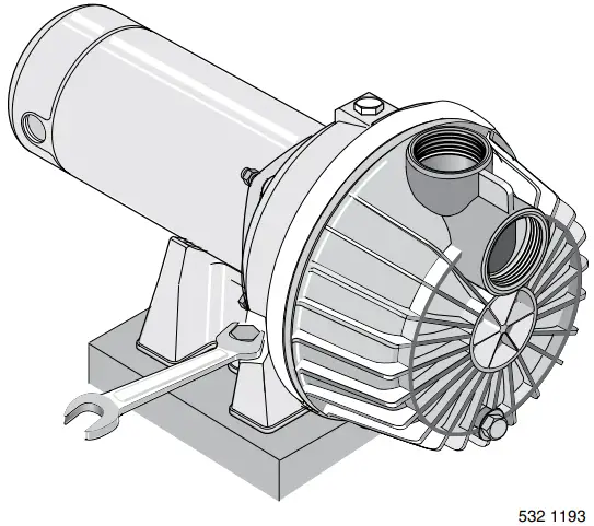 | Drawings are for PDSS, PD, and PD2 Series pumps. PD2 Series is shown.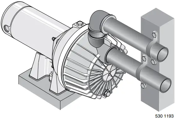 |
| Figure 8 – Bolt Pump Down | Figure 9 – Independently Support All Piping Attached to Pump |
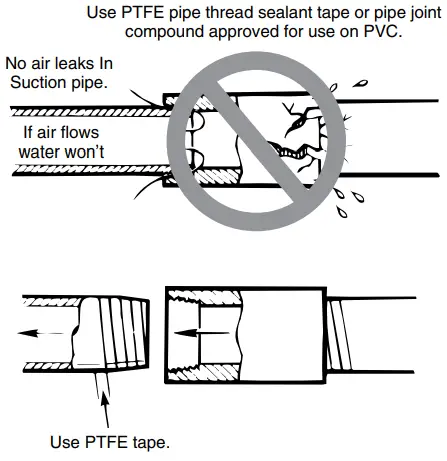 | 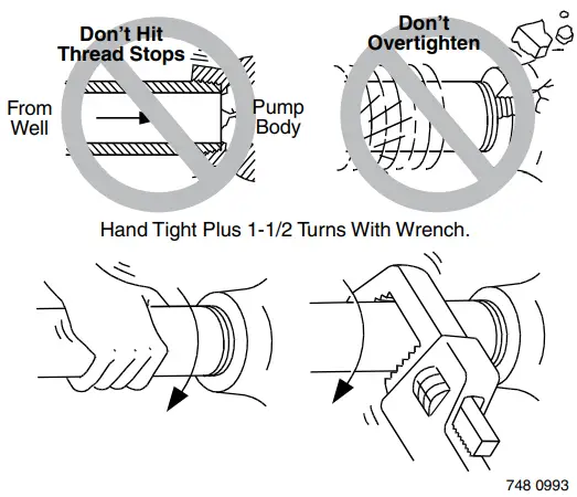 |
| Figure 10 – Use PTFE pipe thread sealant tape on pipe joints and connections to pump. | Figure 11 – Don’t overtighten. |
PUMP INSTALLATION
NOTICE: Use only PTFE pipe thread sealant tape for making all threaded connections to the pump itself. Do not use pipe joint compounds on plastic pumps: they can react with the plastic in the pump components. Make sure that all pipe joints in the suction pipe are air tight as well as water tight. If the suction pipe can suck air, the pump will not be able to pull water from the well.
- Bolt pump to solid, level foundation.
- Support all piping connected to the pump.
- Wrap 1-1/2 to two layers of PTFE pipe thread sealant tape clockwise (as you face end of pipe) on all male threads being attached to pump.
- Tighten joints hand tight plus 1-1/2 turns. Do not overtighten.
NOTICE: Install pump as close to well head as possible. Long piping runs and many fittings create friction and reduce flow.
NOTICE: For long horizontal pipe runs, install a priming tee between check valve and well head as shown in Figure 6. For driven point installations, install a check valve as shown in Figure 6. Be sure check valve flow arrow points toward pump.
Use schedule 80 or iron pipe. See “Well Pipe In stallation” for more information.
Electrical
THE MOTOR IS SET FOR 230 VOLTS WHEN SHIPPED.
To change the motor to use 115 volts:
- Turn off power
- Remove the back motor cover.
- Use a screwdriver or 1/2” wrench and turn the voltage selector dial counterclockwise until 115 shows in the dial opening.
- Reinstall the motor cover.
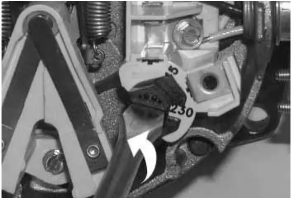 | 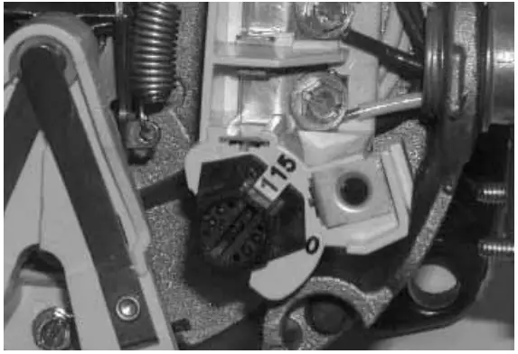 |
| Figure 12: Changing the Voltage Setting | Figure 13: Motor Set for 115 Volt Operation |
![]() WARNING Hazardous voltage. Can shock, burn, or cause death. Disconnect power to motor before working on pump or motor. Ground motor before connecting to power supply.
WARNING Hazardous voltage. Can shock, burn, or cause death. Disconnect power to motor before working on pump or motor. Ground motor before connecting to power supply.
WIRING![]() Ground motor before connecting to electrical power supply. Failure to ground motor can cause severe or fatal electrical shock hazard.
Ground motor before connecting to electrical power supply. Failure to ground motor can cause severe or fatal electrical shock hazard.![]() Do not ground to a gas supply line.
Do not ground to a gas supply line.![]() To avoid dangerous or fatal electrical shock, turn OFF power to motor before working on electrical connections.
To avoid dangerous or fatal electrical shock, turn OFF power to motor before working on electrical connections.![]() Supply voltage must be within ±10% of nameplate voltage. Incorrect voltage can cause fire or damage motor and voids warranty. If in doubt consult a licensed electrician.
Supply voltage must be within ±10% of nameplate voltage. Incorrect voltage can cause fire or damage motor and voids warranty. If in doubt consult a licensed electrician.![]() Use wire size specified in Wiring Chart (Page 7). If possible, connect pump to a separate branch circuit with no other appliances on it.
Use wire size specified in Wiring Chart (Page 7). If possible, connect pump to a separate branch circuit with no other appliances on it.![]() Wire motor according to diagram on motor nameplate. If nameplate diagram differs from diagrams above, follow nameplate diagram.
Wire motor according to diagram on motor nameplate. If nameplate diagram differs from diagrams above, follow nameplate diagram.
- Install, ground, wire and maintain this pump in accordance with electrical code requirements.
Consult your local building inspector for information about codes. - Provide a correctly fused disconnect switch for protection while working on motor. Consult local or national electrical codes for switch requirements.
- Disconnect power before servicing motor or pump.
If the disconnect switch is out of sight of pump, lock it open and tag it to prevent unexpected power application. - Ground the pump permanently using a wire of the same size as that specified in wiring chart (Page 7).
Make ground connection to green grounding terminal under motor canopy marked GRD. or
- Connect ground wire to a grounded lead in the service panel or to a metal underground water pipe or well casing at least 10 feet long. Do not connect to plastic pipe or insulated fittings.
- Protect current carrying and grounding conductors from cuts, grease, heat, oil, and chemicals.
- Connect current carrying conductors to terminals L1 and L2 under motor canopy. When replacing motor, check wiring diagram on motor nameplate against Figures 12-13. If the motor wiring diagram does not match either diagram in Figures 12-13, follow the dia gram on the motor.
IMPORTANT: 115/230 Volt single phase models are shipped from factory with motor wired for 230 volts. If power supply is 115 volts, remove motor canopy and reconnect motor as shown in Figures 12-13. Do not try to run motor as received on 115 volt current. - Motor has automatic internal thermal overload protection. If motor has stopped for unknown reasons, thermal overload may restart it unexpectedly, which could cause injury or property damage. Disconnect power before servicing motor.
- If this procedure or the wiring diagrams are confusing, consult a licensed electrician.
WIRING CHART (Recommended Wire and Fuse Sizes)
| Pump Model | HP | Volt | Max. Load Amps | Branch Fuse* Rating* Amps | DISTANCE IN FEET FROM MOTOR TO METER | |||||||
| 0 – 50 | 51 – 100 | 101 – 200 | 1 201 – 300 | 301 – 400 | 401 – 500 | |||||||
| WIRE SIZE (AWG) | ||||||||||||
| PDHG-L | 2 | 115/230 | 24.0/12.0 | 30/15 | 10/14 | 10/14 | 8/14 | 6/12 | 4/10 | 4/10 | ||
| PDHHG-L | 2-1/2 | 115/230 | 26.0/13.0 | 30/15 | 10/14 | 10/14 | 8/14 | 6/12 | 4/10 | 4/10 | ||
| PD2HD-L | 3/4 | 115/230 | 14.8/7.4 | 20/15 | 12/14 | 12/14 | 8/14 | 6/14 | 6/12 | 4/10 | ||
| PD2HE-L | 1 | 115/230 | 14.8/7.4 | 20/15 | 12/14 | 12/14 | 8/14 | 6/14 | 6/12 | 4/10 | ||
| PD2HF-L | 1-1/2 | 115/230 | 19.2/9.6 | 25/15 | 10/14 | 10/14 | 8/14 | 6/12 | 4/10 | 4/10 | ||
| PDSSHFT | 1-1/2 | 115/230 | 18.0/9.0 | 25/15 | 10/14 | 10/14 | 8/14 | 6/12 | 6/12 | 4/10 | ||
(*) Dual element or Fusetron time delay fuses recommended for all motor circuits.
Operation
PRIMING THE PUMP
NOTICE: ‘Priming’ refers to the pump expelling all air in the system and beginning to move water from its source out into the system. It does not refer only to pouring water into the pump (although pouring water in is usually the first step).
NOTICE: NEVER run pump dry. Running pump without water in it will damage seals and can melt impeller and diffuser. To prevent damage, fill pump with water before starting.
- Remove priming plug (Figure 14).
- Make sure suction and discharge valves and any hoses on discharge side of pump are open.
- Fill pump and suction pipe with water.
- Replace priming plug, using PTFE pipe thread sealant tape on thread; tighten plug.
NOTICE: If a priming tee and plug have been provided for a long horizontal run, be sure to fill suction pipe through this tee and replace plug.
(Don’t forget to seal the plug with PTFE tape.) - Start pump: water should be produced in 10 minutes or less, the time depending on depth to water (not more than 20’) and length of horizontal run (10’ of horizontal suction pipe = 1’ of vertical lift due to friction losses in the pipe).
If no water is produced within 10 minutes, stop pump, release all pressure, remove priming plug, refill and try again.![]() WARNING Hazardous pressure and risk of explosion and scalding. If pump is run continu ously at no flow (that is, with discharge shut off or without priming), water may boil in pump and piping system. Under steam pressure, pipes may rupture, blow off of fittings or blow out of pump ports and scald anyone near.
WARNING Hazardous pressure and risk of explosion and scalding. If pump is run continu ously at no flow (that is, with discharge shut off or without priming), water may boil in pump and piping system. Under steam pressure, pipes may rupture, blow off of fittings or blow out of pump ports and scald anyone near.
To prevent explosion, do the following:
A. Be sure discharge (valve, pistol grip hose nozzle, etc.) is open whenever pump is running.
B. If pump fails to produce water when attempting to prime, release all pressure, drain pump and refill with cold water after every two attempts.
C. When priming, monitor pump and piping temperature. If pump or piping begin to feel warm to the touch, shut off pump and allow system to cool off. Release all pressure in system and refill pump and piping with cold water.
Maintenance
 |  |
MAINTENANCE
Pump and piping need not be disconnected to repair or replace motor or seal (see Figure 19). If motor is replaced, replace the shaft seal. Keep one on hand for future use.
Be sure to prime pump before starting.
NOTICE: Check motor label for lubrication instructions.
The mechanical shaft seal in the pump is water lubricated and self-adjusting.
NOTICE: Drain pump when disconnecting from service or when it might freeze.
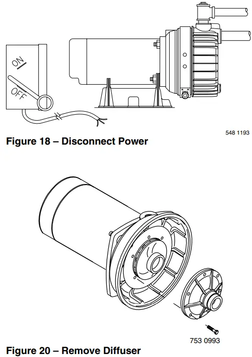
PUMP DISASSEMBLY
- Disconnect power to motor.
NOTICE: Mark wires for correct assembly. - Remove clamp (see Figure 19).
- Remove pump base mounting bolts. Motor assembly and back half of pump can now be pulled away from pump front half (Figure 19). CAREFULLY remove O-ring.
CLEANING/REPLACING IMPELLER
NOTICE: First, follow instructions under “Pump Disassembly”.
- Remove four screws fastening diffuser to seal plate; remove diffuser (see Figure 20). Exposed impeller can now be cleaned.
- If impeller must be replaced, loosen two machine screws and remove motor canopy (see Figure 21).
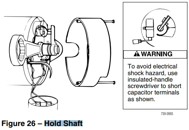
- WARNING Capacitor voltage may be hazardous. To discharge capacitor, hold insulated handle screwdriver BY THE HANDLE and short capacitor terminals together (see Figure 21). Do not touch metal screwdriver blade or capacitor terminals. If in doubt, consult a qualified electrician.
- Unscrew capacitor clamp and remove capacitor. Do not disconnect capacitor wires to motor.
- Slide 7/16” open end wrench in behind spring loaded switch on motor end of shaft; hold motor shaft with wrench on shaft flats and unscrew impeller by turning counterclockwise when looking into eye of impeller.
- To reinstall, reverse steps 1 through 5.
- See directions under “Pump Reassembly,” Page 11.
 |  |
 |  |
REMOVING OLD SEAL
- Follow instructions under “Pump Disassembly”.
- Follow steps 2 through 5 under “Cleaning/Replacing Impeller”.
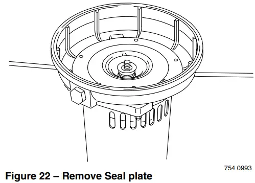
- Unscrew four nuts holding pump back half to motor. Remove rotating half of seal by placing two screwdrivers under back half of pump body and carefully prying up (Figure 22). Back half of pump body will slide off shaft, bringing seal with it.
NOTICE: Be sure you do not scratch or mar shaft; if shaft is marred, it must be dressed smooth with fine emery or crocus cloth before installing new seal.
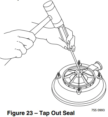
DO NOT reduce shaft diameter! - Place pump body half face down on flat surface and tap out stationary half of seal (see Figure 23).
INSTALLING NEW SEAL
- Clean seal cavity in seal plate.
- Wet outer edge of Rubber Cup on ceramic seat with liquid soap. Be sparing!
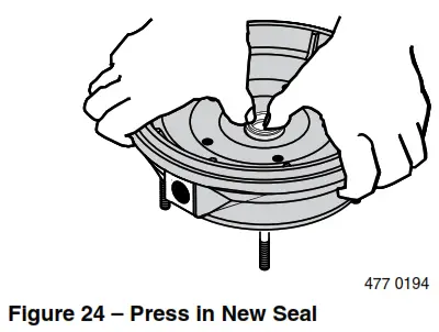
- Put clean cardboard washer on seal face. With thumb pressure, press ceramic seal half firmly and squarely into seal cavity (See Figure 24). Polished face of ceramic seat is up. If seal will not seat correctly, remove, placing seal face up on bench.
Reclean cavity. Seal should now seat correctly. - If seal does not seat correctly after recleaning cavity, place a cardboard washer over polished seal face and carefully press into place using a piece of standard 3/4” pipe as a press.
NOTICE: Be sure you do not scratch seal face. - Dispose of cardboard washer and recheck seal face to be sure it is free of dirt, foreign particles, scratches and grease.
- Inspect shaft to be sure it is free of nicks and scratches.
- Reassemble pump body half to motor flange. BE SURE it is right side up.
- Apply liquid soap sparingly (one drop is sufficient) to inside diameter of rotating seal member.
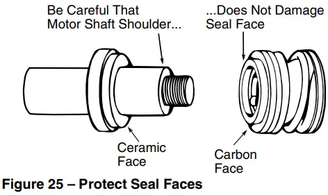
- Slide rotating seal member (carbon face first) onto shaft until rubber drive ring hits shaft shoulder.
NOTICE: Be sure not to nick or scratch carbon face of seal when passing it over threaded shaft end or shaft shoulder. The carbon surface must remain clean or short seal life will result.

- Hold motor shaft with 7/16” open end wrench on shaft flats and screw impeller onto shaft. Be sure you do not touch capacitor terminals with body or any metal object. Tightening impeller will automatically locate seal in correct position.
- Remount diffuser on pump body half with five screws.
- Follow instructions under “Pump Reassembly”.
PUMP REASSEMBLY
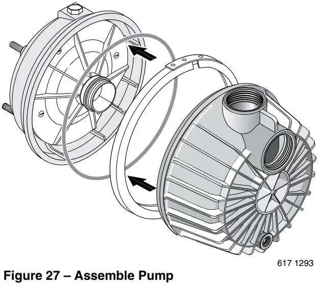
- Clean O-ring and O-ring groove.
- Put O-ring in groove on face of flange; put pump halves together (see Figure 27).
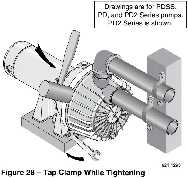
- BE SURE inside of clamp is clean. Place clamp on pump halves; snug up. Alternately tighten screw and tap clamp with mallet to seat O-ring (see Figure 28).
- Replace base mounting bolts.
- Replace pressure switch tubing and motor wiring; close draincock.
- Prime pump according to instructions. See “Operation.”
- Check for leaks.
CORROSION RESISTANT CENTRIFUGAL PUMPS
MODELS PDHGL, and PDHHGL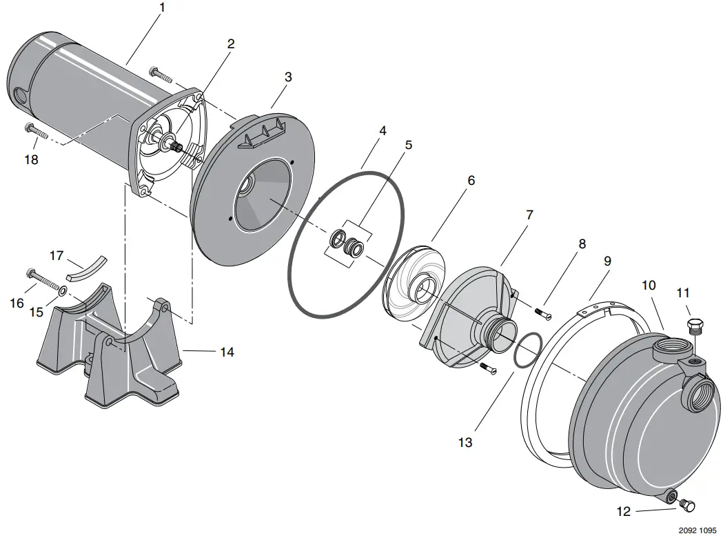
| Key No. | Part Description | PDHGL 230V 60 Hz/1 Ph 2 HP | PDHHGL 230V 60 Hz/1 Ph 21/2 HP |
| 1 | Motor | J218-883APKG | J218-628APKG |
| 2 | Slinger | 17351-0009 | 17351-0009 |
| 3 | Tank Body Back Half | C3-189P1 | C3-189P1 |
| 4 | O Ring | U9-228A | U9-228A |
| 5 | Shaft Seal for 5/8” Shaft | U109-6A | U109-6A |
| 6 | Impeller | C105-214PFA | C105-214PGA |
| • | Impeller screw | C30-51SS | C30-51SS |
| 7 | Diffuser | C1-274P | C1-274P |
| 8 | Screw – #8 – 32 RH | U30-542SS(2) | U30-542SS(2) |
| 9 | “V” Clamp | C19-37A | C19-37A |
| 10 | Tank Body Front Half (Complete) (Includes Key Nos. 12 and 13) | C176-62P | C176-62P |
| 11 | Priming Plug | WC78-39T | WC78-39T |
| 12 | Drain Plug – 1/4 NPT | WC78-40T | WC78-40T |
| 13 | O Ring | U9-393 | U9-393 |
| 14 | Base | C4-42P | C4-41P |
| 15 | Washer – 5/16 | U43-42SS(2) | U43-42SS(2) |
| 16 | Capscrew | U30-77SS(2) | U30-104ZP(2) |
| 17 | Rubber Pad | C35-11 | C35-15 |
| 18 | Capscrew | U30-74SS(2) | U30-104ZP(2) |
| • | Owner’s Manual | S156 | S156 |
• Not illustrated
NOTICE: Quantity is one unless otherwise noted ( ).
CORROSION RESISTANT CENTRIFUGAL PUMPS
MODELS PD2HDL, PD2HEL, PD2HFL, and PDSSHFT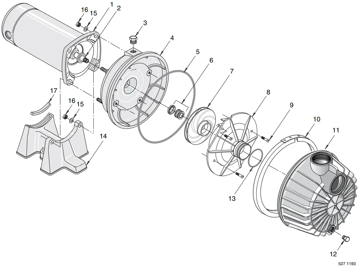
| Key No. | Part Description | PD2HDL 115/230V 60 Hz/1 Ph 3/4 HP | PD2HEL 115/230V 60 Hz/1 Ph 1 HP | PD2HFL 115/230V 60 Hz/1 Ph 11/2 HP | PDSSHFT 115/230V 60 Hz/1 Ph 11/2 HP |
| 1 | Motor* | J218-596PKG | J218-596PKG | J218-601PKG | A100FL-T |
| 2 | Slinger | 17351-0009 | 17351-0009 | 17351-0009 | 17351-0009 |
| 3 | Priming Plug | WC78-39T | WC78-39T | WC78-39T | WC78-39T |
| 4 | Tank Body Back Half (Complete) | L176-47P1 | L176-47P1 | L176-47P1 | L176-47P2SS |
| 5 | O Ring | U9-399 | U9-399 | U9-399 | U9-399 |
| 6 | Shaft Seal for 5/8” Shaft | U109-6A | U109-6A | U109-6A | U109-6A |
| 7 | Impeller | C105-92PVC | C105-92PVB | C105-92PBBB | C105-92PBS |
| 8 | Diffuser | C1-258PC | C1-258PCA | C1-258PCA | C1-258PCAEB |
| 9 | Screw – #8 – 32 RH | U30-997SS | U30-997SS | U30-869SS (4) | U30-869SS (4) |
| • | #8 Lockwasher | — | — | U43-21SS(4) | U43-21SS(4) |
| 10 | “V” Clamp | C19-54SS | C19-54SS | C19-54SS | C19-54SS |
| 11 | Tank Body Front Half (Complete) | C176-66P | C176-66P | C176-66P | C176-66P |
| 12 | Drain Plug – 1/4 NPT | WC78-40T | WC78-40T | WC78-40T | WC78-40T |
| 13 | O Ring | U9-226 | U9-226 | U9-226 | U9-226 |
| 14 | Base | C4-42P | C4-42P | C4-42P | C4-41P |
| 15 | Washer – 5/16 | U43-11ZP(4) | U43-11ZP(4) | U43-11ZP(4) | U43-11SS(4) |
| 16 | Nut – 5/16 – 18 | U36-37ZP(4) | U36-37ZP(4) | U36-37ZP(4) | U36-37SS(4) |
| 17 | Rubber Pad | C35-11 | C35-11 | C35-11 | C35-15 |
| • | Owner’s Manual | S156 | S156 | S156 | S156 |
• Not illustrated.
* Model PDSSHFT uses TEFC motor.
NOTICE: Quantity is one unless otherwise noted ( ).
Troubleshooting Chart
| SYMPTOM | POSSIBLE CAUSE(S) | CORRECTIVE ACTION |
| Motor will not run | Disconnect switch is off Fuse is blown Starting switch is defective Wires at motor are loose, disconnected, or wired incorrectly | Be sure switch is on Replace fuse Replace starting switch Refer to instructions on wiring. Check and tighten all wiring. Capacitor voltage may be hazardous. To discharge capacitor, hold insulated handle screwdriver BY THE HANDLE and short capacitor terminals together. Do not touch metal screwdriver blade or capacitor terminals. If in doubt, consult a qualified electrician. |
| Motor runs hot and overload kicks off | Motor is wired incorrectly Voltage is too low | Refer to instructions on wiring Check with power company. Install heavier wiring if wire size is too small (See Electrical, Page 6) |
| Motor runs but no water is delivered *(Notice: Check prime before looking for other causes. Unscrew priming plug and see if there is water in priming hole.) | *Pump in new installation did not pick up prime through: 1. Improper priming 2. Air leaks 3. Leaking foot valve *Pump has lost prime through: 1. Air leaks 2. Water level below suction of pump Impeller is plugged Check valve or foot valve is stuck in closed position Pipes are frozen Foot valve and/or strainer are buried in sand or mud | In new installation: 1. Re-prime according to instructions 2. Check all connections on suction line 3. Replace foot valve In installation already in use: 1. Check all connections on suction line and shaft seal 2. Lower suction line into water and re-prime. If receding water level in well exceeds suction lift, a deep well pump is needed Clean impeller; see Maintenance Replace check valve or foot valve Thaw pipes. Bury pipes below frost line. Heat pit or pump house. Raise foot valve and/or strainer above well bottom |
| Pump does not deliver water to full capacity (Also check point 3 immediately above) | Water level in well is lower than estimated Steel piping (if used) is corroded or limed, causing excess friction Offset piping is too small in size | A deep well jet pump may be needed (over 20 ft. to water) Replace with plastic pipe where possible, otherwise with new steel pipe Use larger offset piping |
| Pump leaks around clamp | Clamp loose | STOP PUMP, tighten clamp nut 1-2 turns. Alternately tighten and tap on clamp with mallet to seat O-Ring. Do not overtighten. |
Limited Warranty
STA-RITE warrants to the original consumer purchaser (“Purchaser” or “You”) of the products listed below, that they will be free from defects in material and workmanship for the Warranty Period shown below.
| Product | Warranty Period |
| Water Systems Products — jet pumps, small centrifugal pumps, submersible pumps and related accessories | whichever occurs first: 12 months from date of original installation, or 18 months from date of manufacture |
| Pro-Source™ Composite Tanks | 5 years from date of original installation |
| Pro-Source™ Steel Pressure Tanks | 5 years from date of original installation |
| Pro-Source™ Epoxy-Lined Tanks | 3 years from date of original installation |
| Sump/Sewage/Effluent Products | 12 months from date of original installation, or 18 months from date of manufacture |
Our warranty will not apply to any product that, in our sole judgement, has been subject to negligence, misapplication, improper installation, or improper maintenance. Without limiting the foregoing, operating a three phase motor with single phase power through a phase converter will void the warranty. Note also that three phase motors must be protected by three-leg, ambient compensated, extra-quick trip overload relays of the recommended size or the warranty is void.
Your only remedy, and STA-RITE’s only duty, is that STA-RITE repair or replace defective products (at STA-RITE’s choice). You must pay all labor and shipping charges associated with this warranty and must request warranty service through the installing dealer as soon as a problem is discovered. No request for service will be accepted if received after the Warranty Period has expired. This warranty is not transferable.
STA-RITE SHALL NOT BE LIABLE FOR ANY CONSEQUENTIAL, INCIDENTAL, OR CONTINGENT DAMAGES WHATSOEVER.
THE FOREGOING WARRANTIES ARE EXCLUSIVE AND IN LIEU OF ALL OTHER EXPRESS AND IMPLIED WARRANTIES, INCLUDING BUT NOT LIMITED TO THE IMPLIED WARRANTIES OF MERCHANTABILITY AND FITNESS FOR A PARTICULAR PURPOSE. THE FOREGOING WARRANTIES SHALL NOT EXTEND BEYOND THE DURATION EXPRESSLY PROVIDED HEREIN.
Some states do not allow the exclusion or limitation of incidental or consequential damages or limitations on the duration of an implied warranty, so the above limitations or exclusions may not apply to You. This warranty gives You specific legal rights and You may also have other rights which vary from state to state.
This Limited Warranty is effective June 1, 2011 and replaces all undated warranties and warranties dated before June 1, 2011.
STA-RITE INDUSTRIES
293 Wright Street • Delavan, WI U.S.A. 53115
Phone: 1-888-782-7483 • Fax: 1-800-426-9446 • Web Site: sta-rite.com
293 WRIGHT STREET, DELAVAN, WI 53115
WWW.STA-RITE.COM
PH: 888-782-7483
© 2012 Pentair, Inc. All Rights Reserved.
S156 (11/07/12)


