
GPSMAP®8X10/8X12/8X16
INSTALLATION
INSTRUCTIONS
Important Safety Information
![]() WARNING
WARNING
Failure to follow these warnings cautions, and notices could result in personal injury, damage to the vessel or device, or poor product performance.
See the Important Safety and Product Information guide in the product box for product warnings and other important information.
When connecting the power cable, do not remove the in-line fuse holder. To prevent the possibility of injury or product damage caused by fire or overheating, the appropriate fuse must be in place as indicated in the product specifications. In addition, connecting the power cable without the appropriate fuse in place voids the product warranty.![]() CAUTION
CAUTION
To avoid possible personal injury, always wear safety goggles, ear protection, and a dust mask when drilling, cutting, or sanding.
To avoid possible personal injury or damage to the device and vessel, disconnect the vessel’s power supply before beginning to install the device.
To avoid possible personal injury or damage to the device or vessel, before applying power to the device, make sure that it has been properly grounded, following the instructions in the guide.
NOTICE
For the best possible performance, the device must be installed according to these instructions.
When drilling or cutting, always check what is on the opposite side of the surface to avoid damaging the vessel.
Read all installation instructions before proceeding with the installation. If you experience difficulty during the installation, contact Garmin®Product Support.
Contacting Garmin Support
- Go to support.garmin.com for help and information, such as product manuals, frequently asked questions, videos, and customer support.
- In the USA, call 913-397-8200 or 1-800-800-1020.
- In the UK, call 0808 238 0000.
- In Europe, call +44 (0) 870 850 1241.
Software Update
You may need to update the Chartplotter software after installation. For the instructions on how to update the software,see the owner’s manual at garmin.com/manuals/GPSMAP84xx -86xx.
Tools Needed
- Drill and drill bits
3.0 mm (1/8 in.) drill bit for bail mounting
6 mm (9/16 in.) drill bit for flush mounting
2 mm (1/8 in.) drill bit for flush mounting using wood screws
6 mm (9/64 in.) drill bit for flush mounting using the nut plate
6.0 mm (1/4 in.) drill bit for flush mounting using the nut plate - #2 Phillips screwdriver
- Jigsaw or rotary tool
- File and sandpaper
- Marine-grade sealant, approved for use on plastics (recommended)
Mounting Considerations
NOTICE
This device should be mounted in a location that is not exposed to extreme temperatures or conditions. The temperature range for this device is listed in the product specifications. Extended exposure to temperatures exceeding the specified temperature range, in storage or operating conditions, may cause device failure. Extreme-temperature-induced damage and related consequences are not covered by the warranty. You can flush mount the device in the dashboard, or bail mounts the device on the dashboard.
When selecting a mounting location, observe these considerations.
- You should mount the device to provide an optimal viewing angle as you operate your boat.
- You must select a location that is strong enough to support the weight of the device and protect it from excessive vibration or shock.
- To avoid interference with a magnetic compass, you must not mount the device closer to a compass than the compass-safe distance value listed in the product specifications.
- You must select a location that allows room for the routing and connection of all cables.
- You should select a location that allows for easy access to the device touchscreen.
- You should select a location that allows for access to the microSD® card in the back of the device. If the location does not allow access, you must insert the memory cards before installing the device.
Bail Mounting the Device
NOTICE
If you are mounting the bracket on fiberglass with screws, it is recommended to use a countersink bit to drill a clearance counterbore through only the top gel-coat layer. This will help to avoid cracking in the gel-coat layer when the screws are tightened.
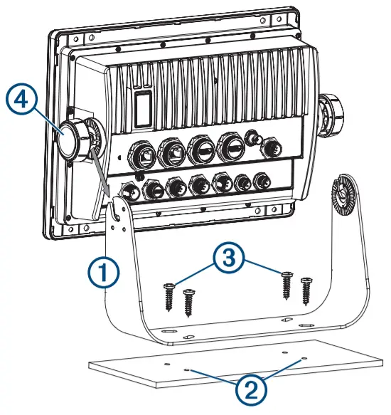
You can use the bracket to bail mount the device on a flat surface. The bail-mount bracket and hardware are included in 8×10 and 8×12 models. The ball amount is available for purchase as an accessory for the 8×16 models.
- Using the bail-mount bracket as a template, mark the pilot holes.

- Using a 3 mm (1/8 in.) drill bit, drill the pilot holes.
- Secure the bail-mount bracket to the surface using the included washers and wood screws.
- Install the bail-mount knobs on the sides of the device.
- Place the device in the bail-mount bracket, and tighten the bail-mount knobs.
- Install the trim caps by snapping them in place around the edges of the device.
Mounting the Device
NOTICE
Be careful when cutting the hole to flush mount the device.
There is only a small amount of clearance between the case and the mounting holes, and cutting the hole too large could compromise the stability of the device after it is mounted.
Use only the included hardware when mounting this device.
Using mounting hardware not provided with the device may damage the device.
To avoid potential damage to the powder coating, use only the included screws to mount the device. Using screws other than the ones included will void your warranty.
Do not remove the blue, rubber protective bumper until after the installation is complete. The bumper helps protect the device from damage during installation.
If you will not have access to be back of the device and the microSD memory card slots after installations, you should install the microSD memory card prior to installation.
The included template and hardware can be used to flush mount the device in your dashboard. There are three options for hardware based on the mounting surface material.
- You can drill pilot holes and use the included wood screws.
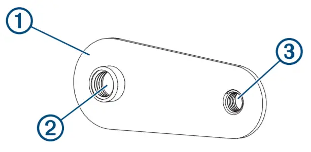
- You can drill holes and use the included nut plates and machine screws. The nut plates can add stability to a thinner surface.
- You can drill holes, tap them to M4, and use the included machine screws.
- Trim the template and make sure it fits in the location where you want to mount the device.
- Secure the template to the selected location.
- Using a 14.6 mm (/16 in.) drill bit, drill one or more of the holes inside the corners of the solid line on the template to prepare the mounting surface for cutting.
- Using a jigsaw or rotary tool, cut the mounting surface along the inside of the solid line on the template.
- Place the device in the cutout to test the fit.
- If necessary, use a file and sandpaper to refine the size of the cutout.
- After the device fits correctly in the cutout, ensure the mounting holes on the device line up with the larger 6 mm(¼ in.) holes on the template
- If the mounting holes on the device do not line up, mark the new hole locations.
- Based on your mounting surface, drill or punch and tap the larger holes:
• Drill 3.2 mm (1/8 in.) pilot holes for the included woodscrews, and skip to step 18.1
• Drill 6 mm (¼ in.) holes for the included nut plate and machine screws.
• Drill and tap M4 holes for the included machine screws, and skip to step 18. - If using the nut plates, starting in one corner of the template, place a nut plate over the larger hole drilled in step 9.
 The smaller hole on the nut plate should line up with the smaller 3.6 mm (9/64 in.) hole on the template.
 - If the smaller hole on the nut plate does not line up with the smaller hole on the template, mark the new hole location.
- Repeat steps 10 and 11 for each nut plate.
- Using a 3.6 mm (9/64 in.) drill bit, drill the smaller holes.
- Remove the template from the mounting surface.
- Starting in one corner of the mounting location, place a nut plate on the back of the mounting surface, lining up the large and small holes.
The raised portion of the nut plate should fit into the larger whole.
- Secure the nut plate to the mounting surface by fastening an included M3 screw through the smaller 3.6 mm (/64 in.) hole.9
- Repeat steps 15 and 16 for each of the nut plates along the top and bottom of the device.
- Install the foam gasket on the back of the device.
The pieces of the foam gasket have adhesive on the back.
Make sure you remove the protective liner before installing them on the device. - If you will not have access to the back of the device after you mount it, connect all necessary cables and install microSD cards in the back of the device before placing it into the cutout.
NOTE: To prevent corrosion of the metal contacts, cover unused connectors with the attached weather caps. - Apply marine sealant between the mounting surface and the device to properly seal and prevent leakage behind the dashboard.
- If you will have access to the back of the device, apply marine sealant around the cutout.
- Place the device into the cutout.
- Secure the device to the mounting surface using the included M4 screws or wood screws, depending on the mounting method.
- Carefully remove and discard the rubber protective bumper.
- Wipe away all excess marine sealant.
- Install the trim caps by snapping them in place around the edges of the device.
 The smaller hole on the nut plate should line up with the smaller 3.6 mm (9/64 in.) hole on the template.
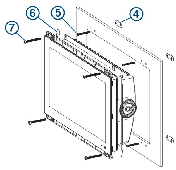
Connection Considerations
When connecting this device to power and to other Garmin devices, you should observe these considerations.
- The power and ground connections to the battery must be checked to make sure they are secured and cannot become loose.
- The cables may be packaged without the locking rings installed. The cables should be routed before the locking rings are installed.
- After installing a locking ring on a cable, you should make sure the ring is securely connected and the o-ring is in place so the power or data connection remains secure.
Connecting to Power
![]() WARNING
WARNING
When connecting the power cable, do not remove the in-line fuse holder. To prevent the possibility of injury or product damage caused by fire or overheating, the appropriate fuse must be in place as indicated in the product specifications. In addition, connecting the power cable without the appropriate fuse in place voids the product warranty.
You should connect the red wire to the same battery through the ignition or another manual switch to turn the device on and off.
- Route the power cable between the power source and the device.
- Connect the red power wire to the ignition or another manual switch, and connect the switch to the positive (+) battery terminal if necessary.
- Connect the black wire to the negative (-) battery terminal or to the ground.
- Connect the power cable to the device, and turn the locking ring clockwise to tighten it.
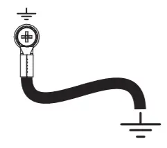
Additional Grounding Consideration
This device should not need additional chassis grounding in most installation situations. If you experience interference, you can use the grounding screw on the housing to connect the device to the water ground of the boat to help avoid the interference.
Power Cable Extensions
If necessary, the power cable can be extended using the appropriate wire gauge for the length of the extension.
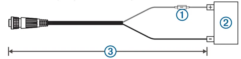
| Item | Description |
| 1 | Fuse |
| 2 | Battery |
| 3 | 6 ft. (1.8 m) no extension |
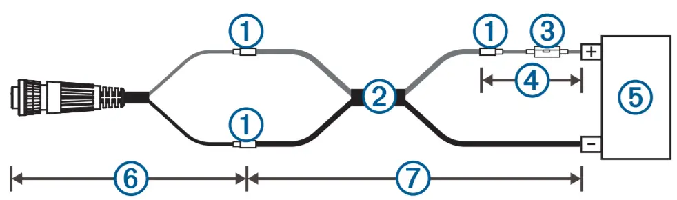
| Item | Description |
| 1 | Splice |
| 2 | • 10 AWG (5.26 mm²) extension wire, up to 15 ft. (4.6 m) • 8 AWG (8.36 mm²) extension wire, up to 23 ft. (7 m) • 6 AWG (13.29 mm²) extension wire, up to 36 ft. (11 m) |
| 3 | Fuse |
| 4 | 8 in. (20.3 cm) |
| 5 | Battery |
| 6 | 8 in. (20.3 cm) |
| 7 | 36 ft. (11 m) maximum extension |
Garmin Marine Network Considerations
NOTICE
A Garmin Marine Network PoE Isolation Coupler (010-10580-10) must be used when connecting any third-party device, such as a FLIR ® camera, to a Garmin Marine Network. Connecting a Power over Ethernet (PoE) device directly to a Garmin Marine Network Chartplotter damages the Garmin
Chartplotter and may damage the PoE device. Connecting any third-party device directly to a Garmin Marine Network Chartplotter will cause abnormal behavior on the Garmin devices, including the devices not properly turning off or the software, becoming inoperable.
This device can connect to additional Garmin Marine Network devices to share data such as radar, sonar, and detailed mapping. When connecting Garmin Marine Network devices to this device, observe these considerations.
- All devices connected to the Garmin Marine Network must be connected to the same ground. If multiple power sources are used for Garmin Marine Network devices, you must tie all ground connections from all power supply together using a low resistance connection or tie them to a common ground bus bar, if available.
- A Garmin Marine Network cable must be used for all Garmin Marine Network connections.
◦ Third-party CAT5 cable and RJ45 connectors must not be used for Garmin Marine Network connections.
◦ Additional Garmin Marine Network cables and connectors are available from your Garmin dealer. - The NETWORK ports on the device each act as a network switch. Any compatible device can be connected to any NETWORK port to share data with all devices on the boat connected by a Garmin Marine Network cable.
Station Connection Considerations
This device can be set up in conjunction with other compatible Garmin devices to work together as a station. When planning stations on your boat, observe these considerations.
- Devices earlier than the GPSMAP 8000 series and GPSMAP
8500 series cannot be used in a station. - Although it is not necessary, it is recommended that you install all of the devices you plan to use in one station near each other.
- No special connections are necessary to create a station, as long as all of the devices are connected to the Garmin Marine Network (Garmin Marine Network Considerations, page 3).
- Stations are created and modified using the device software.
See the owner’s manual provided with the device for more information.
NMEA 2000® Considerations
NOTICE
If you are connecting to an existing NMEA 2000 network, identify the NMEA 2000 power cable. Only one NMEA 2000 power cable is required for the NMEA 2000 network to operate properly.
An NMEA 2000 Power Isolator (010-11580-00) should be used in installations where the existing NMEA 2000 network manufacturer is unknown.
If you are installing an NMEA 2000 power cable, you must connect it to the boat ignition switch or through another in-line switch. NMEA 2000 devices will drain your battery if the NMEA 2000 power cable is connected to the battery directly.
This device can connect to an NMEA 2000 network on your boat to share data from NMEA 2000 compatible devices such as a GPS antenna or a VHF radio. The included NMEA 2000 cables and connectors allow you to connect the device to your existing NMEA 2000 network. If you do not have an existing NMEA 2000 network you can create a basic one using cables from Garmin.
If you are unfamiliar with NMEA 2000, you should read the Technical Reference for NMEA 2000 Products at garmin.com/manuals/nmea_2000.
The port labeled NMEA 2000 is used to connect the device to a standard NMEA 2000 network.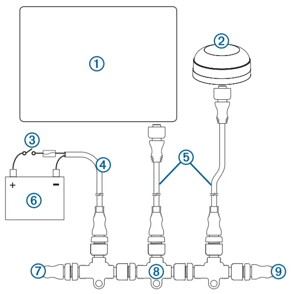
Item | Description |
| 1 | NMEA 2000 compatible Garmin device |
| 2 | GPS antenna |
| 3 | Ignition or in-line switch |
| 4 | NMEA 2000 power cable |
| 5 | NMEA 2000 drop cable |
| 6 | 12 Vdc power source |
| 7 | NMEA 2000 terminator or backbone cable |
| 8 | NMEA 2000 T-connector |
| 9 | NMEA 2000 terminator or backbone cable |
J1939 Engine Network Connection Considerations
NOTICE
You must use a Garmin GPSMAP J1939 accessory cable when connecting the Chartplotter to the J1939 engine network to prevent corrosion due to moisture. Using a different cable void your warranty.
If you have an existing engine network on your boat, it should already be connected to power. Do not add any additional power supply.
This Chartplotter can connect to an engine network on your boat to read data from compatible devices such as certain engines.
The engine network follows a standard and uses proprietary messages.
You should connect only one Chartplotter to one engine network.
Connecting more than one chart plotter to one engine network may result in unexpected behavior.
The port labeled J1939 is used to connect the device to the existing engine network. You must route the cable within 6 m (20 ft.) of the engine network backbone.
The Garmin GPSMAP J1939 accessory cable requires connection to a power source and proper termination. For more information on connecting to your engine network, see the manufacturer’s engine documentation.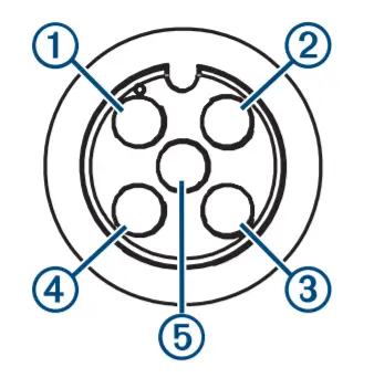
| Pin | Wire Color | Description |
| 1 | Bare | Shield |
| 2 | Red | Power, positive |
| 3 | Black | Power, negative |
| 4 | White | CAN High |
| 5 | Blue | CAN Low |
NMEA®0183 Connection Considerations
- The Chartplotter provides one Tx (transmit) port and one Rx (receive) port.
- Each port has 2 wires, labeled A and B according to the NMEA 0183 convention. The corresponding A and B wires of each internal port should be connected to the A (+) and B (-) wires of the NMEA 0183 device.
- You can connect one NMEA 0183 device to the Rx port to input data to this Chartplotter, and you can connect up to three NMEA 0183 devices in parallel to the Tx port to receive data output by this Chartplotter.
- See the NMEA 0183 device installation instructions to identify the transmit (Tx) and receive (Rx) wires.
- You must use 28 AWG, shielded, twisted-pair wiring for extended runs of wire. Solder all connections and seal them with heat-shrink tubing.
- Do not connect the NMEA 0183 data wires from this device to the power ground.
- The power cable from the Chartplotter and the NMEA 0183 devices must be connected to a common power ground.
- The internal NMEA 0183 ports and communication protocols are configured on the Chartplotter. See the NMEA 0183 section of the Chartplotter owner’s manual for more information.
- See the Chartplotter owner’s manual for a list of the approved NMEA 0183 sentences that the Chartplotter supports.
NMEA 0183 Device Connections
This diagram illustrates two-way connections for both sending and receiving data. You can also use this diagram for one-way communication. To receive information from an NMEA 0183 device, refer to items,1 2 3 4 and 5 when connecting the Garmin device. To transmit information to an NMEA 0183 device, refer to items1, 2,3 ,6, and 7when connecting the Garmin device.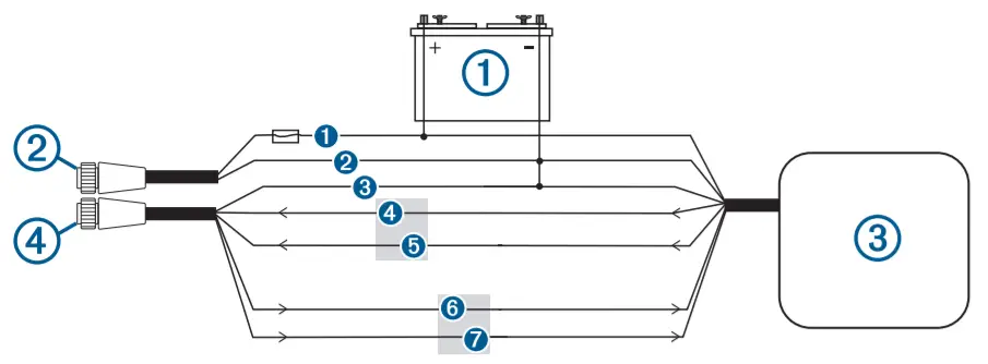
| Item | Description |
| 1 | Power source |
| 2 | Power cable |
| 3 | NMEA 0183 device |
| 4 | NMEA 0183 cable |
| Item | Garmin Wire Function | Garmin Wire Color | NMEA 0183 Device Wire Function |
| 1 | Power | Red | Power |
| 2 | Power ground | Black | Power ground |
| 3 | Data ground | Black | Data ground |
| 4 | Rx/A (In +) | White/orange | Tx/A (Out +) |
| 5 | Rx/B (In -) | White | Tx/B (Out -) |
| 6 | Tx/A (Out +) | Gray | Rx/A (In +) |
| 7 | Tx/B (Out -) | Pink | Rx/B (In -) |
If the NMEA 0183 device has only one input (receive, Rx) wire (no A, B, +, or -), you must leave the pink wire unconnected.
If the NMEA 0183 device has only one output (transmit, Tx) wire (no A, B, +, or -), you must connect the white/orange wire to the ground.
Lamp or Horn Connections
The device can be used with a lamp, a horn, or both, to sound or flash an alert when the chart plotter displays a message. This is optional, and the alarm wire is not necessary for the device to function normally. When connecting the device to a lamp or horn, observe these considerations.
- The alarm circuit switches to a low-voltage state when the alarm sounds.
- The maximum current is 100 mA, and a relay is needed to limit the current from the Chartplotter to 100 mA.
- To toggle visual and audible alerts manually, you can install single-pole, single-throw switches.
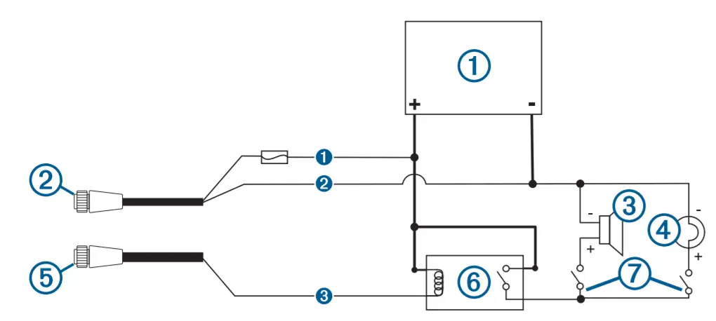
| Item | Description |
| 1 | Power source |
| 2 | Power cable |
| 3 | Horn |
| 4 | Lamp |
| 5 | NMEA 0183 cable |
| 6 | Relay (100 mA coil current) |
| 7 | Toggle switches to enable and disable lamp or horn alerts |
| Item | Wire Color | Wire Function | |
| 1 | Red | Power | |
| 2 | Black | Ground | |
| 3 | Yellow | Alarm | |
NMEA 0183 with Audio Cable Pinout
The optional NMEA 0183 with audio cable (010-12852-00) includes bare wires and an RCA connector for audio out connection to a stereo, including Fusion®stereos. This cable can be purchased from garmin.com or your local Garmin dealer.
You can connect the RCA connector to the AUX input of the stereo. Audio received from the HDMI ®input to the Chartplotter is output to the stereo.
The NMEA 0183 with audio cable provides one differential NMEA 0183 input and output port.
| Pin | Wire Function | Wire Color |
| 1 | NMEA 0183 Rx/A (In +) | White/orange |
| 2 | NMEA 0183 Rx/B (In -) | White |
| 3 | NMEA 0183 Tx/B (Out -) | Pink |
| 4 | NMEA 0183 Tx/A (Out +) | Gray |
| 5 | Ground | Black |
| 6 | Alarm | Yellow |
| 7 | Accessory on | Orange |
| 8 | Ground (shield) | Brown |
| 9 | Audio Left Channel | White |
| 10 | Audio Common | Blue/red |
| 11 | Audio Right Channel | Red |
HDMI Video Considerations
NOTICE
To prevent corrosion due to moisture, you must use Garmin GPSMAP accessory cables when connecting the Chartplotter to the video source or display. Do not connect a media player stick directly into the back of the Chartplotter. Using different cables or connecting a media player stick into the back of the chart plotter voids your warranty.
This Chartplotter allows video input from HDMI video sources, such as a Chromecast ™ device or a Blu-Ray™ player. You can view protected HDMI content (HDCP content) on the Chartplotter screen, but not on an external screen.
HDMI video is shared across the Garmin Marine Network, but it is not shared across the NMEA 2000 network. HDCP content is not shared across the Garmin Marine Network.
Through the HDMI OUT port, you can display the Chartplotter on an external screen, such as a television or monitor. You cannot view HDCP content on an external screen.
The Garmin GPSMAP HDMI accessory cable is 4.5 m (15 ft) long. If you need a longer cable, you should use an active HDMI cable only. You need an HDMI coupler to connect the two HDMI cables.
You need a Garmin GPSMAP USB OTG adapter cable to power a media player stick. The USB port can supply up to 2.5 W to power a media player stick.
You must make all cable connections in a dry environment.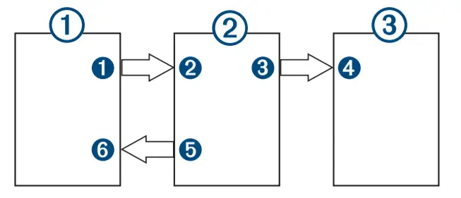
Devices
| Item | Device |
| 1 | HDMI source, such as a Chromecast device |
| 2 | GPSMAP Chartplotter |
| 3 | Monitor, such as a computer or television |
Connections
| From | To | Cable |
1HDMI source’s HDMI OUT port | 2Chartplotter’s HDMI IN port | Garmin HDMI Cable |
3Chartplotter’s HDMI OUT port | 4Monitor’s HDMI IN port | Garmin HDMI Cable |
5Chartplotter’s USB port | 6HDMI source’s USB port | GPSMAP USB OTG adapter cable to power the HDMI source, if possible (2.5 W maximum) |
Composite Video Considerations
This Chartplotter allows video input from composite video sources using the port labeled CVBS IN. When connecting composite video, you should observe these considerations.
- The CVBS IN port uses a BNC connector. You can use a BNC to RCA adapter to connect a composite-video source with RCA connectors to the CVBS IN port.
- Video is shared across the Garmin Marine Network, but it is not shared across the NMEA 2000 network.
Touchscreen Controls for a Connected Computer
NOTICE
To prevent corrosion due to moisture, you must use Garmin GPSMAP accessory cables when connecting the Chartplotter to the computer. Using different cables voids your warranty.
You can connect the Chartplotter to a computer to see the computer screen on the Chartplotter touchscreen and control the computer using the Chartplotter touchscreen. To see the computer screen, you must connect the computer to the HDMI IN port. To control the computer, you must connect the computer to the USB port.
The Garmin HDMI accessory cable (010-12390-20) is 4.5 m (15 ft) long. If you need a longer cable, you should use an active HDMI cable only. You need an HDMI coupler to connect the two HDMI cables.
The Garmin USB accessory cable (010-12390-10) is 4.5 m (15 ft) long. If you need a longer cable, you should use a USB hub or USB repeater extension cable only.
You must make all cable connections in a dry environment.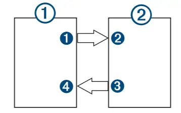
Devices
| Item | Device |
| 1 | Computer |
| 2 | GPSMAP Chartplotter |
Connections
| From | To | Cable |
1Computer’s HDMI OUT port | 2Chartplotter’s HDMI IN port | Garmin HDMI Cable |
3Chartplotter’s USB port | 4Computer’s USB port | Garmin USB Cable |
Specifications
All Models
| Specification | Measurement |
| Temperature range | From -15° to 55°C (from 5° to 131°F) |
| Material | Polycarbonate plastic and die-cast aluminum |
| Water rating | IEC 60529 IPX71 |
| Input voltage | From 10 to 32 Vdc |
| Fuse | 10 A, 125 V fast-acting |
| NMEA 2000 LEN © 9 Vdc | 2 |
| NMEA 2000 draw | 75 mA max. |
| Clearance behind flush-mounted device | 11.1 cm (43/8 in.) |
| Memory card | 2 microSD card slots in the back of the device; 32 GB max. card size |
| Wireless frequency and transmit power | 2.4 GHz @ 12.3 dBm maximum |
¹The device withstands incidental exposure to water of up to 1 m for up to 30 min.
For more information, go to www.garmin.com/waterrating.
8×10 Models
| Specification Dimensions (W x H x D) | Measurement 25.9 x 20.5 x 7.5 cm (10.25 x 8.0625 x 2.95 in.) |
| Display size (W x H) | 21.8 x 13.7 cm (8.6 x 5.4 in.) 10 in. diagonal |
| Weight | 2.4 kg (5.2 lb.) |
| Compass-safe distance | 45 cm (17.7 in.) |
| Max. power usage at 10 Vdc | 40.1 W |
| Typical current draw at 12 Vdc | 1.5 A |
| Max. current draw at 12 Vdc | 6.0 A |
8×12 Models
| Specification | Measurement |
| Dimensions (W x H x D) | 30.3 x x 21.6 x 7.5 cm (11.9 x 8.5 x 3 in.) |
| Display size (W x H) | 25.7 x 14.5 mm (10.1 x 5.7 in.) 11.6 in. diagonal |
| Weight | 2.7 kg (6.0 lb.) |
| Compass-safe distance | 35 cm (13.8 in.) |
| Max. power usage at 10 Vdc | 45 W |
| Typical current draw at 12 Vdc | 1.3 A |
| Max. current draw at 12 Vdc | 6.0 A |
8×16 Models
| Specification | Measurement |
| Dimensions (W x H x D) | 38.5 x 26.3 x 7.5 cm (15.1 x 10.3 x 3 in.) |
| Display size (W x H) | 34.5 x 19.5 cm (13.6 x 7.7 in.) 15.6 in. diagonal |
| Weight | 4.4 kg (9.6 lb.) |
| Compass-safe distance | 105 cm (41.3 in.) |
| Max. power usage at 10 Vdc | 52.1 W |
| Typical current draw at 12 Vdc | 1.3 A |
| Max. current draw at 12 Vdc | 6.0 A |
NMEA 2000 PGN Information
Transmit and Receive
| PGN V 059392 | Description ISO acknowledgment |
| 059904 | ISO request |
| 060160 | ISO transport protocol: Data transfer |
| 060416 | ISO transport protocol: Connection management |
| 060928 | ISO address claimed |
| 065240 | Commanded address |
| 126208 | Request group function |
| 126996 | Product information |
| 126998 | Configuration information |
| 127237 | Heading/track control |
| 127245 | Rudder |
| 127250 | Vessel heading |
| 127258 | Magnetic variance |
| 127488 | Engine parameters: Rapid update |
| 127489 | Engine parameters: Dynamic |
| 127493 | Transmission parameters: Dynamic |
| 127505 | Fluid level |
| 127508 | Battery status |
| 128259 | Speed: Water referenced |
| 128267 | Water depth |
| 129025 | Position: Rapid update |
| PGN 129026 | Description COG and SOG: Rapid update |
| 129029 | GNSS position data |
| 129283 | Cross track error |
| 129284 | Navigation data |
| 129539 | GNSS DOPs |
| 129540 | GNSS satellites in view |
| 130060 | Label |
| 130306 | Wind data |
| 130310 | Environmental parameters (obsolete) |
| 130311 | Environmental parameters (obsolete) |
| 130312 | Temperature (obsolete) |
Transmit
| PGN Description | |
| 126464 | Transmit and receive PGN list group function |
| 126984 | Alert Response |
| 127497 | Trip parameters: Engine |
Receive
| PGN | Description |
| 065030 | Generator average basic AC quantities (GAAC) |
| 126983 | Alert |
| 126985 | Alert text |
| 126987 | Alert threshold |
| 126988 | Alert value |
| 126992 | System time |
| 127251 | Rate of turn |
| 127257 | Attitude |
| 127498 | Engine parameters: Static |
| 127503 | AC input status (obsolete) |
| 127504 | AC output status (obsolete) |
| 127506 | DC detailed status |
| 127507 | Charger status |
| 127509 | Inverter status |
| 128000 | Nautical leeway angle |
| 128275 | Distance log |
| 129038 | AIS class A position report |
| 129039 | AIS class B position report |
| 129040 | AIS class B extended position report |
| 129044 | Datum |
| 129285 | Navigation: Route, waypoint information |
| 129794 | AIS class A static and voyage related data |
| 129798 | AIS SAR aircraft position report |
| 129799 | Radiofrequency/mode/power |
| 129802 | AIS safety-related broadcast message |
| 129808 | DSC call Information |
| 129809 | AIS class B “CS” static data report, part A |
| 129810 | AIS class B “CS” static data report, part B |
| 130313 | Humidity |
| 130314 | Actual pressure |
| 130316 | Temperature: Extended range |
| 130576 | Trim tab status |
| 130577 | Direction data |
NMEA 0183 Information
Transmit
| Sentence | Description |
| GPAPB | APB: Heading or track controller (autopilot) sentence “B” |
| GPBOD | BOD: Bearing (origin to destination) |
| GPBWC | BWC: Bearing and distance to waypoint |
| GPGGA | GGA: Global positioning system fix data |
| GPGLL | GLL: Geographic position (latitude and longitude) |
| GPGSA | GSA: GNSS DOP and active satellites |
| GPGSV | GSV: GNSS satellites in view |
| GPRMB | RMB: Recommended minimum navigation information |
| GPRMC | RMC: Recommended minimum specific GNSS data |
| GPRTE | RTE: Routes |
| GPVTG | VTG: Course over ground and ground speed |
| GPWPL | WPL: Waypoint location |
| GPXTE | XTE: Cross-track error |
| PGRME | E: Estimated error |
| PGRMM | M: Map datum |
| PGRMZ | Z: Altitude |
| SDDBT | DBT: Depth below transducer |
| SDDPT | DPT: Depth |
| SDMTW | MTW: Water temperature |
| SDVHW | VHW: Water speed and heading |
Receive
| Sentence | Description |
| DPT | Depth |
| DBT | Depth below transducer |
| MTW | Water temperature |
| VHW | Water speed and heading |
| WPL | Waypoint location |
| DSC | Digital selective calling information |
| DSE | Expanded digital selective calling |
| HDG | Heading, deviation, and variation |
| HDM | Heading, magnetic |
| MWD | Wind direction and speed |
| MDA | Meteorological composite |
| MWV | Wind speed and angle |
| VDM | AIS VHF data-link message |
You can purchase complete information about National Marine Electronics Association (NMEA) format and sentences from www.nmea.org.
J1939 Information
The Chartplotter can receive J1939 sentences. The Chartplotter cannot transmit over the J1939 network.
| Description | PGN | SPN |
| Engine percent load at the current speed | 61443 | 92 |
| Engine speed | 61444 | 190 |
| Engine manifold exhaust gas temperature – right manifold | 65031 | 2433 |
| Engine manifold exhaust gas temperature – left manifold | 65031 | 2434 |
| Engine auxiliary coolant | 65172 | |
| Active diagnostic trouble codes | 65226 | |
| Vehicle distance | 65248 | |
| Water in fuel indicator | 65279 | |
| Engine wait to start lamp | 65252 | 1081 |
| Engine over-speed test | 65252 | 2812 |
| Engine air shutoff command status | 65252 | 2813 |
| Engine alarm output command status | 65252 | 2814 |
| Description | PGN | SPN |
| Engine total hours of operation | 65253 | 247 |
| Navigation-based vehicle speed | 65256 | 517 |
| Engine fuel temperature 1 | 65262 | 174 |
| Engine oil temperature 1 | 65262 | 175 |
| Engine fuel delivery pressure | 65263 | 94 |
| Engine oil pressure | 65263 | 100 |
| Engine coolant pressure | 65263 | 109 |
| Engine coolant temperature | 65263 | 110 |
| Engine coolant level | 65263 | 111 |
| Engine fuel rate | 65266 | 183 |
| Engine average fuel economy | 65266 | 185 |
| Engine intake manifold #1 pressure | 65270 | 102 |
| Battery potential/power input 1 | 65271 | 168 |
| Transmission oil temperature | 65272 | 177 |
| Transmission oil pressure | 65272 | 127 |
| Fuel level | 65276 | 96 |
| Engine oil filter differential pressure | 65276 | 969 |
© 2019 Garmin Ltd. or its subsidiaries Garmin®, the Garmin logo, and GPSMAP®are trademarks of Garmin Ltd. or its subsidiaries, registered in the SA and other countries. These trademarks may not be used without the express permission of Garmin.HDMI® is a registered trademark of HDMI Licensing, LLC. The microSD ®logo is a trademark of SD-3C, LLC. NMEA®, NMEA 2000®, and the NMEA 2000 logo are registered trademarks of the National Marine Electronics Association.
© 2019 Garmin Ltd. or its subsidiaries
support.garmin.com
![]() GUID-871DF8A0-D7F0-41CD-BC39-FB7822E19BFB v2
GUID-871DF8A0-D7F0-41CD-BC39-FB7822E19BFB v2
October 2020


