![]() OEM-1 REV.10-23-02
OEM-1 REV.10-23-02
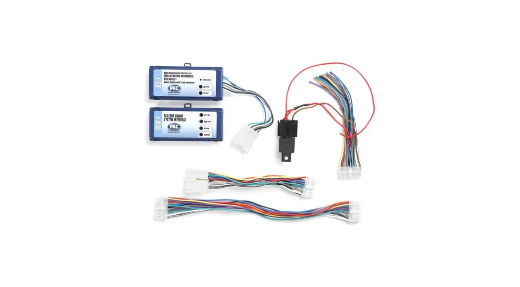
Cables for replacing Factory head unit.
Instruction Manual
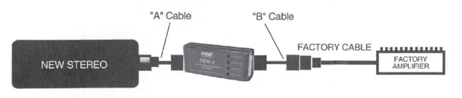
Installation instructions for cables on Jist “A”
The “A” cable, is used when replacing a factory radio. (the appropriate cable from list “8” is also required). One end of cable plugs into or connects to your new aftermarket head unit and the other end plugs into the 18 pin connector of the OEM-1_ When using the complete OEM-1 system the radio will be current protected by the vehicle fuse. The installer must decide to transfer any other fuses or noise filters from the harness provided with the head unit. Use the wire I terminal identification chart below to locate the correct power wires. The low level inputs are for radios up to 25watts x 4.
While every effort has been made to insure this cable was made to connect properly to your aftermarket head unit, changes in models and configurations do occur. To prevent potential damage consult your stereo’s owners manual and check wire function (as shown below) with that of the head unit you have. Move any wires that are not in the correct pin location for you head unit.
Installation instructions for cables on list “B”
The “B” cable, is used when replacing a factory radio. (the appropriate cable from list “A” is also required). One end of this cable plugs into the vehicle dash harness that was removed from the factory radio. (the AMP-U NV harness must be spliced into the vehicle harness, use the 16 pin chart below for wire identification) The other end plugs into the 16 pin connector of the OEM-1.
WIRE AND TERMINAL /DENT/FICA TION
Output of the OEM-1, 16 pin connector (cable “B” or AMP-RCA). Looking into connector I wire side of cable.
| WIRE COLOR | CIRCUIT | CIRCUIT | WIRE COLOR | ||
| ORANGE | ILLUMINATION | 8 | 16 | IGNITION SWITCH 12V | RED |
| BLUE/WHITE | AMP TRIGGER | 7 | 15 | BATTERY | YELLOW |
| BLACK | GROUND | 6 | 14 | POWER ANTENNA | BLUE |
| PURPLE/ BLK | RIGHT REAR(-) | 5 | 13 | RIGHT REAR (+) | PURPLE |
| GREEN/ BLACK | LEFT REAR(-) | 4 | 12 | LEFT REAR(+) | GREEN |
| N/C | 3 | 11 | N/C | ||
| GRAY/BLACK | RIGHT FRONT(-) | 2 | 10 | RIGHT FRONT(+) | GRAY |
| WHITE/ BLACK | LEFT FRONT (-) | 1 | 9 | LEFT FRONT (+) | WHITE |
Input of the OEM-1 , 18 pin connector (cable “A” or “C”). Looking into connector I wire side of cable.
| WIRE COLOR | CIRCUIT | CIRCUIT | WIRE COLOR | ||
| WHITE/ BLK | LEFT FRONT (-) | 9 | 18 | LEFT FRONT LOW LEVEL + | WHITE/ RED |
| GRAY/BLK | RIGHT FRONT(-) | 8 | 17 | LEFT FRONT HIGH LEVEL + | WHITE |
| GREEN/BLK | LEFT REAR(-) | 7 | 16 | RIGHT FRONT LOW LEVEL(+) | GRAY/RED |
| PURPLE/ BLK | RIGHT REAR(-) | 6 | 15 | RIGHT FRONT HIGH LEVEL(+) | GRAY |
| BLACK | GROUND | 5 | 14 | LEFT REAR LOW LEVEL(+) | GREEN/RED |
| BLUE | POWER ANTENNA | 4 | 13 | LEFT REAR HIGH LEVEL + | GREEN |
| ORANGE | ILLUMINATION/ DIMMER | 3 | 12 | RIGHT REAR LOW LEVEL(+) | PURPLE/ RED |
| BLUE/WHITE | AMP TRIGGER | 2 | 11 | RIGHT REAR HIGH LEVEL (+ ) | PURPLE |
| RED | IGNITION/ SWITCHED | 1 | 10 | BATTERY | YELLOW |
Cables for adding or replacing factory amplifier.
Installation instructions for cables on list “C”
The “C” cable, is used when replacing or adding aftermarket amplifiers to a factory amplified system. (the cable model# AMP-RCA is also required) This cable plugs in between the factory rad io and the dash harness that was removed from the factory radio. The 18 pin connector then plugs into the OEM-1. The factory system remains unchanged using this cable. The ADD-UNV cable is used for universal connection to the vehicle harness for vehicles not listed. (splicing required) Audio should be at a low level when using this cable.
Use the AMP-RCA cable connected to the 16 pin connector of the OEM-1 to connect your aftermarket amplifier. The AMP-RCA provides 2 pair of female RCA jacks and a remote turn on lead.
Installation instructions for the AMP-RCA cable
This cable is used when replacing or adding aftermarket amplifiers to a factory amplified system. (the appropriate cable from list “C” is also required) The AMP-RCA cable connects to the 16 pin connector of the OEM-1 and provides 2 pair of female RCA jacks and a remote turn on lead for connection to your aftermarket amplifier. 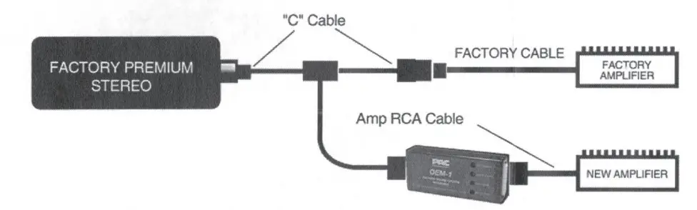
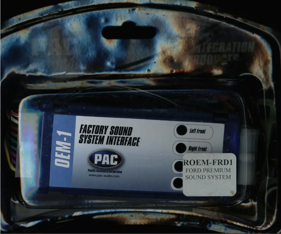
ROEM-FRD1
Premium Sound System Interface
This interface will allow the replacement of a stereo in the following Ford vehicles with a Mach or JBL premium sound system. The interface is transformer isolated, maintains phase and is linear from 20 to 20,000 HZ. This 4 channel interface will allow the new stereo’s output to be adjusted to the input requirements of the existing factory installed ampliflier, providing 2:1 gain and infinite attenuation.
The output connector plugs directly into the factory harness. The color coded input wires are connected to the new stereo’s output harness.
For use with:
94-99 Mustang Mach System
89-95 Ford JBL System
Since 1976, when the 8-track player was the iPod of the day, PAC has been manufacturing high quality and rock solid mobile electronics interfaces that satisfy even the most demanding customer. Our patented and award-winning products deliver the performance and functionality you want and deserve.
No matter what the challenge, our deep engineering and manufacturing knowledge and experience produce solutions you can count on!
Compatibility:
This product may have specific compatibility requirements to operate correctly in your automobile. Please consult a sales associate or visit www.pac-audio.com to learn whether or not your specific car and/or radio are compatible.
Due to continuous product improvement, Pacific Ac:cessory Corporation reserves the right to make changes to product or specifications described herein with out notice.![]() Please Recycle
Please Recycle
P-PACK2C
Pacific Accessory Corporation
Santa Ana, California 92705
[email protected]
www.paceaudio.com 866-931-8021
© 2009 Pacific Accessory Corporation
Designed and Engineered in the USA,
Manufactured in China
Sales 800-477-2267
www.Pac-audio.com
2500 E. Francis St. Ontario, CA 91761
Tech support 866-931-8021
[email protected]