
![]() 4056946 Solar Heating Pump
4056946 Solar Heating Pump
Instruction Manual
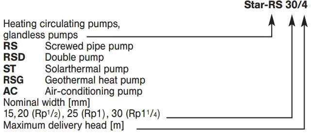
Wilo-Star RS, RSD, ST, RSG, AC
4056946 Solar Heating Pump
 |  |
 |  |
General Information
These Operating Instructions explain the functions and operation of the pump when installed and ready for use. The figures referred to in the text can be found on the fold-out page at the front.
Use as prescribed
The circulating pump (hereafter referred to simply as a pump or general unit) is used to pump liquids in pipe systems.![]() The pump must not be used for handling drinking water or food-related liquids.
The pump must not be used for handling drinking water or food-related liquids.
Its main fields of application are:
- Hot-water heating, various systems,
- Industrial, closed circulating systems.
Specific details:
- Type ST: for thermal solar systems
- Type RSG: for geothermal systems
- Type AC: for air-conditioning units and cold-water distribution.
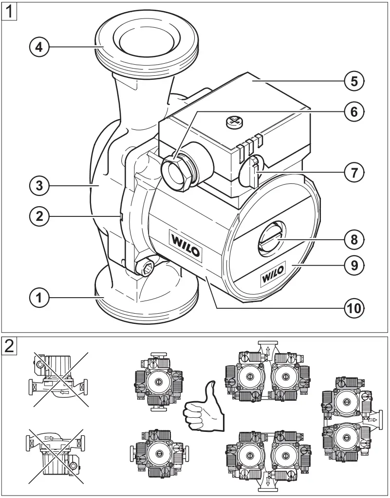
Terms (Fig. 1)
- Suction joint
- Condensate outlet
- Pump housing
- Pressure joint
- Terminal box
- Cable entry
- Speed switch
- Ventilation
- Rating plate
- Motor housing
Rating plate
Connection and electrical data
| Voltage: | 1~230V ±10% | Speed setting: | 3 stages * |
| Mains frequency: | 50Hz | Fitting length: | 130/180 mm |
| Power consumption Pmax: | Rating plate | Perm. operating pressure, max.: | 10 bar |
| Motor speed, max.: | Rating plate | Perm. medium temperatures min./max.: | -10/+110 °C |
| Protection category IP: | Rating plate | Perm. ambient temperatures max.: | +40 °C |
| Min. inlet pressure** | at the suction side at |
| + 50 °C: | 0.05 bar |
| + 95 °C: | 0.3 bar |
| + 110 °C: | 1.0 bar |
* For double pumps the additional switchgear S2R 3D is required for time-controlled main/reserve or additional/peak-load operation.
** The values are valid up to 300 m above sea level. For higher elevations add: 0.01 bar/100 m.
The minimum inlet pressure must be maintained in order to avoid cavitation noise!
Permissible fluids:
- Heating water acc. to VDI 2035
- Water and water/glycol mixtures in a ratio up to 1:1. Glycol mixtures require a reassessment of pump hydraulic data in line with the increased viscosity and depending on mixing ratios. Only approved makes of additives with corrosion inhibitors must be used in strict compliance with manufacturers’ instructions.
- For use of other kinds of fluids consult WILO first.
Safety
These instructions contain basic references which must be strictly adhered to. It is therefore imperative for the installer and operator to carefully read these instructions prior to installation and commissioning.
Please observe, not only the safety directions under the main heading „safety rules“, but also those added and specially marked under the ensuing headers.
Safety marks contained in these instructions
Safety rules contained herein which, if not complied with, may be dangerous to persons are especially highlighted by the following danger symbols:![]() Danger from electrical causes:
Danger from electrical causes:![]() Safety references which, if not complied with, may cause damage to the pump/installation or impair its functions are highlighted by the word:
Safety references which, if not complied with, may cause damage to the pump/installation or impair its functions are highlighted by the word:
ATTENTION
Staff training
The personnel installing the pump/unit must have the appropriate qualifications for this work.
Dangers from non-observance of safety rules
Non-observance of safety references may cause personal injury or damage to the pump or installation. Failure to comply with the safety references could invalidate the warranty and/or damage claims.
In particular, non-compliance may, for example, cause the following dangerous situations:
- Failure of the important pump or unit functions,
- Causing personal injury due to electrical or mechanical causes.
Safety rules for the operator
Local regulations for the prevention of accidents must be observed.
Dangers caused by electrical energy must be excluded. Local or general regulations [e.g. IEC, VDE, etc.] and directives from local energy supply companies are to be followed.
Safety rules for inspection and installation work
The operator must ensure that all inspection and installation work is carried out by authorized and qualified specialists who have carefully studied these instructions.
Work on the pump/unit must be carried out only with the machine switched off and at a complete standstill.
Unauthorized modification and manufacture of spare parts
Alterations to the pump or installation may only be carried out with the manufacturer’s agreement. The use of original spare parts and accessories authorized by the manufacturer will ensure safety. The use of any other parts may invalidate claims invoking the liability of the manufacturer for any consequences.
Unauthorized operating methods
The operating safety of the pump or installation supplied can only be guaranteed if it is used in accordance with paragraph 1 of the operating instructions. Under no circumstances should the limit values given in the datasheet be exceeded.
Transport/Interim storage
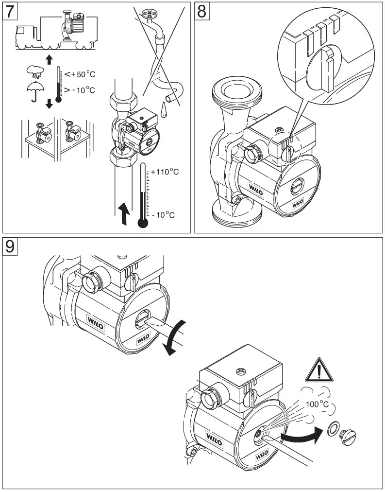
ATTENTION!
The pump contains electronic components and must be protected against moisture from outside and mechanical damage (shock/impact) (Fig. 7). It must not be exposed to temperatures outside the range of -10 °C to +50 °C. (Fig. 7).
Description of pump/accessories
Products delivered
- Complete pump
- 2 flat gaskets,
- Installation and operating instructions
Pump description
In the wet-running pump, all rotating parts are surrounded by the flow medium, including the motor rotor.
A shaft seal, which would be subject to wear and tear, is not required. The pumping medium lubricates the friction bearing and cools both the bearing and rotor.
No motor overload protection is required.
Even the maximum overload current cannot damage the motor. The motor operates non-overloading.
Speed setting (Fig. 8)
The speed of the pump can be adjusted with a 3-position rotary button. In position 3 the speed is approx. 40…50 % of the maximum speed with the power consumption being reduced to 50 %.
Particular features of the pumps Double pumps contain two identically constructed pump heads in a common pump housing with an integrated change-over flap. Each pump can run in a single mode, and both pumps can also run simultaneously in parallel mode. The operating modes are main/reserve operation or incremental/peak-load operation. The pump heads can be selected in different capacities. Double pumps are suitable for adapting a pipe system to suit individual load characteristics. The S2R 3D control unit must be connected to control the different operating modes.
The ST… and RSG… pumps are pumps with special hydraulics for use in solar thermal systems (Type ST…) or geothermal systems (Type RSG…).
The AC 20/…-I(O) pump is an air conditioning pump with a plastic (composite) pump housing for use in air-conditioning units and cold-water distribution.
In the AC ../..-I:
(I = inline) pump the pump housing is designed „inline“-, i. e. suction and pressure connections are in line.
The AC ../..-O:
(O = offline) the pump is equipped with axial suction and radial discharge connection.
Accessories
Accessories must be ordered separately.
- Inserts for the pipe connection of the screwed-pipe pump.
- S2R 3D switchgear for the double pump.
- Thermal insulating units for later insulation of the ST/RSG 25 pump.
Assembly/Installation
Installation
ATTENTION
Installation and service by qualified personnel only!
- Assembly should only take place once all welding and soldering work and the rinsing of the pipe network have been completed. Dirt can have an adverse effect on the functioning of the pump.
- The pump must be installed in an easily accessible position to facilitate inspection or replacement.
- It is recommended that shut-off devices be fitted before and after the pump. This will save having to drain and refill the system if the pump needs replacing. The fittings are to be installed so that any water that escapes cannot drip onto the pump motor or terminal box.
- When installed into the flow pipe of an open-vented system, the open safety vent must be connected to the system on the inlet side of the pump.
- The pump is to be mounted with the shaft in the horizontal plane in such a way that it is not stressed by the pipework. (Installation positions in Fig. 2).
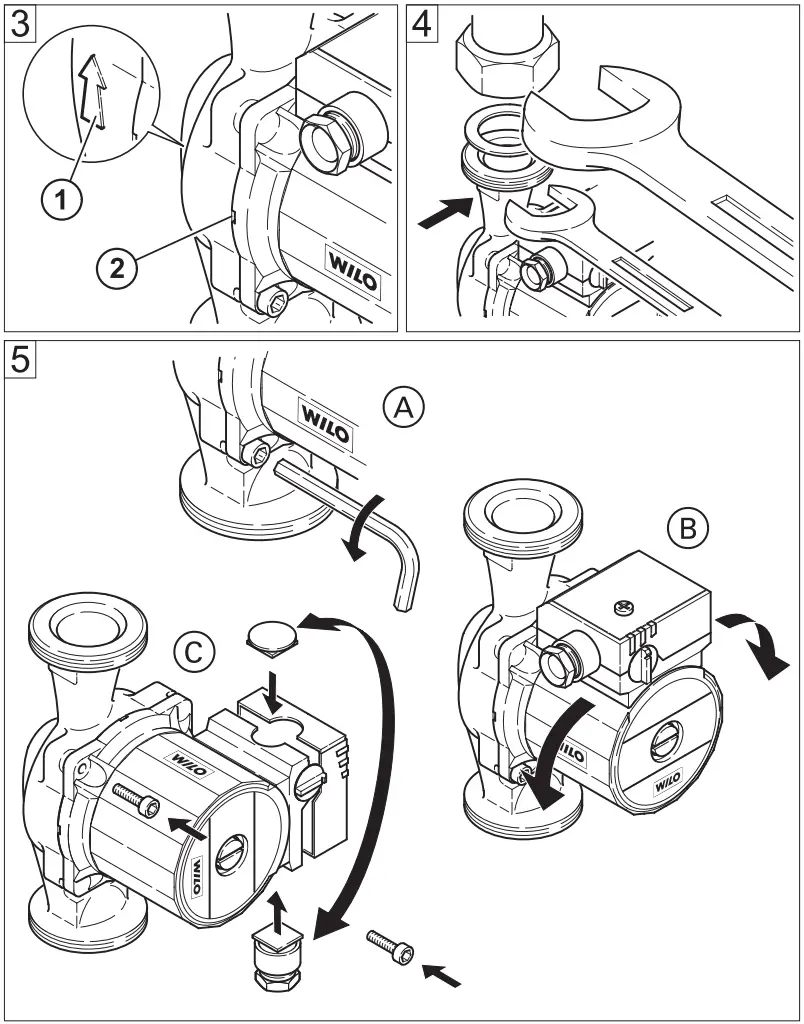
- An arrow on the pump casing indicates the direction of flow (Fig. 3, pos.1).
- Secure the pump against twisting by using a spanner (Fig. 4).
- In order to attain the correct terminal box position the motor housing can be turned once the motor fastening screws have been loosened (Fig. 5).
ATTENTION: Do not damage the flat gasket. If necessary use a new gasket: Ø 86 x Ø 76 x 2.0 mm EP.
ATTENTION: For units that are to be insulated, only the pump housing may be insulated. The motor and condensate openings must remain free (Fig. 3, pos. 2).
Electrical connection![]() Electrical connection must be carried out by a qualified and licensed electrician in strict conformity to ruling national conditions and local regulations (e.g. VDE regulations in Germany).
Electrical connection must be carried out by a qualified and licensed electrician in strict conformity to ruling national conditions and local regulations (e.g. VDE regulations in Germany).
- According to Part 1 of the VDE 0730, the pump must be connected to the electrical supply by a solid wire equipped with a plug connection or an all-pole switch. The width of the contact gap must be at least 3 mm.
- To guarantee protection against dripping water and the strain relief of the PG screwed joint, a connecting cable of suitable external diameter is to be used (e.g. H 05 VV-F 3 G 1.5).
- When using the pump in units where the water temperature exceeds 90 °C, a connecting cable with corresponding heat resistance must be used.
- The supply cable must be laid in such a way that it never touches the pipework and/or the pump and motor casing.
- Check that the mains current and voltage comply with the data on the rating plate.
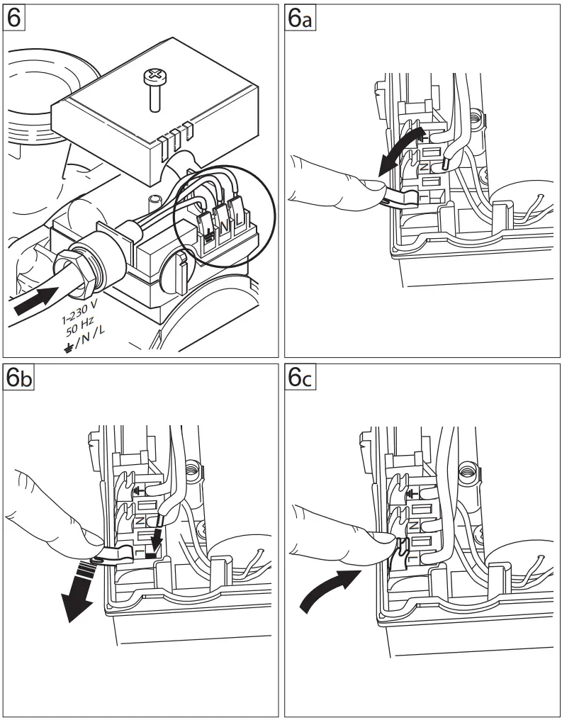
- Make a mains connection as shown in Fig. 6.
- The connecting cable can be fed through the PG screwed joint either to the left or right. If necessary, the blind plug and PG screwed joint are to be exchanged. If the terminal box is positioned on the side, always insert the PG screwed joint from below (Fig. 5)
![]() Caution risk of short-circuit!
Caution risk of short-circuit!
After electrical connections the terminal box cover must be closed properly, to protect against moisture.
- The pump/installation must be earthed in compliance with regulations.
- When connecting automatic switchgear (for double pumps), follow the appropriate Installation and Operating Instructions.
Operation
System filling and venting
The pump may need venting e.g. if the heating and pump are working but the heating element remains cold. If there is air in the pump chamber, the pump will not pump water.
Carefully fill the unit with water.
Solar thermal systems must be filled with ready-for-use mixtures. The pump must not be used to mix the medium in the system.
The pump is normally vented automatically after a short operational period. Short-term dry running will not damage the pump. If it becomes necessary to vent the pump, please observe the following procedure:
- Switch off the pump,
![]() Risk of burning if the pump is touched!
Risk of burning if the pump is touched!
Depending on the operating condition of the pump and/or installation (fluid temperature) the pump/motor can become very hot.
- Close the valve on the discharge side.
![]() Risk of scalding!
Risk of scalding!
Depending on the fluid temperature and the system pressure, if the vent screw is completely loosened hot liquid or vapor can escape or even shoot out at high pressure.
- Carefully loosen and fully remove the vent plug with a suitable screwdriver (Fig. 9).
- Carefully push the pump shaft back several times with a screwdriver.
- Protect all electrical parts from leaking water.
- Switch-on pump.
ATTENTION
It is possible that the pump blocks with the vent plug open, depending on the system pressure.
- After 15…30 s tighten the vent plug.
- Re-open isolating valve,
Speed setting
If the rooms cannot be sufficiently heated, the speed of the pump may be too low. In this case, you will need to switch to a higher speed.
If, on the other hand, the pump is set at too high a speed, flow noise may occur in the lines and in particular at throttled thermostatic valves. This can be rectified by switching to a lower speed.
The speed is changed by means of a rotary button at the terminal box. 3 represents the lowest and 1 the highest speed.
Maintenance
![]() Prior to maintenance or repair work switch off the pump and secure it against unauthorized switching.
Prior to maintenance or repair work switch off the pump and secure it against unauthorized switching.
Problems, Causes, and Remedies
The motor is switched on but fails to run:
- Check electrical fuses,
- Check the voltage of the pump (observe rating plate data),
- Check capacitor size (observe rating plate data!).
- The motor is blocked, e.g. by deposits from the heating water.
- Remedies: Fully remove the vent plug, check and if necessary rectify the free running of the pump rotor by turning the slotted end of the shaft with a screwdriver (Fig. 9).
 At high water temperatures and system pressure close isolating valves before and after the pump. First, allow the pump to cool down
Noisy pump operation
- Cavitation due to insufficient inlet pressure.
- Remedies: increase system pressure within the permissible range.
- Check the speed setting, if necessary switch to a lower speed.
If the fault cannot be rectified, contact your nearest WILO Customer Service.
Spare parts
All rating plate data must be stated when ordering spare parts.
Subject to technical alterations!
EC – Declaration of conformity
Herewith, we declare that this product:
- Star RS
- Star RSD
- Star RSG
- Star ST
- Star AC
in its delivered state complies with the following relevant provisions:
Electromagnetic compatibility – directive: 2004/108/EG
Low voltage directive: 2006/95/EG
and with the relevant national legislation.
Applied harmonized standards, in particular:
- EN 1050
- EN 61000-6-1
- EN 61000-6-2
- EN 61000-6-3
- EN 61000-6-4
- EN 61335-2-51
If the above-mentioned series are technically modified without our approval, this declaration shall no longer be applicable.
Dortmund, 07.11.2008
![]()
WILO SE
Nortkirchenstraße 100
44263 Dortmund
Germany
Wilo – International (Subsidiaries)
| Argentina WILO SALMSON Argentina S.A. C1270ABE Ciudad Autónoma de Buenos AirT +54 11 43015955 [email protected] Austria WILO Pumpen Österreich GmbH 1230 Wien T +43 507 507-0 [email protected] Azerbaijan WILO Caspian LLC 1065 Baku T +994 12 5962372 [email protected] Belarus WILO Bel OOO 220035 Minsk T +375 17 2503393 [email protected] Belgium WILO SA/NV 1083 Ganshoren T +32 2 4823333 [email protected] Bulgaria WILO Bulgaria Ltd. 1125 Sofia T +359 2 9701970 [email protected] Canada WILO Canada Inc. Calgary, Alberta T2A 5L4 T +1 403 2769456 [email protected] China WILO China Ltd. 101300 Beijing T +86 10 80493900 [email protected] Croatia WILO Hrvatska d.o.o. 10090 Zagreb T +38 51 3430914 [email protected] | Czech Republic WILO Praha s.r.o. 25101 Cestlice T +420 234 098711 [email protected] Denmark WILO Danmark A/S 2690 Karlslunde T +45 70 253312 [email protected] Estonia WILO Eesti OÜ 12618 Tallinn T +372 6509780 [email protected] Finland WILO Finland OY 02330 Espoo T +358 207401540 [email protected] France WILO S.A.S. 78390 Bois d’Arcy T +33 1 30050930 [email protected] Great Britain WILO (U.K.) Ltd. DE14 2WJ BurtonUpon-Trent T+44 1283 523000 [email protected] Greece WILO Hellas AG 14569 Anixi (Attika) T +302 10 6248300 [email protected] Hungary WILO Magyarország Kft 2045 Törökbálint (Budapest) T +36 23 889500 [email protected] Ireland WILO Engineering Ltd. Limerick T +353 61 227566 [email protected] | Italy WILO Italia s.r.l. 20068 Peschiera Borromeo (Milano) T +39 25538351 [email protected] Kazakhstan WILO Central Asia 050002 Almaty T +7 727 2785961 [email protected] Korea WILO Pumps Ltd. 621-807 Gimhae Gyeongnam T +82 55 3405800 [email protected] Latvia WILO Baltic SIA 1019 Riga T +371 67 145229 [email protected] Lebanon WILO SALMSON Lebanon 12022030 El Metn T +961 4 722280 [email protected] Lithuania WILO Lietuva UAB 03202 Vilnius T +370 5 2136495 [email protected] The Netherlands WILO Nederland b.v. 1551 NA Westzaan T +31 88 9456 000 [email protected] Norway WILO Norge AS 0975 Oslo T +47 22 804570 [email protected] Poland WILO Polska Sp. z.o.o. 05-090 Raszyn T +48 22 7026161 [email protected] | Portugal Bombas Wilo-Salmson Portugal Lda. 4050-040 Porto T +351 22 2080350 [email protected] Romania WILO Romania s.r.l. 077040 Com. Chiajna Jud. IlfovT +40 21 3170164 [email protected] Russia WILO Rus ooo 123592 Moscow T +7 495 7810690 [email protected] Saudi Arabia WILO ME – Riyadh Riyadh 11465 T +966 1 4624430 [email protected] Serbia and Montenegro WILO Beograd d.o.o. 11000 Beograd T +381 11 2851278 [email protected] Slovakia WILO Slovakia s.r.o. 82008 Bratislava 28 T +421 2 45520122 [email protected] Slovenia WILO Adriatic d.o.o. 1000 Ljubljana T +386 1 5838130 [email protected] South Africa Salmson South Africa 1610 Edenvale T +27 11 6082780 [email protected] Spain WILO Ibérica S.A. 28806 Alcalá de Henares (Madrid) T +34 91 8797100 [email protected] | Sweden WILO Sverige AB 35246 Växjö T +46 470 727600 [email protected] Switzerland EMB Pumpen AG 4310 Rheinfelden T +41 61 83680-20 [email protected] Taiwan WILO-EMU Taiwan Co. Ltd. 110 Taipeh T +886 227 391655 nelson.wu@wiloemutaiwan. com.tw Turkey WILO Pompa Sistemleri San. ve Tic. A.S¸. 34530 Istanbul T +90 216 6610211 [email protected] Ukraina WILO Ukraina t.o.w. 01033 Kiew T +38 044 2011870 [email protected] Vietnam Pompes Salmson Vietnam Ho Chi Minh-Ville Vietnam T +84 8 8109975 [email protected] United Arab Emirates WILO ME – Dubai Dubai T +971 4 3453633 [email protected] USA WILO-EMU USA LLC Thomasville, Georgia 31792 T +1 229 5840097 [email protected] USA WILO USA LLC Melrose Park, Illinois 60160 T +1 708 3389456 [email protected] |
Wilo – International (Representation offices)
| Algeria Bad Ezzouar, Dar El Beida T +213 21 247979 Armenia 375001 Yerevan T +374 10 544336 Bosnia and Herzegovina 71000 Sarajevo T +387 33 714510 | Georgia 0179 Tbilisi T +995 32 306375 Macedonia 1000 Skopje T +389 2 3122058 Mexico 07300 Mexico T +52 55 55863209 | Moldova 2012 Chisinau T +373 2 223501 Rep. Mongolia Ulaanbaatar T +976 11 314843 Tajikistan 734025 Dushanbe T +992 37 2232908 | Turkmenistan 744000 Ashgabad T +993 12 345838 Uzbekistan 100015 Tashkent T +998 71 1206774 January 2009 |
![]() WILO SE
WILO SE
Nortkirchenstraße 100
44263 Dortmund Germany
T +49 231 4102-0
F +49 231 4102-7363
[email protected]
www.wilo.com


