![]() TOP-Z 57 Hot Water Circulation Pump
TOP-Z 57 Hot Water Circulation Pump
Instruction Manual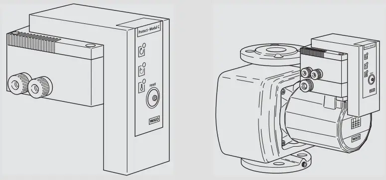 Wilo-Stratos ECO
 |  |
 |  |
 |  |
 |  |
 |  |
General
About this document
These installation and operating instructions are an integral part of the product. They must be kept readily available at the place where the product is installed. Strict adherence to these instructions is a precondition for the proper use and correct operation of the product. This installation and operating instructions conform to the relevant version of the product and the underlying safety standards valid at the time of going to press.
Safety
These instructions contain important information which must be followed when installing and operating the pump. It is therefore imperative that they be read by both the installer and the operator before the pump is installed or operated. Both the general safety instructions in this section and the more specific safety points in the following sections should be observed.
Instruction symbols used in this operating manual
Symbols:![]() General danger symbol
General danger symbol![]() Hazards from electrical causes
Hazards from electrical causes![]() NOTE: …
NOTE: …
Signal words:
DANGER!
Imminently hazardous situation. Will result in death or serious injury if not avoided.
WARNING!
Risk of (serious) injury. ‘Warning’ implies that failure to comply with the safety instructions is likely to result in (severe) personal injury.
CAUTION!
Risk of damage to the pump/installation. ‘Caution’ alerts to the user to potential product damage due to non-compliance with the safety instructions
NOTE:
Useful information on the handling of the product. It alerts the user to potential difficulties.
Personnel qualification
The personnel installing the pump must have the appropriate qualification for this work.
Risks incurred by failure to comply with the safety instructions
Failure to comply with the safety precautions could result in personal injury or damage to the pump or installation. Failure to comply with the safety precautions could also invalidate any claim for damages.
In particular, failure to comply with these safety instructions could give rise, for example, to the following risks:
- Failure of important pump or system functions,
- Personal injury due to electrical and mechanical causes.
Safety instructions for the operator
The relevant accident precaution regulations must be observed. Potential dangers caused by electrical energy must be excluded. Local or general regulations [e.g. IEC, BSI, UL, etc.] and directives from local energy supply companies are to be followed.
Safety instructions for inspection and assembly
The operator must ensure that all inspection and assembly work is carried out by authorized and qualified specialists who have carefully studied these instructions. Work on a pump or installation should only be carried out once the latter has been brought to a standstill.
Unauthorized modification and manufacture of spare parts
Changes to the pump/machinery may only be made in agreement with the manufacturer. The use of original spare parts and accessories authorized by the manufacturer will ensure safety. The use of any other parts may invalidate claims invoking the liability of the manufacturer for any consequences.
Improper use
The operating safety of the pump or installation can only be guaranteed if it is used in accordance with paragraph 4 of the operating instructions. All values must neither exceed nor fall below the limit values given in the catalog or data sheet.
Transport and interim storage
Inspect the pump/system for transport damage immediately upon arrival. Any transport damage found must be reported to the carrier within the prescribed periods.![]() CAUTION! Risk of damage to the pump! Risk of damage due to improper handling during transport or storage.
CAUTION! Risk of damage to the pump! Risk of damage due to improper handling during transport or storage.
- The pump is to be protected against moisture and mechanical damage due to impact/shock.
- The pumps must not be exposed to temperatures outside the range -10°C to +50°C.
Applications
Stratos ECO:![]() WARNING! Health hazard! The pump must not be used for pumping liquids in the fields of service/drinking water and food-related liquids.
WARNING! Health hazard! The pump must not be used for pumping liquids in the fields of service/drinking water and food-related liquids.
Series Wilo-Stratos ECO circulating pumps are intended for use in conjunction with hot water heating or similar water circulating systems of variable volume characteristics. The pump-integrated electronic differential pressure control provides infinitely-variable speed control to match pump capacity to actual load demand.
Stratos ECO-Z:
Series Wilo-Stratos ECO-Z circulating pumps are also suitable of handling liquids in the fields of service/drinking water and food-related liquids.
Product data
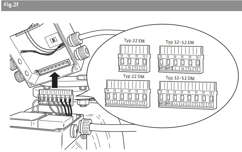
Type Key
| Example: Wilo-Protect-Modul C Type 22 EM | |
| Protect-Modu | Series designation |
| C | Comfort |
| Type 22 | Type designation: 22 or 32-52 |
| EM | For mains connection: EM = 1~230 V, 50 Hz (single-phase motor) DM = 3~400 V, 50 Hz (three-phase current motor) |
Technical data
| Technical data | |
| Connection current Type 22 EM Type 32-52 EM Type 22 DM Type 32-52 DM | 1~230 V, ±10 %, 50 Hz 1~230 V, ±10 %, 50 Hz 3~400 V, ±10 %, 50 Hz 3~400 V, ±10 %, 50 Hz |
| Frequency | 50 Hz |
| Terminal cross-section, all terminals | max. 2.5 mm 2 |
| Temperature range of flow medium | -20 °C to +110 °C |
| Max. ambient temperature | +40 °C |
| Pump protection class | IP 44 |
| Cable connections | 4xPG9 |
| Electromagnetic compatibility: Emitted interference Immunity to interference | EN 61000-6-3 EN 61000-6-2 |
Water temperature rangemax. 110 °C at ambient temperature max. 25 °C max. 95 °C at ambient temperature max. 40 °C
Suitable fluids:
- Heating water acc. to VDI 2035,
- water and water/glycol mixtures up to a 1:1 ratio. The use of glycol mixtures requires a reassessment of the pump hydraulic data in line with the increased viscosity at the various mixing ratios. Only approved makes of additives with corrosion inhibitors must be used in strict compliance with manufacturers’ instructions.
- For the use of other fluids contact Wilo first.
Scope of supply
- Circulating pump, complete,
- Installation and operating instruction.
Description and operation
Pump description Pump (Fig 1)
The circulating pump is fitted with a wet (canned rotor) motor. The circulating water service pump Stratos ECO-Z 25/1-5 is specially designed for use in conjunction with domestic/drinking water service systems. It is by material selection and design, corrosion proofed against any residual, parts in domestic/drinking water. For thermal insulation the pump housing is lagged with an insulation shell.
The motor housing is with an electronic control module (Item 1) capable of maintaining the pump-generated differential pressure constant at a preset value between 1 and 3m, or 1 and 5 m. Pump capacity is thus matched to the changing load demand which is particularly significant when using thermostatic control valves.
The essential advantages and benefits are:
- no bypass relief valves are required,
- power savings,
- reduction of flow noise.
Control mode (Fig 2):
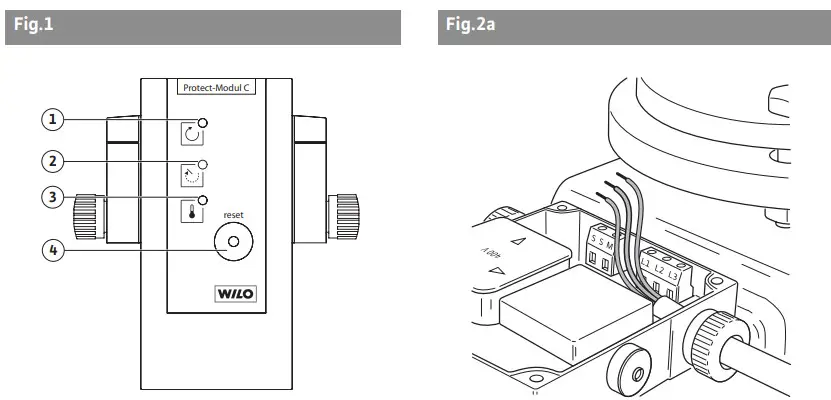
Variable differential pressure (Δp-v): The differential pressure setpoint levels being proportionally increased between ½H and H over the permissible flow range. The pump-generated differential pressure will thus be controlled to the respective level. The pump automatically responds to the night setback of the central heating installation by electronic evaluation from a temperature sensor. The pump will then switch to the minimum speed. On renewed boiler heat up the pump will switch back to the previously adjusted setpoint level. The night setback control can be switched off (Fig. 1, Item 2):
- auto: Night setback ON, control operation to the preselected setpoint value, and automatic, temperature-activated night setback (additional power savings).
 Night setback OFF, control operation to the preselected setpoint value.
Factory setting: Night setback OFF. NOTE:
NOTE:
In the case of insufficient heating/cooling capacity of the installation (too low a heat transfer), it must be checked whether the night setback control is on. In this case it must be switched off.
Faults, light signals, signal contacts
- Single pump
The following table shows the links between possible faults and the reactions of light signals and signal contacts:
Operating element | Status | Possible causes |
| Operation light signal green | off | • No supply voltage. • Control input “Ext. Off” opened. • Fault is present and has not yet been acknowledged. |
| flashing | • DP communication fault (only with a double pump). | |
| Fault signal light “Stoppage” red | off | • No motor stoppage. |
| on | • Motor stoppage recognised. • Mechanical blockage of pump • Winding fault | |
| flashing | • Motor stoppage acknowledged, the pump is in control loop 1). | |
| Fault signal light “Winding Overheat” red | off | • No overheating. |
| on | • Overheat recognized. • Pump overload • Winding fault • Unacceptable combination of medium temperature — ambient temperature | |
| flashing | • Overheat acknowledged, the pump is in control loop 1). | |
| Operating signal contact | open | • No supply voltage. • Control input “Ext. Off” opened. • Fault is present and has not yet been acknowledged. |
| closed | • Pump functioning, no-fault recognized. | |
| Fault signal contact | open | • Fault is present. • Pump is still in control loop 1). |
| closed | • Fault-free operation. | |
| Fault signal light “Stoppage” red | off | • No motor stoppage. |
| on | • Motor stoppage recognized. • Mechanical blockage of the pump. • Winding fault. |
- After acknowledging a fault, the Protect-Module C will be in a special control loop for up to 10 sec, depending on pump type and fault. If the fault is recognized again during this process, the pump returns to fault status.
Table 1
- Double pump:
The relationships between possible faults and the reactions of light signals and signal contacts depend on the following factors: - Parametrization of signal contacts in individual operation/individual fault signal or joint operation/collective fault signal (function see Table 2)
- Allocation of “Ext. Off” control inputs to master and slave
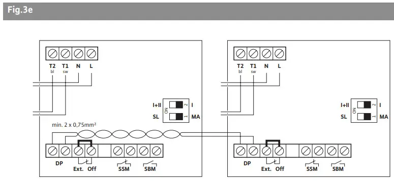
Double pump operation
A Protect-Module C must be installed for each of the two pumps.
The double pump functions on the Protect-Module C are:
- Main/Reserve operation with automatic switching to the standby reserve pump after 24 hours of real running time, the external control command “Ext. Off” interrupts the running time counter.
- Switching takes place through an overlap, i.e. at the time of switching, both pumps run simultaneously (for approx. 10 sec.). This avoids pressure surges and undersupplies in cooling and air-conditioning systems for example.
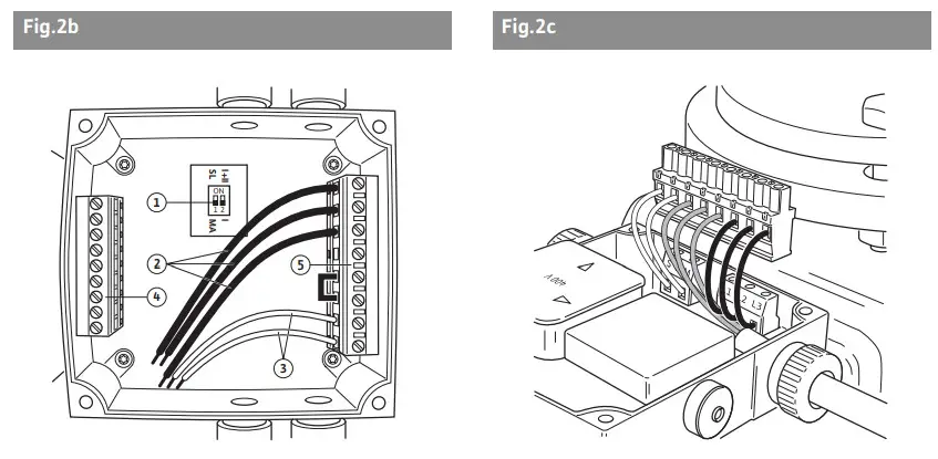
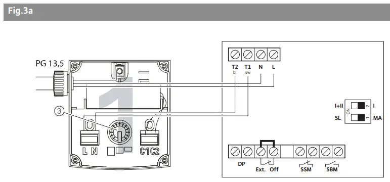
- The DIP switch 1 (figure 2b, position 1) determines which pump is the master (MA) and which pump is the slave (SL) (function see Table 2).
- The DIP switch 2 (figure 2b, position 1) determines whether the signal contacts “SSM” and “SBM” are individual or collective signals (function see Table 2).
- In the case of a fault in the working pump, the system switches to the standby pump after approx. 3 sec.
| Single pump | Double pump | |
| Master (MA) | Slave (SL) | |
| DIP Switch1: MA DIP Switch2: I Allocate terminals to Ext. Off | DIP Switch1: MA DIP Switch2: Allocate terminals to Ext. Off | DIP Switch1: SL DIP Switch2: Bridge terminals to Ext. Off |
| DIP Switch1: MA DIP Switch2: I SSM: Collective fault signal for pump | DIP Switch1: MA DIP Switch2: I SSM: Individual fault signal for MA DIP Switch2: I + II SSM: Collective fault signal for MA + SL | DIP Switch1: SL DIP Switch2: SSM: Individual fault signal for SL DIP Switch2: SSM: Individual fault signal for SL |
| DIP Switch1: MA DIP Switch2: I SBM: Individual operating signal for pump | DIP Switch1: MA DIP Switch2: I SBM: Individual operating signal for MA DIP Switch2: I + II SBM: Collective operating signal for MA + SL | DIP Switch1: SL DIP Switch2: SBM: Individual operating signal for SL DIP Switch2: SBM: Individual operating signal for SL |
Installation and electrical connection
Installation and electrical connection should be carried out in accordance with local regulations and only by qualified personnel!
Installation and the electrical connection must be carried out in accordance with local regulations and only by qualified personnel.![]() WARNING! The danger of personal injury
WARNING! The danger of personal injury
The applicable regulations on the prevention of accidents must be observed.![]() WARNING! The danger of electric shock
WARNING! The danger of electric shock
Potential dangers from electrical currents must be eliminated.
Local directives or general regulations [e.g. IEC, VDE, etc.] and those issued by the local power supply company must be adhered to.
Installation
- Install pump only after completion of all welding/soldering and after the pipe system had been thoroughly flushed out.
- Mount the pump in an easily accessible location in order to facilitate later inspections or exchanges.
- When installed in the flow pipe of an open-vented system, the safety vent must be connected to the inlet side of the pump.
- Isolating valves should be provided and installed at both the suction and discharge ports of the pump in order to facilitate a possible pump exchange. They must be located in such a way to prevent valve spindle leakage from spilling onto the control module (upper valve turned sideways).
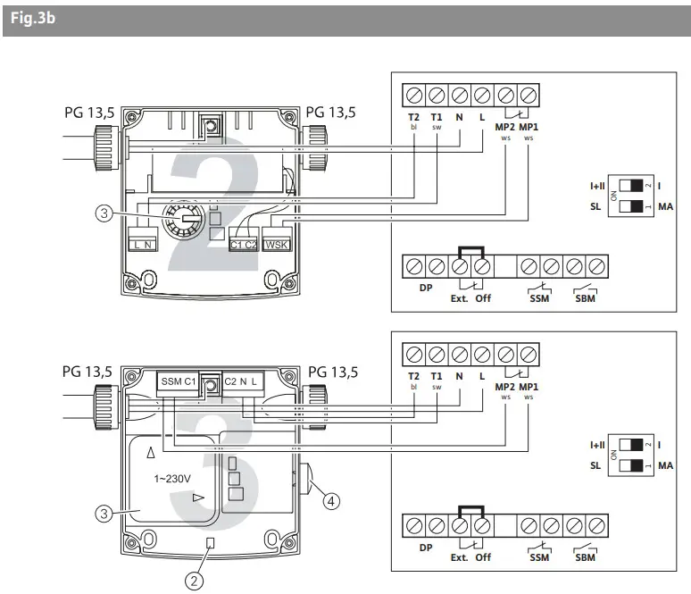
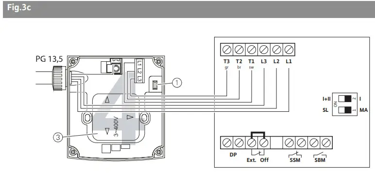
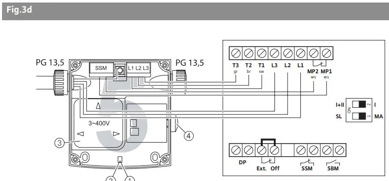
- Install pump free of stress and with the motor shaft horizontally located. For module, locations refer to Fig. 3. Other arrangements on request.
- Directional arrows on the pump body and the insulation shell indicate the direction of flow.
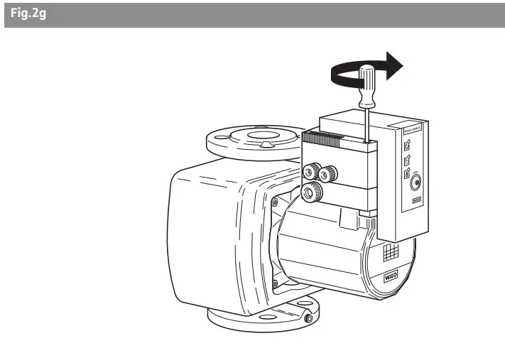
- If the mounting location of the module is to be altered, turn the motor housing as follows:
- Unclip the insulation shell with the aid of a screwdriver and remove,
- undo the 2 Allen screws,
- turn motor housing including control module.
 CAUTION! Risk of damage to the pump! When turning on the motor housing the gasket may be damaged. Replace damaged gaskets immediately. Size of gasket: ∅86 mm OD x ∅76 mm ID x2,0 mm thick, EP.
 - Reset and fix Allen screws,
- refit insulation shell.
Electrical connection![]() WARNING! Risk of electric shock! Electrical connection must be carried out by an electrical installer authorized by the local power supply company in accordance with the applicable local regulations.
WARNING! Risk of electric shock! Electrical connection must be carried out by an electrical installer authorized by the local power supply company in accordance with the applicable local regulations.
- The power supply must correspond to name plate data.
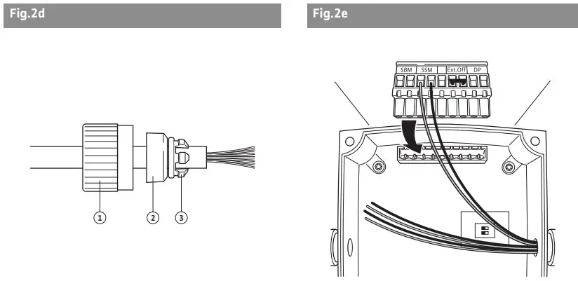
- Power wiring to be in accordance with Fig. 4:
- power connections: L, N, PE.
- max. line fuse: 10 A, slow action.
- The connecting cable can optionally be led through the cable gland on either right or left. The gland and the blank plug (PG 11) must then be changed.
- Strictly comply with local earthing regulations.
- All wiring and external switchgear to comply with local regulations (use of conduits, switch air gaps, and pole switches) in strict accordance with locally ruling regulations.
- The incoming power cable must be sufficiently large size to maintain protection from moisture ingress and to ensure a tight gland grip (e.g. H05W-F3G1,5 or AVMH-3×1,5).
- Heat-resisting cable must be used when installing the pump in systems with water temperatures above 90°C.
- Cable leads to be routed to avoid any contact with the adjoining pipework and/or the pump or motor housings.
Starting-up
WARNING! Risk of burning!
Note the acute danger of the pump becoming very hot, depending on the operating conditions of the pump or system respectively (fluid temperature). The danger of burning when touching the pump!
Initial start-up
Ensure that the pipe system is properly filled and air-vented. The pump rotor space is automatically vented after a short running period. Short-term dry running will not do harm to the pump. If, however, manual venting of the pump may become necessary (not apply to the air-venting pump) the following procedure is to be adopted:
- switch-off pump,
- close discharge isolating valve,WARNING! Risk of scalding! Depending on fluid temperature and system pressure there is the possibility of hot water in a liquid or gaseous state suddenly erupting under great force when opening the vent plug. Note the severe danger of scalding!
- break through the perforation, centrically the nameplate and open the vent screw carefully,
- protect electrical parts from released water,
- carefully move and push the pump shaft with a screwdriver,CAUTION! Risk of damage to the pump! There is the possibility, depending on the system pressure, of the pump jamming with the vent plug open. Before switching on the pump refit and tighten the vent plug.
- refit and tighten the vent plug,
- reopen the discharge valve,
- and switch on the pump.
Adjusting the pump capacity
- Select desired control mode (refer to chapter 6.1).
- Preselect pump capacity (head) at the dial button according to requirements (Fig. 1, Item 2).
- If head requirements are not known it is recommended to begin with a 1,5 m setting.
- If the heating capacity proves insufficient increase head setting step by step.
- Reduce heat setting step by step if the heating capacity is too high or noise generation is excessive.
- Select night setback mode; switch either to On or Off (refer to chapter 6.1).
Maintenance
Maintenance and repair work should only be carried out by qualified personnel!![]() WARNING! Risk of electric shock! Potential dangers caused by electrical energy must be excluded.
WARNING! Risk of electric shock! Potential dangers caused by electrical energy must be excluded.
- The pump must be switched off for all repair work and secured against unauthorized operation.
- In principle, damage to the connecting cable should only be repaired by a qualified electrician.
Problems, causes, and remedies
The pump is switched on but does not run:
- check electrical fuses,
- check voltage available at the pump (note nameplate data),
- Locked rotor:
- switch off the pump,
 WARNING! Risk of scalding! Depending on fluid temperature and system pressure there is the possibility of hot water in a liquid or gaseous state suddenly erupting under great force when opening the vent plug. Note the severe danger of scalding!
 - close isolating valves at both pump ports and letting the pump cool down. Remove the vent plug, check freedom of rotation and relock the pump rotor by turning the shaft at its slotted end with the aid of a screwdriver
- switch on the pump.
- Should the blockage not be automatically resolved via the automatic deblocking system, please consult the manual procedural instructions as described above.
Noisy pump operation
- check differential pressure setting and adjust respectively.
- Heating capacity too low, possibilities to increase:
- Stepp-up setpoint value,
- switch off night setback,
- To briefly switch off night setback mode (check on control operations) it is sufficient to just turn the dial button a little.
- On cavitation, increase system pressure within the permissible limit.
If no solution can be found, please contact your plumbing and heating specialist or your nearest Wilo Customer Service or representative.
Spare parts
Spare parts are ordered via a local specialist dealer and/or Wilo customer service. In order to avoid queries and incorrect orders, make sure to mention all data indicated on the rating plate when placing your order.
Subject to technical alterations!
Declaration of conformity
according to 2004/108/EC annex IV,2 and 2006/95/EC annex III, B,
Herewith, we declare that this product:
Stratos ECO
Stratos ECO Z
Stratos ECO L
Stratos ECO ST
Stratos ECO BMS
in its delivered state complies with the following relevant provisions:
Electromagnetic compatibility – directive
2004/108/EG
Low voltage directive
2006/95/EG
and with the relevant national legislation.
Applied harmonized standards, in particular:
EN 6035-2-51
EN 61000-6-2
EN 61000-6-3
If the above-mentioned series are technically modified without our approval, this declaration shall no longer be applicable.
 WILO SE
Nortkirchenstraße 100
44263 Dortmund
Germany
Wilo – International (Subsidiaries)
| Argentina WILO SALMSON Argentina S.A. C1295ABI Ciudad Autónoma de Buenos Aires T+ 54 11 4361 5929 [email protected] Austria WILO Pumpen Österreich GmbH 1230 Wien T +43 507 507-0 [email protected] Azerbaijan WILO Caspian LLC 1065 Baku T +994 12 5962372 [email protected] Belarus WILO Bel OOO 220035 Minsk T +375 17 2503393 [email protected] Belgium WILO SA/NV 1083 Ganshoren T +3224823333 [email protected] Bulgaria WILO Bulgaria Ltd. 1125 Sofia T +359 2 9701970 [email protected] Canada WILO Canada Inc. Calgary, Alberta T2A 5L4 T +1 403 2769456 [email protected] China WILO China Ltd. 101300 Beijing T +861058041888 [email protected] Croatia WILO Hrvatska d.o.o. 10090 Zagreb T +38 51 3430914 [email protected] Czech Republic WILO Praha s.r.o. 25101 Cestlice T +420 234 098711 [email protected] | Denmark WILO Danmark A/S 2690 Karlslunde T +45 70 253312 [email protected] Estonia WILO Eesti OÜ 12618 Tallinn T +372 6509780 [email protected] Finland WILO Finland OY 02330 Espoo T +358 207401540 [email protected] France WILO S.A.S. 78390 Bois d’Arcy T +33 1 30050930 [email protected] Great Britain WILO (U.K.) Ltd. DE14 2WJ BurtonUpon-Trent T +44 1283 523000 [email protected] Greece WILO Hellas AG 14569 Anixi (Attika) T +302 10 6248300 [email protected] Hungary WILO Magyarország Kft 2045 Törökbálint (Budapest) T +36 23 889500 [email protected] India WILO India Mather and Platt Pumps Ltd. Pune 411019 T +91 20 27442100 service@pun. matherplatt.co.in Indonesia WILO Pumps Indonesia Jakarta Selatan 12140 T +62 21 7247676 [email protected] | Ireland WILO Engineering Ltd. Limerick T +353 61 227566 [email protected] Italy WILO Italia s.r.l. 20068 Peschiera Borromeo (Milano) T +39 25538351 [email protected] Kazakhstan WILO Central Asia 050002 Almaty T +7 727 2785961 [email protected] Korea WILO Pumps Ltd. 621-807 Gimhae Gyeongnam T +82 55 3405890 [email protected] Latvia WILO Baltic SIA 1019 Riga T +371 67 145229 [email protected] Lebanon WILO SALMSON Lebanon 12022030 El Metn T +961 4 722280 [email protected] Lithuania WILO Lietuva UAB 03202 Vilnius T +370 5 2136495 [email protected] The Netherlands WILO Nederland b.v. 1551 NA Westzaan T +31 88 9456 000 [email protected] Norway WILO Norge AS 0975 Oslo T +47 22 804570 [email protected] Poland WILO Polska Sp. z.o.o. 05-090 Raszyn T +48 22 7026161 [email protected] | Portugal Bombas Wilo-Salmson Portugal Lda. 4050-040 Porto T +351 22 2080350 [email protected] Romania WILO Romania s.r.l. 077040 Com. Chiajna Jud. Ilfov T +40 21 3170164 [email protected] Russia WILO Rus ooo 123592 Moscow T +7 495 7810690 [email protected] Saudi Arabia WILO ME – Riyadh Riyadh 11465 T +966 1 4624430 [email protected] Serbia and Montenegro WILO Beograd d.o.o. 11000 Beograd T +381112851278 [email protected] Slovakia WILO Slovakia s.r.o. 82008 Bratislava 28 T +421 2 45520122 [email protected] Slovenia WILO Adriatic d.o.o. 1000 Ljubljana T +38615838130 [email protected] South Africa Salmson South Africa 1610 Edenvale T +27 11 6082780 errol.cornelius@ salmson.co.za Spain WILO Ibérica S.A. 28806 Alcalá de Henares (Madrid) T +34 91 8797100 [email protected] | Sweden WILO Sverige AB 35246 Växjö T +46 470 727600 [email protected] Switzerland EMB Pumpen AG 4310 Rheinfelden T +41 61 83680-20 [email protected] Taiwan WILO-EMU Taiwan Co. Ltd. 110 Taipeh T +886 227 391655 nelson.wu@ wiloemutaiwan.com.tw Turkey WILO Pompa Sistemleri San. ve Tic. A.S¸. 34530 Istanbul T +90 216 6610211 [email protected] Ukraina WILO Ukraina t.o.w. 01033 Kiew T +38 044 2011870 [email protected] United Arab Emirates WILO Middle East FZE Jebel Ali – Dubai T +971 4 8864771 [email protected] USA WILO-EMUUSA LLC Thomasville, Georgia 31792 T +1 229 5840097 [email protected] WILO USA LLC Melrose Park, Illinois 60160 T +1708 3389456 [email protected] Vietnam WILO Vietnam Co Ltd. Ho Chi Minh City, Vietnam T +84 8 38109975 [email protected] |
Wilo – International (Representation offices)
| Algeria Bad Ezzouar, Dar El Beida T +213 21 247979 Armenia 375001 Yerevan T +374 10 544336 Bosnia and Herzegovina 71000 Sarajevo T +387 33 714510 | Georgia 0179 Tbilisi T +995 32 306375 Macedonia 1000 Skopje T +389 2 3122058 Mexico 07300 Mexico T +52 55 55863209 | Moldova 2012 Chisinau T +373 2 223501 Rep. Mongolia Ulaanbaatar T +976 11 314843 Tajikistan 734025 Dushanbe T +992 37 2232908 | Turkmenistan 744000 Ashgabad T +993 12 345838 Uzbekistan 100015 Tashkent T +998 71 1206774 |
WILO SE
Nortkirchenstraße 100
44263 Dortmund
Germany
T 0231 4102-0
F 0231 4102-7363
[email protected]
www.wilo.de


