Wilo TOP-Z 40-7 230 V Hot Water Circulator Pump Instruction Manual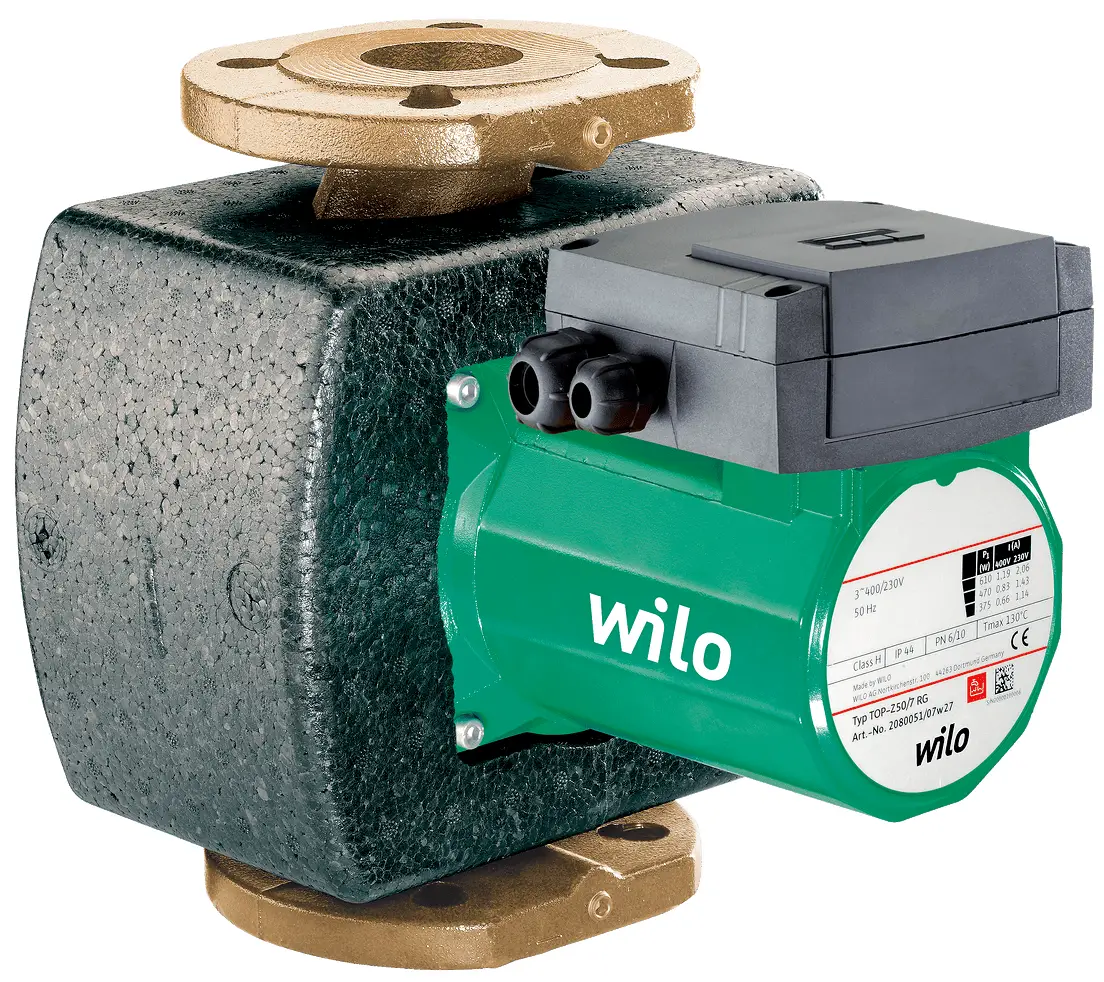
General
About this document
These Installation and Operating Instructions are an integral part of the product.
They must be kept readily available at the place where the product is installed.
Strict adherence to these instructions is a precondition for the proper use and correct operation of the product.
These Installation and Operating Instructions correspond to the relevant version of the product and the underlying safety standards valid at the time of going to print.
These Installation and operating instructions are an addition to the Installation and operating instructions for glandless circulation pump type TOP-S/ TOP-SD/TOP-Z.
Safety
These operating instructions contain basic information which must be adhered to during installation and operation. For this reason, these operating instructions must, without fail, be read by the service technician and the responsible operator before installation and commissioning .
It is not only the general safety instructions listed under the main point “safety” that must be adhered to but also the special safety instructions with danger symbols included under the following main points.
Designation of information in the operating instructions
Symbols:
![]() General danger symbol
General danger symbol
![]() Danger due to electrical voltage
Danger due to electrical voltage
![]() NOTE: …
NOTE: …
Signal words:
DANGER!
Acutely dangerous situation.
Non-observance results in death or the most serious of injuries.
WARNING!
The user can suffer (serious) injuries. ‘Warning’ implies that (serious) injury to persons is probable if this information is disregarded.
CAUTION!
There is a risk of damaging the pump/unit. ‘Caution’ implies that damage to the product is likely if the information is disregarded.
NOTE:
Useful information on using the product. It draws attention to possible problems.
Personnel qualifications
The installation personnel must have the appropriate qualification for this work.
Danger in event of non-observance of the safety instructions
Non-observance of the safety instructions can result in risk of injury to persons and damage to pump/unit. Non-observance of the safety instructions can result in the loss of any claims to damages.
In detail, non-observance can, for example, result in the following risks:
- Failure of important pump/unit functions,
- Failure of required maintenance and repair procedures
- Danger to persons from electrical, mechanical and bacteriological influences,
- Property damage
Safety instructions for the operator
The existing directives for accident prevention must be adhered to.
Danger from electrical current must be eliminated. Local directives or general directives [e.g. IEC, VDE etc.] and local power supply companies must be adhered to.
Safety instructions for inspection and installation work
The operator must ensure that all inspection and installation work is carried out by authorised and qualified personnel, who are sufficiently informed from their own detailed study of the operating instructions.
Work to the pump/unit must only be carried out when at a standstill.
Unauthorised alteration and spare part production
Alterations to the pump/unit are only permissible after consultation with the manufacturer. Original spare parts and accessories authorised by the manufacturer ensure safety. The use of other parts can nullify the liability from the results of their usage.
Unacceptable operating modes
The operating safety of the supplied pump/unit is only guaranteed for conventional use in accordance with Section 4 of the operating instructions. The limit values must on no account fall under or exceed those specified in the catalogue/ data sheet.
Transport and interim storage
On receipt of the product, check it for any damage incurred in transit. In the event of damage in transit, the necessary steps must be taken with the carrier before the relevant deadlines.
![]() CAUTION! Danger of damage to the module!
CAUTION! Danger of damage to the module!
Danger of damage due to improper handling during transport and storage.
- The Protect-Module C must be protected during transport and storage from moisture, frost and mechanical damage.
- It must not be exposed to any temperature outside the range – 10 °C to + 70 °C.
Application
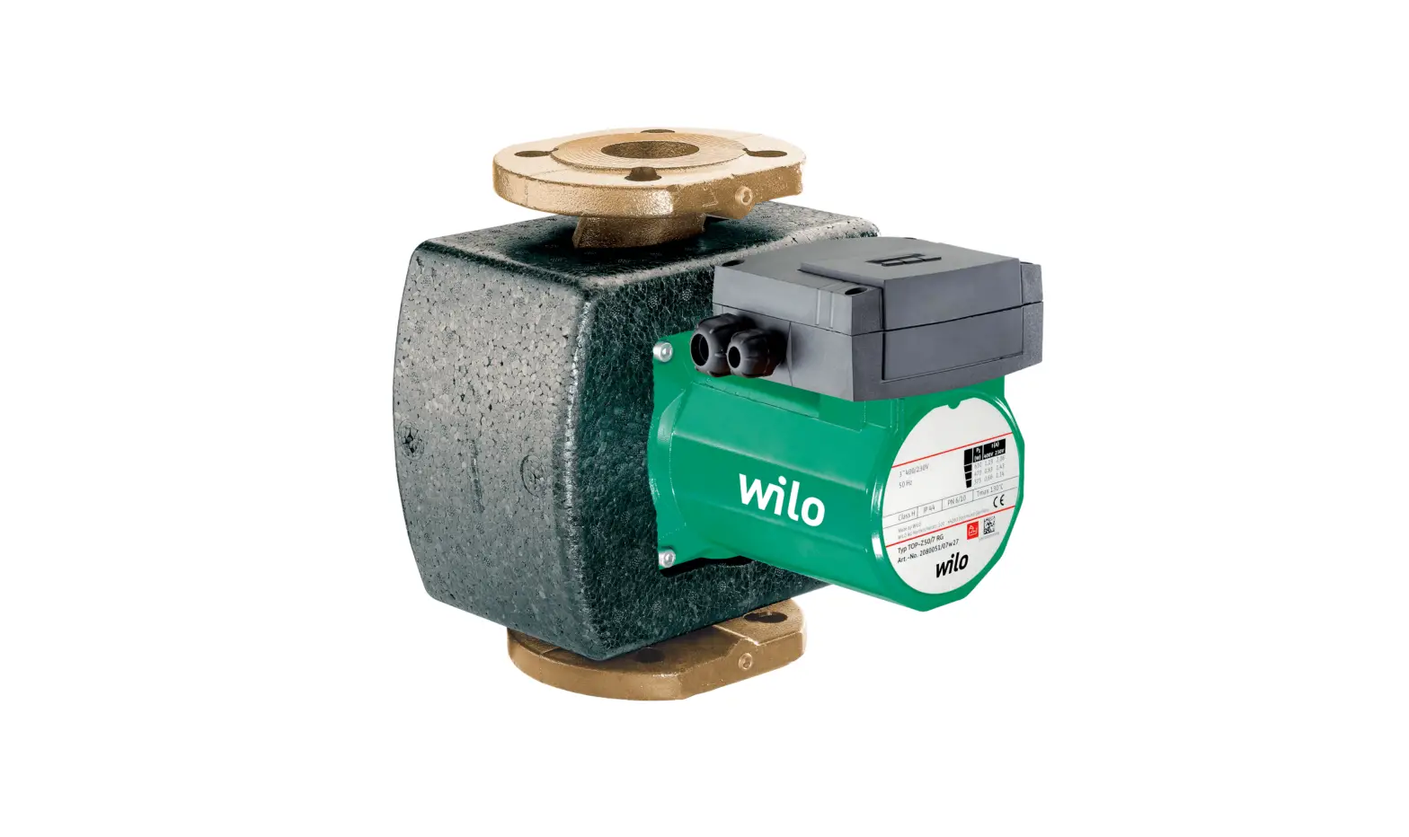
The TOP series circulating pumps come equipped with a standard terminal box.
A retrofit plug-in module is available for the pump with the Protect-Module C (see title illustration). In addition to the pump functions, the Protect-Module C also enables further signals as well as the performance of control tasks.
When the Protect-Module C is deployed, external contactors and supplementary switchgears are no longer required, with a corresponding effect on the complexity of the installation.
Product data
Type Key
| Example: Wilo-Protect-Modul C Type 22 EM | |
| Protect-Modul | Series designation |
| C | Comfort |
| Type 22 | Type designation: 22 or 32-52 |
| EM | For mains connection: EM = 1~230 V, 50 Hz (single-phase motor) DM = 3~400 V, 50 Hz (three-phase current motor) |
Technical data
| Technical data | |
| Connection current Type 22 EM Type 32-52 EM Type 22 DM Type 32-52 DM | 1~230 V, ±10 %, 50 Hz 1~230 V, ±10 %, 50 Hz 3~400 V, ±10 %, 50 Hz 3~400 V, ±10 %, 50 Hz |
| Frequency | 50 Hz |
| Terminal cross-section, all terminals | max. 2.5 mm2 |
| Temperature range of flow medium | -20 °C to +110 °C |
| Max. ambient temperature | +40 °C |
| Pump protection class | IP 44 |
| Cable connections | 4x PG9 |
| Electromagnetic compatibility: Emitted interference Immunity to interference | EN 61000-6-3 EN 61000-6-2 |
Scope of supply
- Protect-Module C
- Plug strip control and signal terminals
- Plug strip mains connection terminals and connection terminals WSK/SSM with connection cables
- Fixing screws (4)
- Installation and operating instructions
Description and function
Description of the Protect-Module C
The functions of the pump housed in the terminal box (mains connection, thermal winding contact WSK or potential-free collective fault signal) are transferred to the terminal box when the Protect-Module C is installed. The fault acknowledgement button and the direction of rotation control lamp, if fitted, as well as the manual speed stage switching of the standard terminal box continue to function when the Protect-Module C is installed.
The Protect-Module C is fitted to the standard terminal box of the pump in place of the terminal box cover.
Functions and operation of the Protect-Module C
Light signals
There are three possible light signals on the display field:
- Operation light signal (figure 1, position 1)
 WARNING! Danger of electric shock
Even when the operation light signal is off, voltage may be present on the Protect-Module. - Fault signal light “Stoppage” (figure 1, position 2)
- Fault signal light “Winding Overheat” (figure 1, position 3)

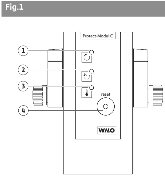
Fault acknowledgement buttons
- Fault acknolwledgement button on the pump (figures 3b, 3d, position 4) If fitted, this button is used to reset the response of the integrated full motor protection. This fault reset is done before fault reset on the Protect Module C.


- Fault acknowledgement button on Protect-Module C (figure 1, position 4)
- A fault displayed on the Protect-Module C is reset by briefly pressing this button (< 1s).
- Pressing and holding down the button (≥ 1s) triggers pump cycling in dual pump operation with integrated dual pump management.
Faults, light signals, signal contacts
- Single pump
The following table shows the links between possible faults and the reactions of light signals and signal contacts:
Table 1
| Operating element | Status | Possible causes |
| Operation light signal green | off |
|
| flashing |
| |
| Fault signal light “Stoppage” red | off |
|
| on |
| |
| flashing |
| |
| Fault signal light “Winding Overheat” red | off |
|
| on |
| |
| flashing |
| |
| Operating signal contact | open |
|
| closed |
| |
| Fault signal contact | open |
|
| closed |
| |
| Fault signal light “Stoppage” red | off |
|
| on |
|
- After acknowledging a fault, the Protect-Module C will be in a special control loop for up to 10 sec, depending on pump type and fault. If the fault is recognised again during this process, the pump returns to fault status.
- Double pump:
The relationships between possible faults and the reactions of light signals and signal contacts depend on the following factors: - Parametrisation of signal contacts in individual operation/individual fault signal or joint operation/collective fault signal (function see Table 2)
- Allocation of “Ext. Off” control inputs to master and slave
Double pump operation
A Protect-Module C must be installed for each of the two pumps.
The double pump functions on the Protect-Module C are:
- Main/Reserve operation with automatic switching to the standby reserve pump after 24 hours of real running time, the external control command “Ext. Off” interrupts the running time counter.
- Switching takes place through an overlap, i.e. at the time of switching, both pumps run simultaneously (for approx. 10 sec.). This avoids pressure surges and undersupply in cooling and air-conditioning systems for example.
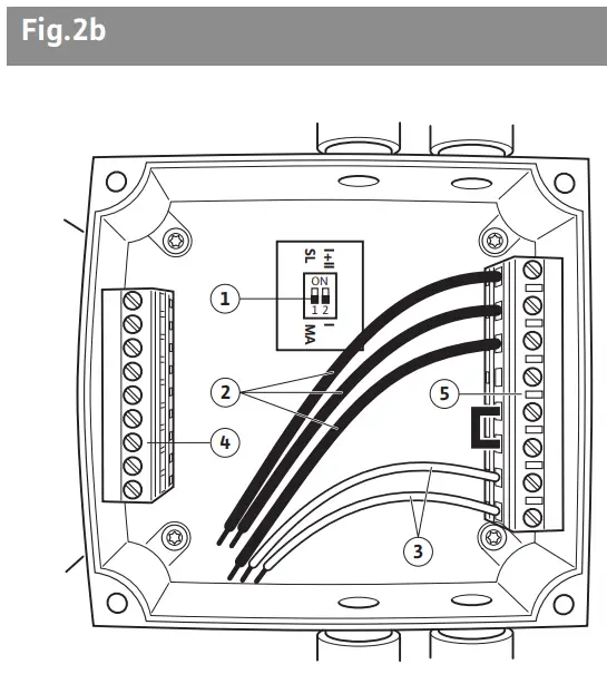
- The DIP switch 1 (figure 2b, position 1) determines which pump is the master (MA) and which pump is the slave (SL) (function see Table 2).
- The DIP switch 2 (figure 2b, position 1) determines whether the signal contacts “SSM” and “SBM” are individual or collective signals (function see Table 2).
- In the case of a fault in the working pump, the system switches to the standby pump after approx. 3 sec.
Table 2
| Single pump | Double pump | |||
| Master (MA) | Slave (SL) | |||
| DIP Switch1: MA DIP Switch2: I Allocate terminals to Ext. Off | DIP Switch1: MA DIP Switch2: – Allocate terminals to Ext. Off | DIP Switch1: SL DIP Switch2: – Bridge terminals to Ext. Off | ||
| DIP Switch1: MA DIP Switch2: I SSM: Collective fault signal for pump | DIP Switch1: MA DIP Switch2: I SSM: Individual fault signal for MA DIP Switch2: I + II SSM: Collective fault signal for MA + SL | DIP Switch1: SL DIP Switch2: – SSM: Individual fault signal for SL DIP Switch2: – SSM: Individual fault signal for SL | ||
| DIP Switch1: MA DIP Switch2: I SBM: Individual operating signal for pump | DIP Switch1: MA DIP Switch2: I SBM: Individual operating signal for MA DIP Switch2: I + II SBM: Collective operating signal for MA + SL | DIP Switch1: SL DIP Switch2: – SBM: Individual operating signal for SL DIP Switch2: – SBM: Individual operating signal for SL | ||
| – : Setting of DIP switch not relevant | ||||
Installation and electrical connection
Installation and electrical connection must be carried out in accordance with local regulations and only by qualified personnel.![]() WARNING! Danger of personal injury
WARNING! Danger of personal injury
The applicable regulations on the prevention of accidents must be observed.![]() WARNING! Danger of electric shock
WARNING! Danger of electric shock
Potential dangers from electrical currents must be eliminated.
Local directives or general regulations [e.g. IEC, VDE etc.] and those issued by the local power supply company must be adhered to.
Installation and electrical connection of mains cable
- Switch off power supply to pump, CAUTION! Danger of damage to Protect-Module C
The module may only be plugged in and unplugged when the pump has been completely disconnected. - Loosen the terminal box lid screws on the pump,
- Remove terminal box lid,
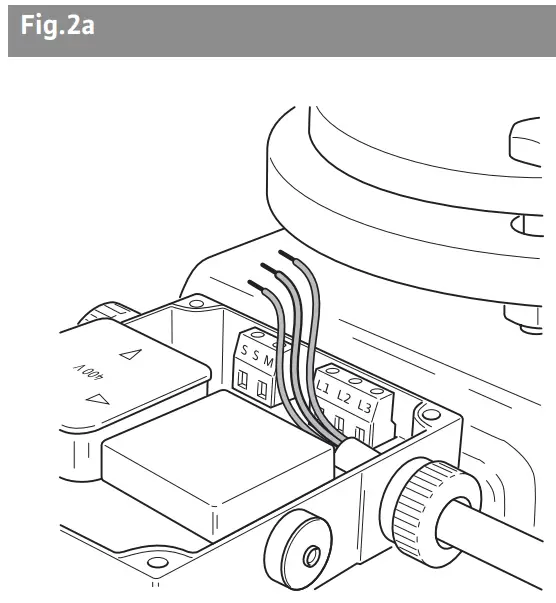
- Pinch off power supply cable except the protective lead PE:
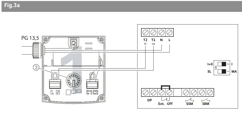
EM version (1~230V): L, N
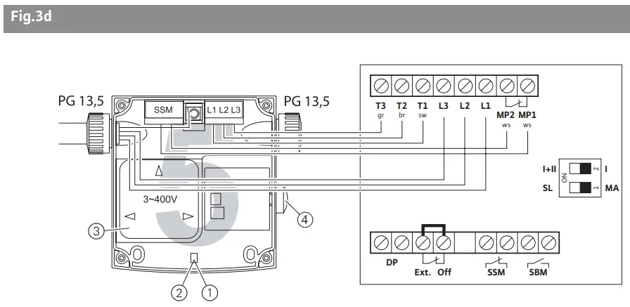
DM version (3~400V) L1, L2, L3 (figure 2a)
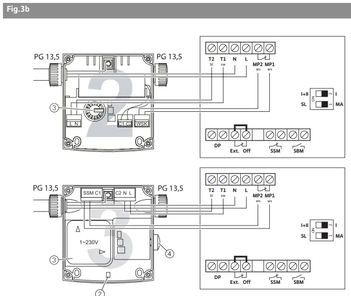
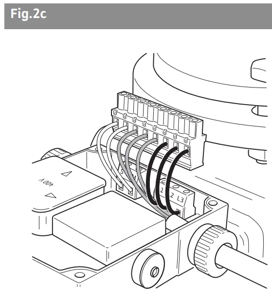
- Remove plug strip with power supply terminals and connection terminals MP1/MP2 (figure 2b, position 5) with connection cables (figure 2b, position. 2.3) from the Protect-Module C. When removing, do not pull straight out, but begin at one corner of the plug strip,

- Apply the plug strip cables to the corresponding terminals on the pump terminal box (figure 2c, figure 3),


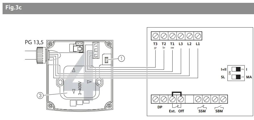
- Fit power supply cable to the plug strip, Table 3 shows the allocation of module types to the terminal diagrams.
Table 3Protect-Module C Terminal diagram Type 22 EM
Type 32-52 EM
Type 22 DM
Type 32-52 DM3a
3b
3c
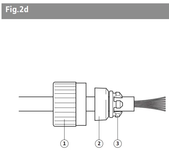
3d - Remove the plug strip with control and signal terminals (figure 2b, position 4) from the Protect-Module C. When removing, do not pull straight out, but begin at one corner of the plug strip,
- Dismantle cable connection (PG 9) of the Protect-Module C,
- Cut diaphragm seal,
- Thread individual parts of the cable connection onto the control cable (figure 2d),

Pos. 1: Union connection
Pos. 2: Seal
Pos. 3: Strain relief - Insert control cable through cable connection into Protect Module C,
- Assemble cable connection, fastening union nuts tightly enough so that the cable can no longer be pulled out of the cable connection by handCAUTION! Danger of damage to Protect-Module C
An incorrectly assembled cable connection may lead to a short circuit in the module due to water penetration. This is a particular danger in cold water installations in which condensation constantly forms.
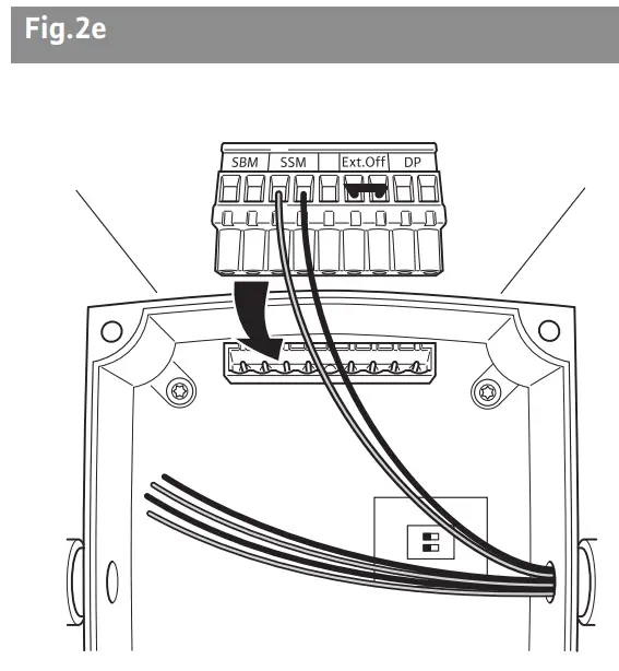
- Fix control cable to the plug strip (figure 2 e),

- Plug the plug strip with control cable to the corresponding place in the Protect-Module C,
- Set DIP switch (figure 2b, position 1) in accordance with Table 2,
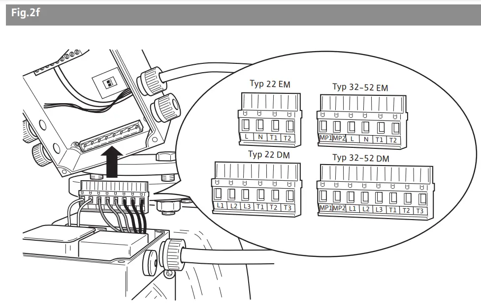
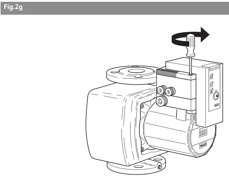
- Plug the Protect-Module C on to the plug strip with the power connections (figure 2f),

Note: Arrange power cables and leads so that they cannot be crushed when finally tightening the module installation.
In DM versions, it is essential before final tightening of the module installation to check the direction of rotation with the direction of rotation control lamp in the pump terminal box (figures 3c, 3d, position 1).
- Arrange the Protect-Module C over the terminal box structure and screw to the domes of the terminal box using the screws provided, tighten screws evenly diagonally (figure 2g).

- Stages 1 to 4 are not required for a new installation. Power connection is made directly on the corresponding plug strip with power connection terminals and connection terminals MP1/MP2.
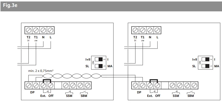
- For a double pump, as previously described, two Protect-Modules C must be fitted. For integrated dual pump management, the DP terminals of the two Protect-Modules C must be connected to each other, see also figure 3e.
Electrical connection of control and signal clamps
For connection to a remote control centre or building automation, the following connections are provided:
- Ext. Off: Control input with “drive priority off” for potential-free normally closed contacts, contact charge 24V, 10 mA.
In dual pump operation, Ext. Off on the master must be assigned to a potentialfree normally closed contact, and Ext. Off on the slave must remain bridged. The Ext. Off of the master works on the entire double pump, i.e. master and slave. - SBM: Programmable run signal, potential-free normally opened contact, maximum contact capacity 250 VAC, 1 A.
- SSM: Programmable fault signal, potential-free normally closed contact, maximum contact capacity 250 VAC, 1 A.
A serial interface is provided for integrated dual pump management: - DP: Interface for integrated dual pump management, the connection terminals cannot be twisted. The connection cable (2 x 0/75 mm2 ) must be provided on site. Wiring for all Protect-Modules is shown in the example in figure 3e.
Commissioning
![]() CAUTION! Danger of damage to Protect-Module C
CAUTION! Danger of damage to Protect-Module C
When commissioning, the Installation and operating instructions of the glandless circulation pump, types TOP-S/TOP-SD/TOP-Z must be observed.![]() NOTE: Rotation control (only for three-phase motors)
NOTE: Rotation control (only for three-phase motors)
In pumps with three-phase connection, before final tightening of the module installation, it is essential to check the direction of rotation with the direction of rotation control lamp in the pump terminal box (figures 3c, 3d, position 1).
- When the Protect-Module C is fully installed, switch on power supply.
Maintenance
Maintenance and repair work must only be carried out by professionally qualified personnel.![]() WARNING! Danger of electric shock
WARNING! Danger of electric shock
Potential dangers from electrical currents must be eliminated.
During all maintenance and repair work, the pump must be disconnected from the power supply and secured against possible unauthorised reconnection.
Faults, causes and remedies
If an operating fault of the pump / the Protect-Module C / system cannot be corrected, please consult a professional technician or contact your nearest Wilo Customer Service point or representative.
Spare parts
Spare parts may be ordered through local professional technicians and/or Wilo Customer Service.
To avoid queries and order errors, all data on the rating plate must be given along with every order.
Subject to technical changes!
Wilo – International (Subsidiaries)
Austria
WILO Handelsges. m.b.H.
1230 Wien
T +43 1 25062-0
F +43 1 25062-15
[email protected]
Belarus
WILO Bel OOO
220035 Minsk
T +375 17 2503383
[email protected]
Belgium
WILO NV/SA
1083 Ganshoren
T +32 2 4823333
F +32 2 4823330
[email protected]
Bulgaria
WILO Bulgaria EOOD
1125 Sofia
T +359 2 9701970
F +359 2 9701979
[email protected]
Canada
WILO Canada Inc.
Calgary, Alberta T2A5L4
T +1 403 2769456
F +1 403 2779456
[email protected]
China
WILO SALMSON (Beijing)
Pumps System Ltd.
101300 Beijing
T +86 10 804939700
F +86 10 80493788
[email protected]
Czech Republic
WILO Praha s.r.o.
25101 Cestlice
T +420 234 098 711
F +420 234 098 710
[email protected]
Denmark
WILO Danmark A/S
2690 Karlslunde
T +45 70 253312
F +45 70 253316
[email protected]
Finland
WILO Finland OY
02320 Espoo
T +358 9 26065222
F +358 9 26065220
[email protected]
France
WILO S.A.S.
78310 Coignières
T +33 1 30050930
F +33 1 34614959
[email protected]
Great Britain
WILO SALMSON Pumps Ltd.
DE14 2WJ Burton-on-Trent
T +44 1283 523000
F +44 1283 523099
[email protected]
Greece
WILO Hellas AG
14569 Anixi (Attika)
T +30 10 6248300
F +30 10 6248360
[email protected]
Hungary
WILO Magyarország Kft
1144 Budapest XIV
T +36 1 46770-70 Sales Dep.
46770-80 Tech. Serv.
F +36 1 4677089
[email protected]
Ireland
WILO Engineering Ltd.
Limerick
T +353 61 227566
F +353 61 229017
[email protected]
Italy
WILO Italia s.r.l.
20068 Peschiera Borromeo
(Milano)
T +39 02 5538351
F +39 02 55303374
[email protected]
Kazakhstan
TOO WILO Central Asia
480100 Almaty
T +7 3272 507333
F +7 3272 507332
[email protected]
Korea
WILO Industries Ltd.
137-818 Seoul
T +82 2 34716600
F +82 2 34710232
[email protected]
Latvia
WILO Baltic SIA
1019 Riga
T +371 7 145229
F +371 7 145566
[email protected]
Lebanon
WILO SALMSON
Lebanon s.a.r.l.
12022030 El Metn
T +961 4 722280
F +961 4 722285
[email protected]
Lithuania
UAB WILO Lietuva
03202 Vilnius
T +370 2 236495
F +370 2 236495
[email protected]
The Netherlands
WILO Nederland b.v.
1948 RC Beverwijk
T +31 251 220844
F +31 251 225168
[email protected]
Norway
WILO Norge A/S
0901 Oslo
T +47 22 804570
F +47 22 804590
[email protected]
Poland
WILO Polska Sp. z.o.o.
05-090 Raszyn k/Warszawy
T +48 22 7201111
F +48 22 7200526
[email protected]
Portugal
Bombas Wilo-Salmson
Portugal
4050-040 Porto
T +351 22 2080350
F +351 22 2001469
[email protected]
Romania
WILO Romania s.r.l.
7000 Bucuresti
T +40 21 4600612
F +40 21 4600743
[email protected]
Russia
WILO Rus o.o.o.
123592 Moskau
T +7 095 7810690
F +7 095 7810691
[email protected]
Serbia & Montenegro
WILO Beograd d.o.o.
11000 Beograd
T +381 11 765871
F +381 11 3292306
[email protected]
Slovakia
WILO Slovakia s.r.o.
82008 Bratislava 28
T +421 2 45520122
F +421 2 45246471
[email protected]
Slovenia
WILO Adriatic d.o.o.
1000 Ljubljana
T +386 1 5838130
F +386 1 5838138
[email protected]
Spain
WILO Ibérica S.A.
28806 Alcalá de Henares
(Madrid)
T +34 91 8797100
F +34 91 8797101
[email protected]
Sweden
WILO Sverige AB
35033 Växjö
T +46 470 727600
F +46 470 727644
[email protected]
Switzerland
EMB Pumpen AG
4310 Rheinfelden
T +41 61 8368020
F +41 61 8368021
[email protected]
Turkey
WILO Pompa Sistemleri
San. ve Tic. A.S¸.
34530 Istanbul
T +90 216 6610211
F +90 216 6610214
[email protected]
Ukraina
WILO Ukraina t.o.w.
01033 Kiew
T +38 044 2011870
F +38 044 2011877
[email protected]
USA
WILO USA LLC
Calgary, Alberta T2A5L4
T +1 403 2769456
F +1 403 2779456
[email protected]
Wilo – International (Representation offices)
Azerbaijan
370141 Baku
T +994 50 2100890
F +994 12 4975253
[email protected]
Bosnia and Herzegovina
71000 Sarajevo
T +387 33 714511
F +387 33 714510
[email protected]
Croatia
10000 Zagreb
T +385 1 3680474
F +385 1 3680476
[email protected]
Georgia
38007 Tbilisi
T/F +995 32 536459
[email protected]
Macedonia
1000 Skopje
T/F +389 2122058
[email protected].
Moldova
2012 Chisinau
T/F +373 22 223501
[email protected]
Tajikistan
734025 Dushanbe
T +992 372 316275
[email protected]
Uzbekistan
700029 Taschkent
T/F +998 71 1206774
[email protected]
Wilo-Vertriebsbüros
G1 Nord
WILO AG
Vertriebsbüro Hamburg
Sinstorfer Kirchweg 74–92
21077 Hamburg
T 040 5559490
F 040 55594949
G2 Ost
WILO AG
Vertriebsbüro Berlin
Juliusstraße 52–53
12051 Berlin-Neukölln
T 030 6289370
F 030 62893770
G3 Sachsen/Thüringen
WILO AG
Vertriebsbüro Dresden
Frankenring 8
01723 Kesselsdorf
T 035204 7050
F 035204 70570
G4 Südost
WILO AG
Vertriebsbüro München
Landshuter Straße 20
85716 Unterschleißheim
T 089 4200090
F 089 42000944
G5 Südwest
WILO AG
Vertriebsbüro Stuttgart
Hertichstraße 10
71229 Leonberg
T 07152 94710
F 07152 947141
G6 Rhein-Main
WILO AG
Vertriebsbüro Frankfurt
An den drei Hasen 31
61440 Oberursel/Ts.
T 06171 70460
F 06171 704665
G7 West
WILO AG
Vertriebsbüro Düsseldorf
Hans-Sachs-Straße 4
40721 Hilden
T 02103 90920
F 02103 909215
G8 Nordwest
WILO AG
Vertriebsbüro Hannover
Ahrensburger Straße 1
30659 Hannover-Lahe
T 0511 438840
F 0511 4388444
Zentrale Auftragsbearbeitung für den Fachgroßhandel
WILO AG
Auftragsbearbeitung
Nortkirchenstraße 100
44263 Dortmund
T 0231 4102-0
F 0231 4102-7555
Wilo-Kompetenz-Team
- Antworten auf alle Fragen rund um das Produkt, Lieferzeiten, Versand, Verkaufspreise
- Abwicklung Ihrer Aufträge
- Ersatzteilbestellungen – mit 24-Stunden-Lieferzeit für alle gängigen Ersatzteile
- Versand von Informationsmaterial
T 01805 R•U•F•W•I•L•O*
7•8•3•9•4•5•6
F 0231 4102-7666
Werktags erreichbar
von 7–18 Uhr
Wilo-Kundendienst
WILO AG
Wilo-Service-Center
Nortkirchenstraße 100
44263 Dortmund
- Kundendienststeuerung
- Wartung und Inbetriebnahme
- Werksreparaturen
- Ersatzteilberatung
T 01805 W•I•L•O•K•D*
9•4•5•6•5•3
0231 4102-7900
F 0231 4102-7126
Werktags erreichbar von
7–17 Uhr, ansonsten
elektronische Bereitschaft mit
Rückruf-Garantie!
Wilo-International
Österreich
Zentrale Wien:
WILO Handelsgesellschaft mbH
Eitnergasse 13
1230 Wien
T +43 1 25062-0
F +43 1 25062-15
Vertriebsbüro Salzburg:
Gnigler Straße 56
5020 Salzburg
T +43 662 8716410
F +43 662 878470
Vertriebsbüro
Oberösterreich:
Trattnachtalstraße 7
4710 Grieskirchen
T +43 7248 65051
F +43 7248 65054
Schweiz
EMB Pumpen AG
Gerstenweg 7
4310 Rheinfelden
T +41 61 8368020
F +41 61 8368021
Standorte weiterer
Tochtergesellschaften
Belarus, Belgien, Bulgarien,
China, Dänemark,
Finnland, Frankreich,
Griechenland,
Großbritannien,Irland,
Italien, Kanada,
Kasachstan, Korea,
Libanon, Litauen, Lettland,
Niederlande, Norwegen,
Polen, Rumänien,
Russland, Schweden,
Serbien & Montenegro,
Slowakei, Slowenien,
Spanien, Tschechien,
Türkei, Ukraine, Ungarn
Die Adressen finden Sie unter www.wilo.de oder www.wilo.com.
Stand März 2005
* 12 Cent pro Minute
WILO AG
Nortkirchenstraße 100
44263 Dortmund
Germany
T 0231 4102-0
F 0231 4102-7363
[email protected]
www.wilo.de