AIRWAVE TECHNOLOGIES AT-4200 Wireless Microphone Systems User Guide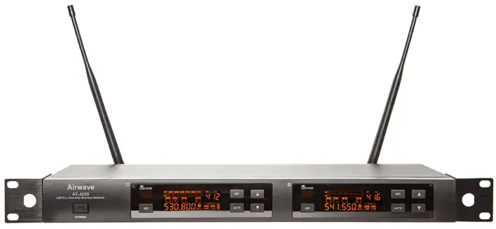
Introduction
Thank you for purchasing the Airwave Technologies AT-4200 wireless system. The AT-4000 series system has 9 groups with 16 channels per group for a total of 144 channels that can be used in a variety of ways including live performances, public speaking, entertainment venues, or the recording arts. All AT-4000 series components feature feather-touch buttons and LCD screens to facilitate quick and easy settings.
System Components
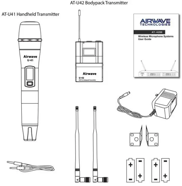
AT-4200 System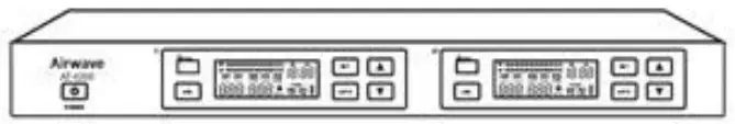
- AT-4200 Receiver
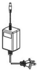
- Power Adapter
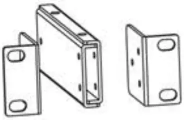
- Rack Panel
- Two Antenna
- One 1/4“ Audio Cable
- Four 1.IV “AA” Batteries
- User Manual

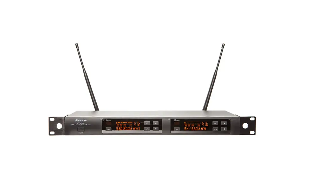
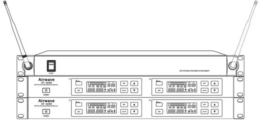
AT-4200 Receiver Front Panel Features
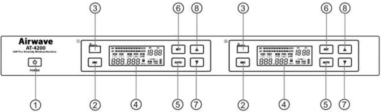
- Power Button – Press for 2 seconds to turn on, hold longer to turn off.
- ASC“ Infrared Frequency Button – Press this button to establish infrared connection between the receiver and the transmitter.
- Infrared Frequency “IR” Window
- LED Display
- Auto Button for Fast Frequency Sweep
- Set Button – To set all functions showing on the screen.
- Quick Up and Down Channel Setting Buttons
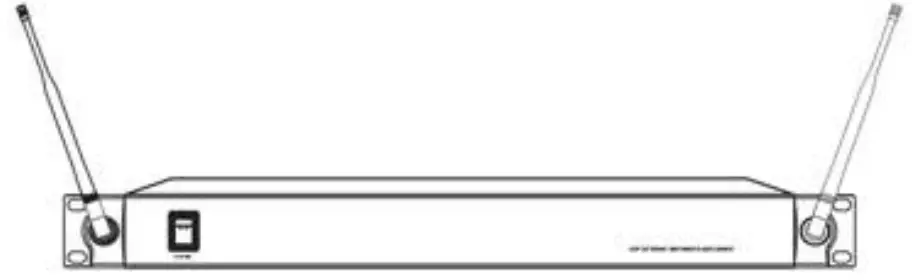
AT-4200 Receiver Rear Panel Features
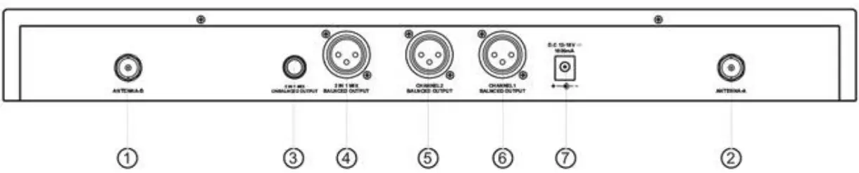
- Antenna Jack B 50 ohm
- Antenna Jack A 50 OHM
- 1/4″ Mix Output Socket
- XLR Mix Output Socket
- XLR output Socket Channel 2
- XLR Output Socket Channel 1
- DC Power Adapter Socket
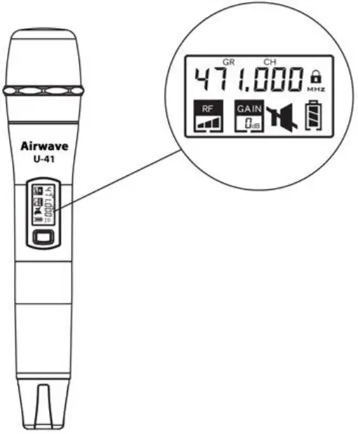
U-41 Handheld Transmitter Features
Functions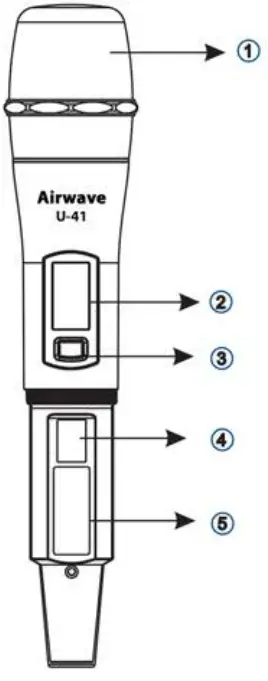
- Microphone Head
- LED Liquid Crystal Display
- Power & Mute Switch
- Infrared Frequency (IR) Port
- Battery Cover
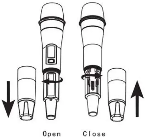
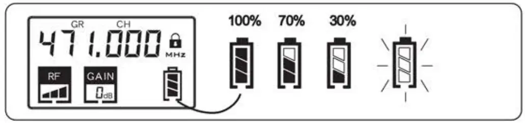
Changing Batteries:
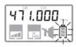
Two Alkaline batteries should provide power for approximately 10 hours. When the power indicator on the display is flashing, batteries should be replaced immediately as shown below.
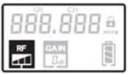
| Icon | Function |
 | Transmitter Intensity Indicator |
| Battery Power Indicator | |
 | Frequency Setting |
| Mute Icon | |
 | Microphone Gain Value |
Mute: Tap the power button to mute handheld transmitter, the icon will be displayed. Tap the power button again to clear mute.
- Microphone Gain Adjustment Display


- Transmitting Power Level Display
- Frequency Setting Display

- Low Power Tip: If the battery icon shows less than 309a, replace batteries immediately. Battery icon will Flas h pripr to shutting off.


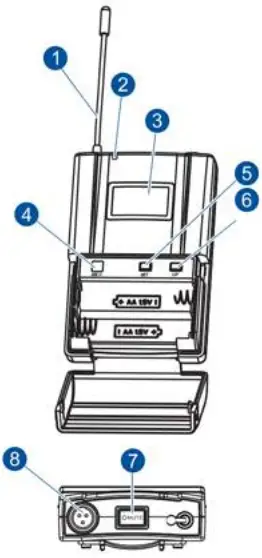
U-42Bodypack Transmitter Features
- Antenna
- Power Indicator Light
- LED Screen
- Infrared Frequency (IR) Window
- SET Button
- UP Button
- Power / Mute Button
- 3-Pin Microphone Input

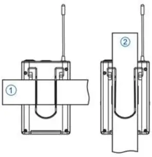
Wearing the Bodypack Transmitter
- Transmitter Clamped to a Belt
- Transmitter Clamped to Guitar Strap

Changing Batteries
Two Alkaline batteries should provide power for approximately J 0 hours. When the power indicator on the display is flashing, batteries should be replaced immediately as shown below.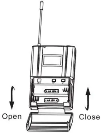
Frequency Selection Guide
Radio frequencies used for wireless communication in most countries including the United States are under strict control and regulations. These regulations specify which devises can be used at what frequency and tend to limit interference within the frequency bands.
To ensure consistent reliable frequency availability and to minimize the interference that might occur the user can choose frequency bands between 470 and 489 MHZ or 514 and 542 MHZ.
For the users convenience, and to help prevent interference, a number of preset frequency groups and channels have been programed into the system. For the use of a single system these preset frequencies usually do not need to be changed. When using multiple receivers and transmitters each system must use a separate and different channel. Grouping the receivers and then using separate channels on the transmitters will provide the best frequency use and distribution.
When using up to 4 units (max of8 channels) in the same frequency range, the wireless microphone system does not require an antenna combiner under normal conditions.
If using S to 7 units (10 to 14 channels) the use of an approved antenna combiner is highly recommended. The official antenna distribution partner of Airwave Technologies is RF Venue. They are without question, the leaders of antenna distribution.
Receiver Set Up
To Set Frequency and Channel:
Press ![]() button for 2 seconds to unlock
button for 2 seconds to unlock ![]() then press
then press ![]() button until “GR”(group) flashes. Press
button until “GR”(group) flashes. Press ![]() or
or ![]() to select the group. Figure. 1
to select the group. Figure. 1
Press ![]() until “CH”(Channel) is flashing. Press
until “CH”(Channel) is flashing. Press ![]() or
or ![]() to select channel. Figure 2
to select channel. Figure 2
Press ![]() until “SQL“(squelch) flashes. Press
until “SQL“(squelch) flashes. Press ![]() or
or ![]() to select a squelch start with three stall regulation. Figure 3
to select a squelch start with three stall regulation. Figure 3
Press ![]() until “TX SET” and ”RF” are flashing. Press
until “TX SET” and ”RF” are flashing. Press ![]() or
or ![]() to adjust the transmitter power level as necessary. Figure 4
to adjust the transmitter power level as necessary. Figure 4
Press until “TX SET and “GAIN” are flashing. Press ![]() or
or ![]() to adjust microphone gain as necessary. Figure 5
to adjust microphone gain as necessary. Figure 5
To Set Receiver Volume Control:
This unti has an electronic volume control system.
To adjust the system press the ![]() button for two seconds to unlock
button for two seconds to unlock ![]() then release. Press
then release. Press ![]() or
or ![]() button to control receiver output volume. Figure 8.
button to control receiver output volume. Figure 8.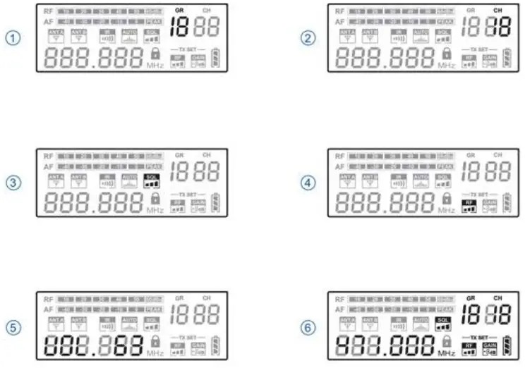
Setting Automatic Frequency
Handheld Transmitter: Turn off the power switch of the handheld transmitter, and then open the battery cylinder. Point its IR window to the IR window of the receiver. Press the ![]() button of the receiver and turn on the power switch of the handheld transmitter.
button of the receiver and turn on the power switch of the handheld transmitter.
Bodypack Transmitter: Point the IR window of the bodypack transmitter to the IR window of the receiver. Press the ![]() button of the receiver and the
button of the receiver and the ![]() button of the bodypack.
button of the bodypack.
Whenever the ![]() button of the receiver is pressed, synchronizing signal will be transmitted continuously for 25 sec and
button of the receiver is pressed, synchronizing signal will be transmitted continuously for 25 sec and ![]() on the screen flashes. When the infrared receiving circuit is enabled,
on the screen flashes. When the infrared receiving circuit is enabled, ![]() On the handheld transmitter will flash and the entire display screen of the bodypack transmitter will flash along with the infrared transmission indicator lamp.
On the handheld transmitter will flash and the entire display screen of the bodypack transmitter will flash along with the infrared transmission indicator lamp.
When establishing infrared connection between the receiver and the transmitter, the distance between them should not exceed 2 feet. When more than one system is used, only IP window of one trdr?5mitt£’r Should be pointed to the receiver for each infrared Connection.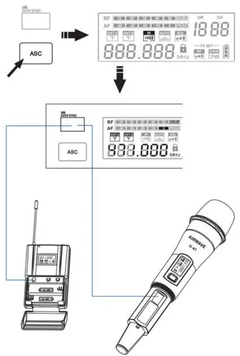
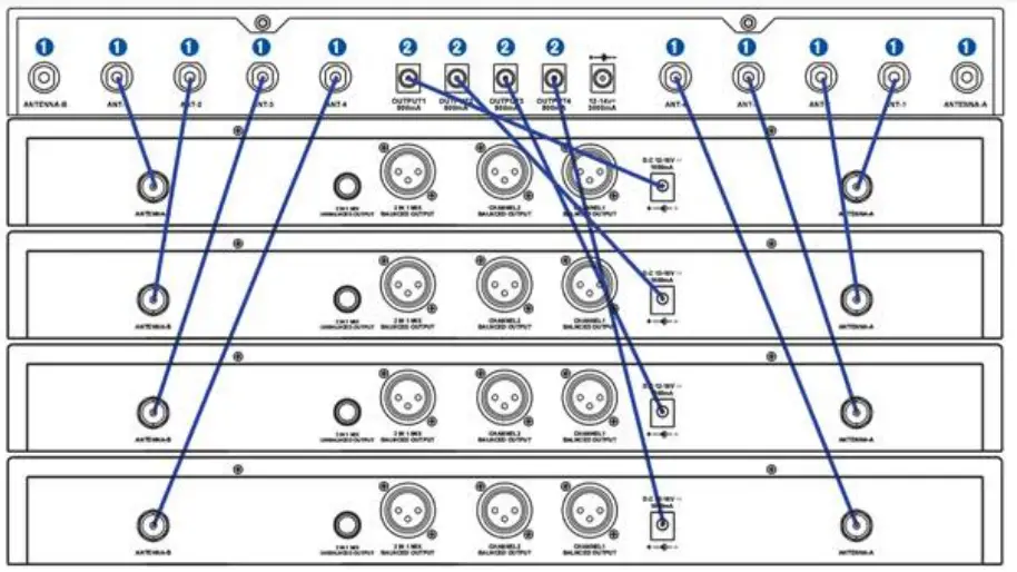
Audio Rack Connection Diagram
- TNT/BNC dual head connecting line {Optional Accessory

- Power connecting line

- Direct power adapter socket

- Airwave Rack Mount System

- Antenna Combined & Amplifier


Important Safety Instructions
- Transmitter and antenna should remain in line of sight for best signal reception.
- Do not place the receiver in close proximity to a metal surface or near any digital device.
- Receiver should be placed 3‘ off the ground and have space surrounding to ventilate.
- Ventilation holes should not be covered.
- Two-way radios can interfere with any audio transmission. Insure the transmitter and receiver are far from these devices to eliminate potential sources of interference.
- Receiver should not be placed in direct sunlight and should be kept away from any water sources or open flame.
- Nominal operating temperature is -5° C – +50° C (23° F – 122° F)
Troubleshooting Guide
| Problem | Indicator ( la m p) state | solution |
| No sou nd or fa1nt sound | Transmitter Power Light Off | Confirm main power is on Confirm batteries are inserted correctly +/- Confirm batteries in transmitter are charged |
| receiver Power Indicator Off | Confirm AC power is connected to receiver via power jack. Confirm AC power supply is normal Confirm Voltage on power supply is normal | |
| Receiver RF Indicator illuminated | Adjust high receiver volume control Adjust high transmitter gain switch setting Chet receiver / amplifier / mixer connections | |
| receiver Power Indicator Off Receiver ft. indicator illuminated | Ensure receiver is away from metal surfaces. Ensure space between transmitter and receiver is free of obstacles. Verify transmitter and receiver are using the same frequency. | |
| Low-voltage light on transmitter | Replace Batteries in Transmitter | |
| Distortion or excess noise | RF Signal illuminated on receiver | Ensure that no potential sources of interference are nearby. (CD players, computers, digital devices, ear monitoring systems). Set receiver and receiver to a different frequency. fettucce the transmitter. signal Replace batteries. If using multiple systems – increase frequency interval between the systems. |
| Distortion level gradually increased | Low Battery Indicator flashing | Replace Batteries in Transmitter |
| Output has feedback and / or distortion. | Adjust the transmitter and receiver volume to appropriate levels. |
AT-4200 DUAL CHANNEL WIRELESS RECEIVER SPECIFICATIONS
- Frequency Range: 470-489MHz / 514-542 MHZ
- Modulation : FM
- Working Range: 328′
- Optional Frequency: 192
- Frequency Response: 50Hz 15KHz (+3dB)
- Dynamic Range: > 105dB
- THD: < 0.5%
- S/N Ratio: > 102dB(A)
- RF Sensitivity: < -95dBm
- Image Rejection: > 60dB
- Output Connectors: XLR•1/ 1/4-inch connectors 1
- Audio Output Level: XLR: +10dBV / 1/4-inch connector: +8dBV
- Impedance: XLR: 3K0 / 1/4-inch connector: 3K0
- Pilot Tone: 32.768KHz
- Display: LCD
- Power Requirements: 12V/0.5A DC
- Operating Temperature Range: 32°F – 122°F
- Dimensions: 6.299” (W) x 16.142” (L) x 1.732″ (H)
- Weight: 3.858 lb.
AT-U41 HANDH ELD MICROPHONE TRANSMITTER SPECIFICATIONS
- Capsule Frequency Response: 50Hz – 16KHz
- Capsule Sensitivity: -50dB 1 2dB V/PA@1KHz
- Capsule Directivity: Single Point
- Gain Adjustment Range: 0/3/6dB
- Input Impedance: SKS + 30% @ 1KHz
- Output Impedance: 400a + 30o / @ 1KHz
- Output Power: 2mW / 10mW / 30mW
- Spurious: >dB
- Pilot Tone: 32.768KHz
- Display: LCD
- Power Requirements: 1.5V x 2(AA)
- Battery Life: >10H/1300mAH
- Dimensions: 9.84″ x 1.97″
- Weight: 12.7oz
AT-U42 BODYPACK TRANSMITTER SPECIFICATIONS
- Gain Adjustment Range: 0/3/6dB
- Input Impedance: SKS
- Output Power: 2mW / 10mW / 30mW
- Harmonic Rejection: > 50dB
- Pilot Tone: 32.768KHz
- Display: LCD
- Power Requirements: 1.5V x 2(AA)
- Battery Life: >10H/1300mAH
- Dimensions: 6.5” x 2.56″ x .91″
- Weight: 4.59oz
FCC Statement
FCC ID: 2AINTAT-4200 – This equipment has been tested and found to comply with the limits for a class 8 digital device, pursuant to part \ S of the FCC Rules.
These limits are designed to provide reasonable protection against harmful interference in a residential installation.
This equipment generates, uses and can radiate radio frequency energy and if not installed and used in accordance with the instructions, may cause harmful interference to radio communications.
However, there is no guarantee that interference will not occur in a particular installation. If this equipment does cause harmful interference to radio or television reception,
which can be determined by turning the equipment off and on, the user is encouraged to try to correct the interference by one or more of the following measures
- Reorient or relocate the receiving antenna
- Increase the separation between the equipment and receiver
- Connect the equipment into an outlet on a different circuit
- Consult the dealer or an experienced radio/TV technician for help
This equipment has been verified to comply with the limits for a class B computing device, pursuant to FCC Rules. In order to maintain compliance with FCC regulations, shielded cables must be used with this equipment. Operation with non-approved equipment or unshielded cables is likely to result in interference to radio and TV reception. The user is cautioned that changes and modifications made to the equipment without the approval
of manufacturer could void the user’s authority to operate this equipment.
Warranty Information & Technical Support
At Airwave Technologies, we believe in and stand behind all of our quality products.
Any reasonable warranty claim will be honored within a one year period. If anything is defective, simply call 305-891-7399 for an RA#, write it on the out side of a shipping box, and send us the defective piece or system, and we will gladly repair or replace it for you.
Please contact an Airwave Technologies dealer near you for parts and accessories for your wireless system.
Service Phone Number – 305-891 -7399
Service email – ServicegAirwaveTechnoIogies.com
Airwave Technologies, Inc.
ATTN: Service Department / RA#
290a Simms Street, Suite F
Hollywood, FL 33020
www.AirwaveTechnoIogies.com