Barebone XH510G PC/Workstation User Guide

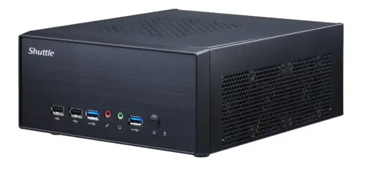
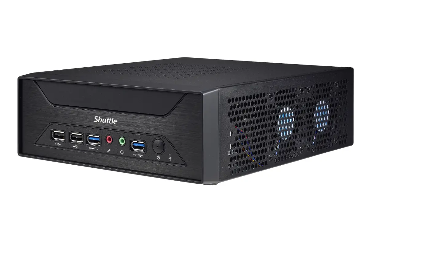
Product Overview
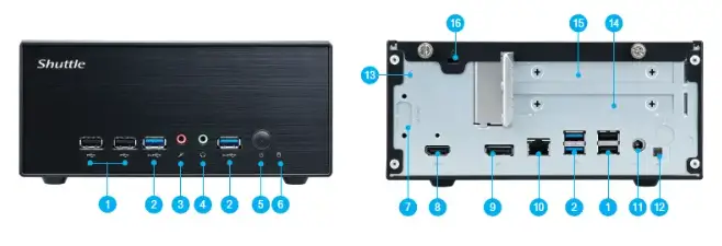
- USB 2.0 Ports
- USB 3.2 Gen1 Type-A Ports
- MIC-in
- Headphones
- Power switch / Power LED
- Hard disk drive LED
- COM port (optional)
- HDMI 2.0 Port
- DisplayPort
- LAN Port
- Power Jack (DC IN)
- Clear CMOS & Power Button & +5V
- Perforation for optional WLAN (optional)
- PCIe x16 slot
- PCIe x1 slot
- Kensington® Lock hole
Hardware Installation
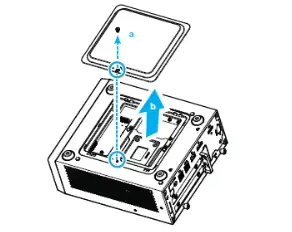
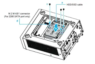
A. HDD/SSD and USB Installation
For safety reasons, please ensure that the power cord is disconnected before opening the case.
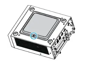
- Turn your XH510G2 upside down,then unscrew one screw of the HDD/SSD cover and remove it.

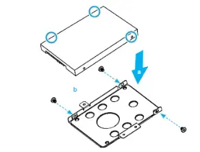
- Mount the HDD/SSD into the bracket with three screws.

- Tear off the adhesive tape of the HDD cable. Install the HDD or SSD in the chassis using its bracket. Affix with three screws and connect the HDD or SSD with an HDD/SSD cable. Install the M.2 SSD, if required (refer step D).

- Replace the HDD/SSD cover and refasten the screw.

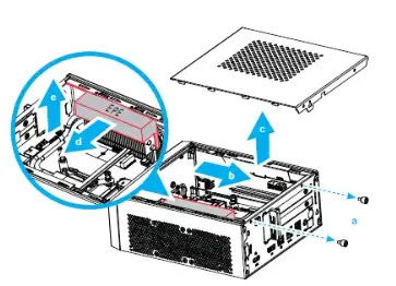
B. CPU and ICE Module Installation
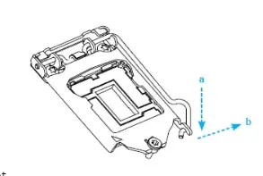
- Unscrew these two thumbscrews of the chassis cover, slide the cover backwards and upwards. Then remove the EPE protective foam from the top of the thermal fins.

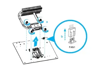
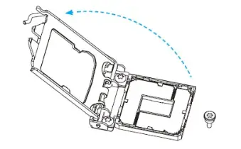
- Unfasten the four ICE module attachment screws and unplug the fan connector. Remove the ICE module from the chassis and put it aside.

Follow the steps below to correctly install the CPU into the motherboard CPU socket.
This CPU socket is fragile and can easily be damaged. Always use extreme care when installing a CPU and limit the number of times you remove or change the CPU. Before installing the CPU, make sure to turn off the computer and unplug the power cord from the power outlet to prevent damage of the CPU. - Unlock and raise the socket lever.

- Lift the metal load plate off the CPU socket.

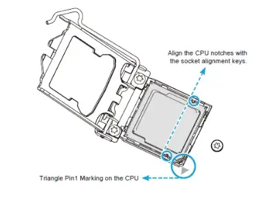
DO NOT touch the socket contacts. To protect the CPU socket, always use the protective socket covver when the CPU is not installed. - Please orientate the CPU correctly and align the CPU notches with the socket alignment keys. Make sure the CPU sits perfectly horizontal, then push it gently into the socket.

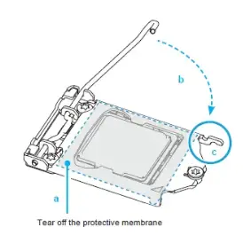
Please be aware of the CPU orientation, DO NOT force the CPU into the socket to avoid bending of pins on the socket and damage of CPU! - Tear off the protective membrane from the metal load plate.
Close the metal load plate, lower the CPU socket lever and lock in place.
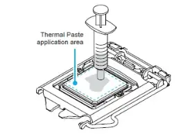
- Spread thermal paste evenly on the CPU surface.

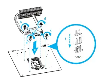
Please do not apply excess amount of thermal paste. - Screw the ICE module to the motherboard. Note to press down on the opposite diagonal corner while tightening each screw.
- Connect the fan.

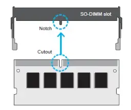
C. Memory Module Installation
This motherboard does only support 1.2 V DDR4 SO-DIMM memory modules.
- Locate the SO-DIMM slots on the motherboard.
- Align the notch of the memory module with the one of the relevant memory slot.

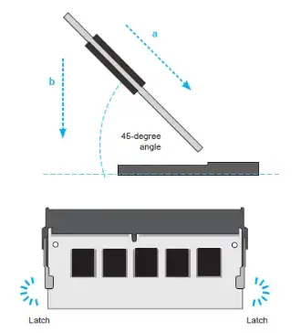
- Gently insert the module into the slot in a 45-degree angle.
- Carefully push down the memory module until it snaps into the locking mechanism.

- Repeat the above steps to install an additional memory module, if required.
D. M.2 Device Installation
- Locate the M.2 key slots on the motherboard.
M.2 2242/2260/2280 M key slot
M.2 2230 E Key slot
- Install the M.2 device into the M.2 slot and secure with the screw.
- M.2 2242/2260/2280 M key slot

- M.2 2230 E Key slot

- M.2 2242/2260/2280 M key slot
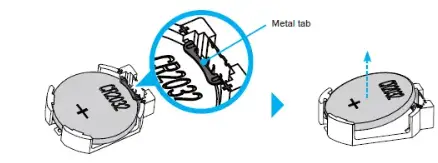
E. How to change the battery
- Use a flat-blade screwdriver to gently pry the metal tab to disengage the battery from the battery holder.

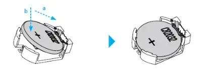
- Install the new battery, press it on the battery holder keeping the positive side facing top.

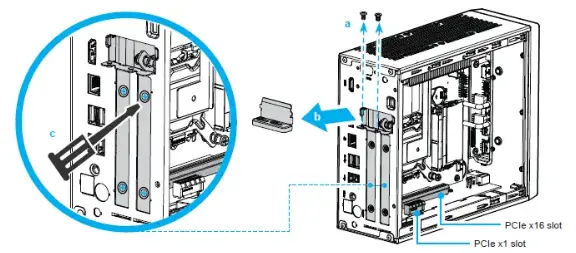
F. Installation of Expansion Card
- Unfasten the expansion slot bracket screw.
Remove the back panel bracket and put it aside.
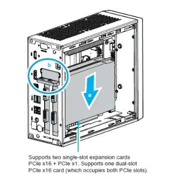
The maximum permitted size for display cards is 208.5 mm x 120 mm x 45 mm.
The display cards must be installed on the riser card, not on the motherboard.
- Install the PCIe x1 / PCIe x16 card into the PCIe x1 / PCIe x16 slots.

G. Complete
- Replace the cover and tighten the thumbscrews, then connect the power cord.
- Complete.
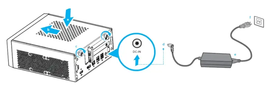
Please press the “Del” key while booting to enter BIOS. Here, please load the optimised BIOS settings.
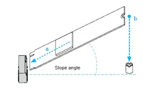
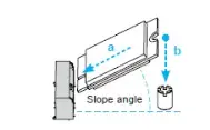
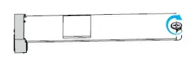
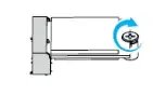
H. Installation of VESA Mount
- Follow the steps 1-2 to install the VESA mount.
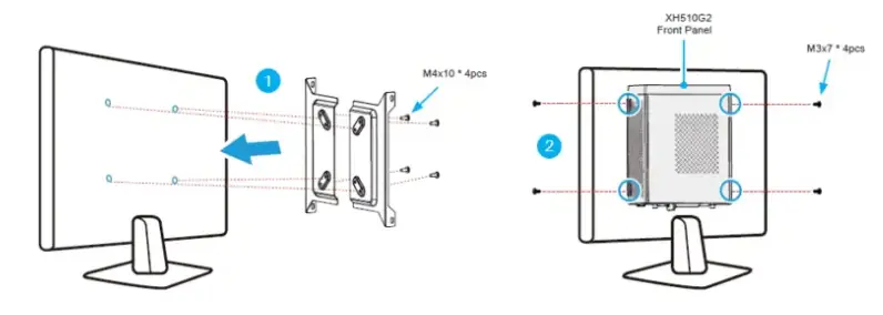
Supports 75×75 mm and 100×100 mm VESA standard.
Safety Information
Incorrectly replacing the battery may damage this computer.
Replace only with the same or equivalent as recommended by Shuttle.
Dispose of used batteries according to the manufacturer’s instructions.
This device complies with Part 15 of the FCC Rules. Operation is subject to the following two conditions: (1) this device may not cause harmful interference, and (2) this device must accept any interference received, including interference that may cause undesired operation.
Product Overview
- USB 2.0 ports
- USB 3.2 Gen1 Type-A Ports
- MIC-in
- Headphones
- Power switch / Power LED
- Hard disk drive LED
- COM port (optional)
- HDMI 2.0 Port
- DisplayPort
- LAN Port
- Power Jack (DC IN)
- Clear CMOS & Power button & +5V
- Perforation for optional WLAN (optional)
- PCIe x16 slot
- PCIe x1 slot
- Kensington® Lock hole
Motherboard Illustration
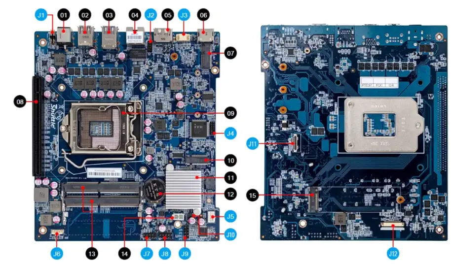
- Power Jack (DC IN)
- USB 2.0 Ports
- USB 3.2 Gen1 Type-A Ports
- LAN Port
- DisplayPort
- HDMI 2.0 Port
- M.2 2230 E key slot
- PCIe x16 slot
- Processor socket LGA1200
- M.2 2242/2260/2280 M key slot
- Intel® H510 Chipset
- CMOS battery holder
- DDR4 SO-DIMM slots
- 5V Power Supply connector
- M.2 2280 M key slot (SATA only)
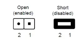
Jumper Settings
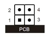
- Clear CMOS & power button & +5V

SW1 Pin Signal Name Pin Signal Name 1 RTCRST- 2 +5V 3 GND 4 PWRSW- - Port \ COM

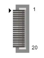
COM1 (RS232) Pin Signal Name Pin Signal Name 1 DCD 2 RX 3 TX 4 DTR 5 GND 6 DSR 7 RTS 8 CTS 9 RI 10 NULL - VGA Connector

CN4 Pin Signal Name Pin Signal Name 1 GND 11 CRT_HSYNC 2 GND 12 GND 3 VGA_SCL 13 GND 4 GND 14 GND 5 VGA_SDA 15 BOUT-O 6 GND 16 VGA_PWR 7 GND 17 GOUT-O 8 GND 18 VGA_PWR 9 CRT_VSYNC 19 ROUT-O 10 GND 20 VGA_PWR - Debug header

DBG1 Pin Signal Name Pin Signal Name 1 EC_ESCK 2 EC_EIO1 3 EC_PLRST_N 4 EC_EIO0 5 ESPI_CS0# 6 DEBUG_PWR 7 EC_EIO3 8 GND 9 EC_EIO2 10 NULL 11 ESPI_ALERT0# 12 ESPI_RST# - Fan connector

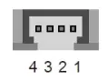
FAN1 Pin Signal Name 1 GND 2 +12V 3 SPEED_SENSE 4 PWM_CTRL - USB 2.0 cable connector \ USB 2.0

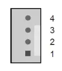
USB4 Pin Signal Name 1 GND 2 USB_D+ 3 USB_D- 4 USB_5V - Power header

SW1 Pin Signal Name Pin Signal Name 1 HDLEDPWR 2 SYSLEDPWR 3 SATA_LED 4 GND 5 RST_SW 6 PWR_SW 7 GND 8 GND 9 NC 10 NULL - USB connector \ USB

USB1 Pin Signal Name Pin Signal Name 1 USB_PWR 2 USB_PWR 3 USB3- 4 USB4- 5 USB3+ 6 USB4+ 7 GND 8 GND 9 NULL 10 GND - Front audio header

AUDIO1 Pin Signal Name Pin Signal Name 1 MIC_L 2 GND 3 MIC_R 4 AUDIO_JD 5 HP_R 6 MIC_JD 7 SENSE 8 NULL 9 HP_L 10 HP_JD - AC auto power-on

JP1 Pin Signal Name 1 AMP+ 2 GND - 2.5” SATA cable connector

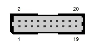
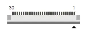
SATA1 Pin Signal Name Pin Signal Name 1 NC 11 +5V 2 NC 12 GND 3 NC 13 GND 4 NC 14 GND 5 GND 15 SATA_TX+ 6 GND 16 SATA_TX- 7 GND 17 GND 8 +5V 18 SATA_RX- 9 +5V 19 SATA_RX+ 10 +5V 20 GND - Front USB 3.0 header

USB5 Pin Signal Name Pin Signal Name Pin Signal Name 1 +3.3VS 11 U3_TX1P 21 U3_TX0N 2 +5VS 12 GND 22 GND 3 +5VS 13 USB2_N 23 U3_RX0P 4 +5VS 14 USB2_P 24 U3_RX0N 5 PWR_USB# 15 GND 25 GND 6 GND 16 GND 26 PWR_USB# 7 U3_RX1N 17 USB1_P 27 +5VS 8 U3_RX1P 18 USB1_N 28 +5VS 9 GND 19 GND 29 +5VS 10 U3_TX1N 20 U3_TX0P 30 +3.3VS