![]() Quick Installation Guide
Quick Installation Guide
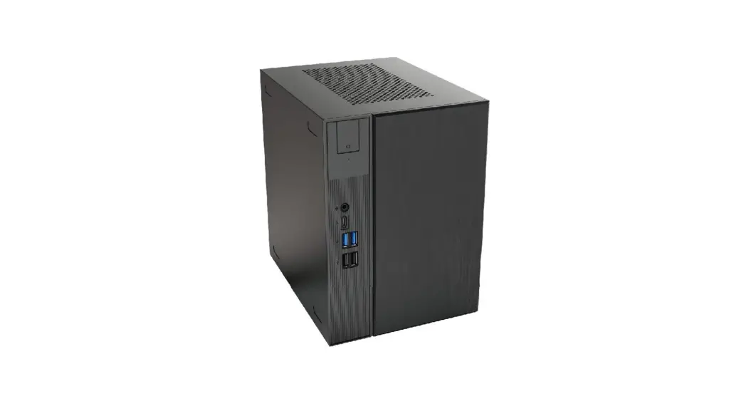
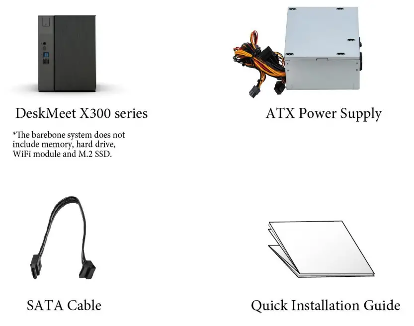
DeskMeet X300 Series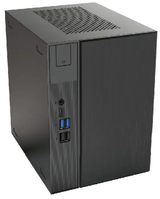
DeskMeet X300 Series Powerful and Compact Desktop PC
We recommend you wear gloves while building/un-building the DeskMeet to protect your hands and the PC hardware.
Be sure to follow the procedures in this guide and put the DeskMeet together in the correct order.
Package Contents
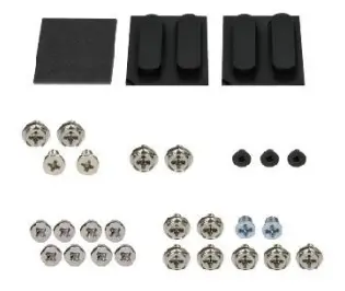
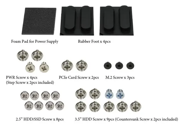
Screw Package
Rubber Foot x 4pcs, M.2 Screw x 3pcs, 2.5″ HDD/SSD Screw x 8pcs, 3.5″ HDD Screw x 9pcs (Countersunk Screw x 2pcs included), PWR Screw x 4pcs (Step Screw x 2pcs included), PCIe Card Screw x 2pcs, Foam Pad for Power Supply
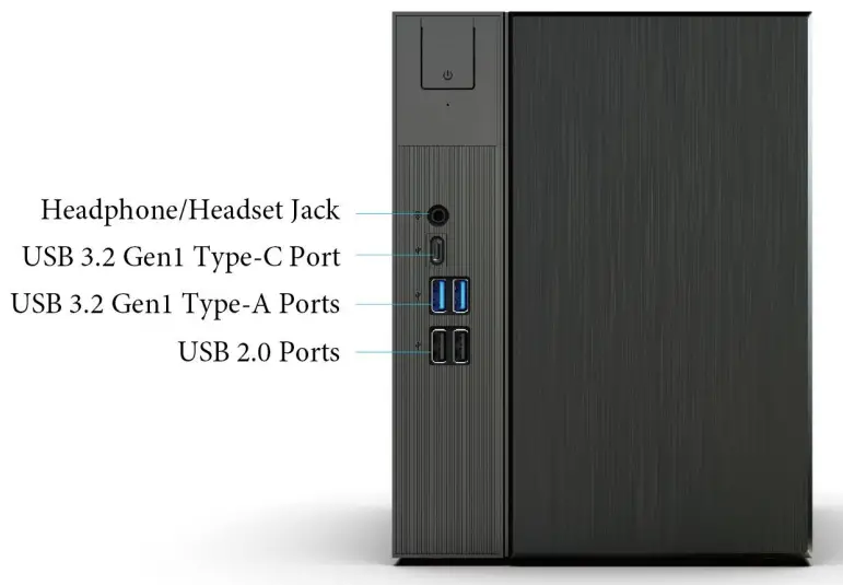
Front View
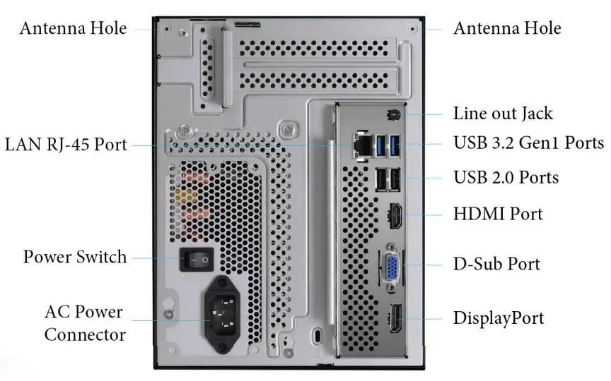
Rear View
Motherboard Layout
Top View
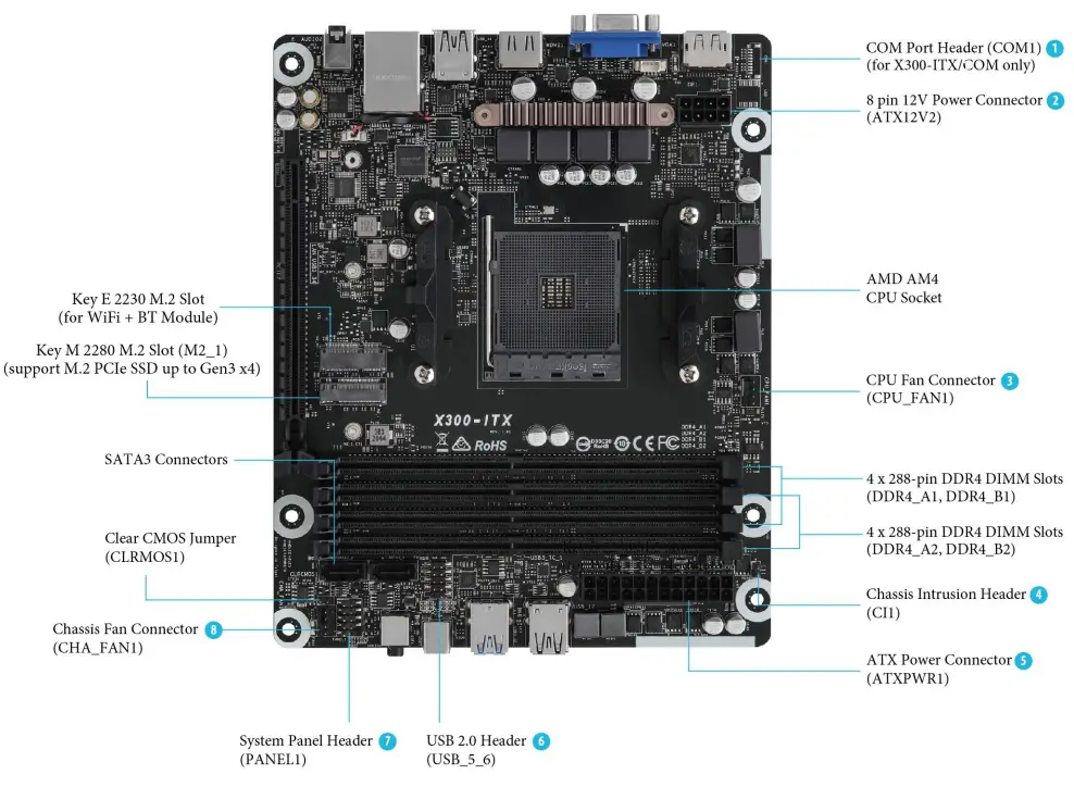
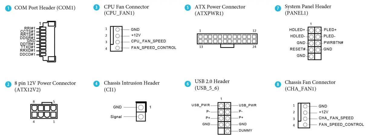
Onboard Connectors
Screw Package
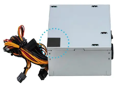 Attach the foam pad to this position of the power supply to avoid damaging the case.
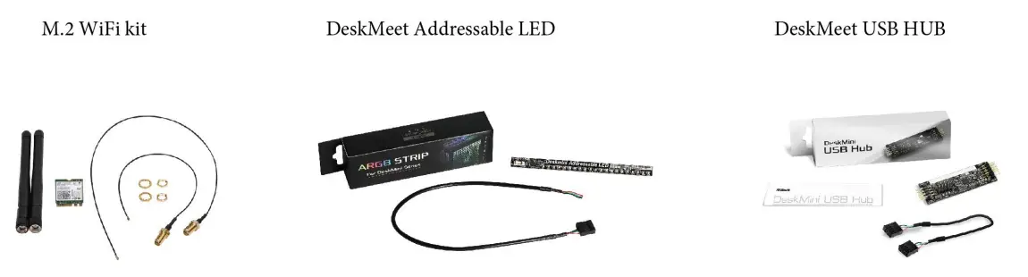
Customization Options
Hardware Installation
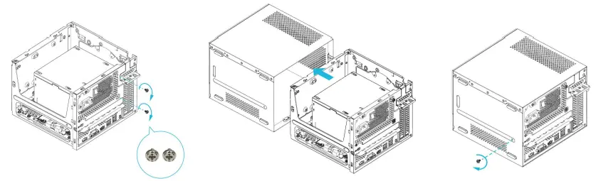
A Begin Installation
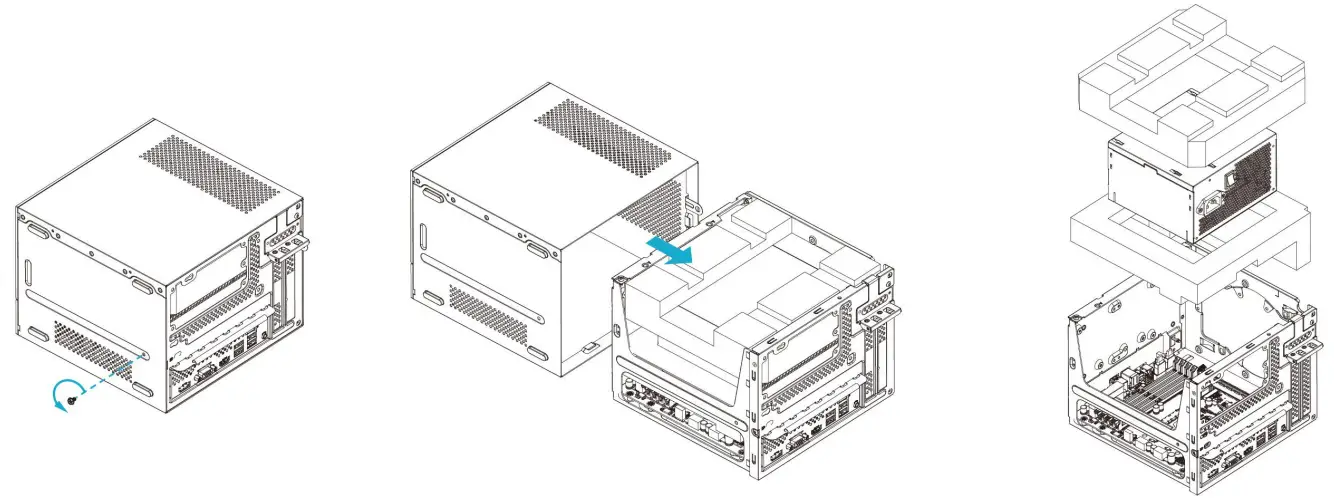 | ||
| 1. Remove the screw from the bottom side of the case. | 2. Pull out the motherboard tray. | 3. Remove the PSU and EPE Sponge. |
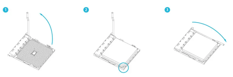
B Installing the CPU
C Installing the CPU Fan and Heatsink
Installing the CPU Box Cooler -1
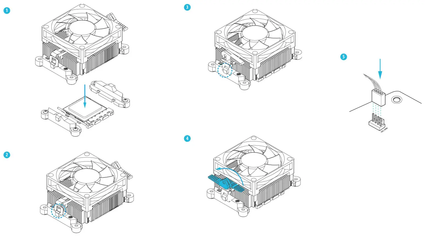 *For more details on the CPU Cooler installation, please refer to the user manual.
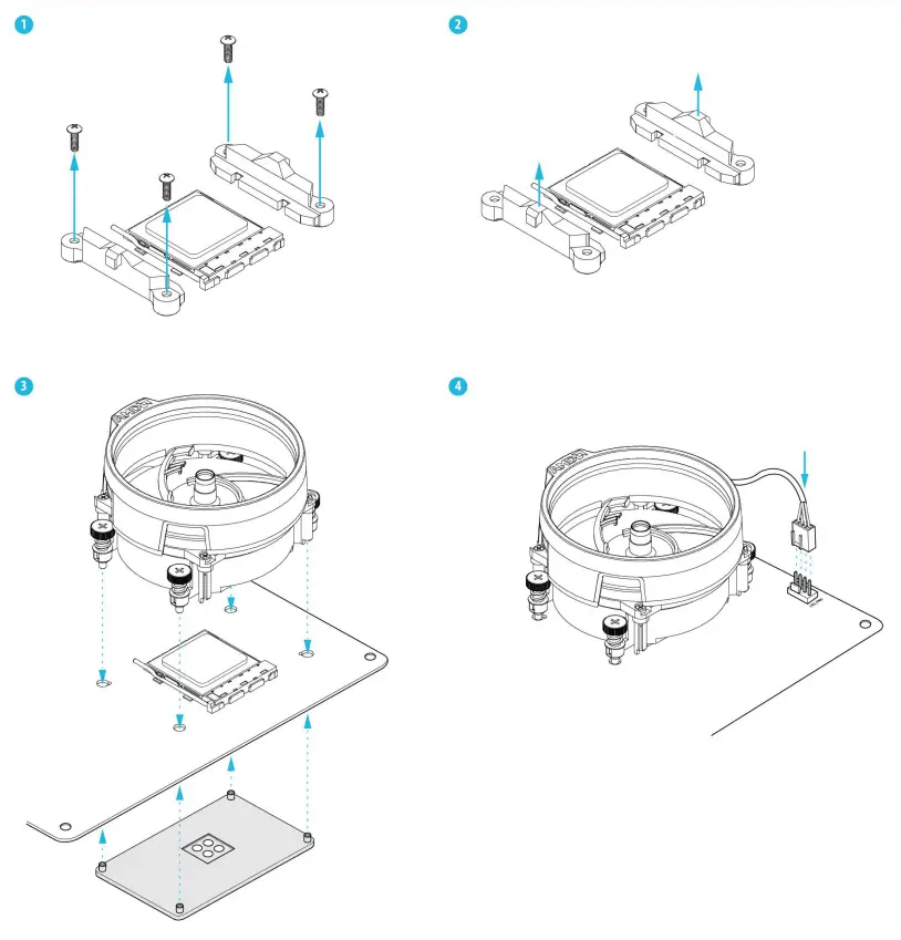
Installing the CPU Box Cooler -2
D Installing Memory Module
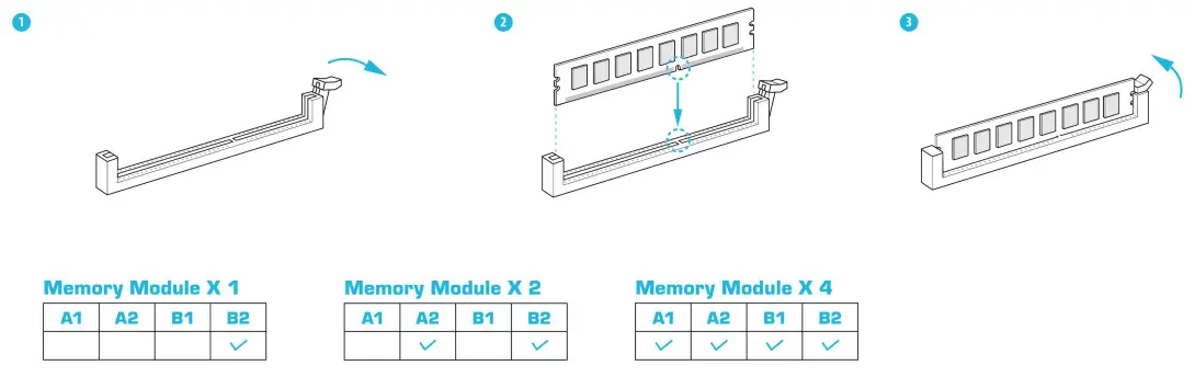
*The DeskMeet X300 series requires DDR4 DIMM.
*For dual channel configuration, you always need to install identical (the same brand, speed, size, and chip-type) DDR4 DIMM pairs.
E Installing the M.2 WiFi/BT Module and WiFi Antennas
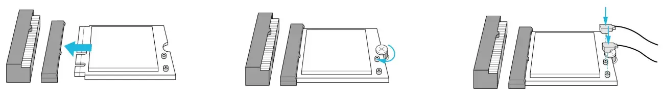 | ||
| 1. Insert the WiFi/BT module into the M.2 slot. | 2. Tighten the screw to secure the motherboard. | 3. Attach the SMA Wi-Fi Antenna Cables to the module. |
 | ||
| 4. Insert the SMA Wi-Fi Antenna Cables to the designated holes. Make sure that the cable routing is organized as shown in the illustration above. | 5. Insert the Wi-Fi Antenna Connectors to the antenna ports on the rear panel | 6. Fasten the screw nuts to secure the antenna connectors. |
F Installing the Type 2280 Ultra M.2 SSD
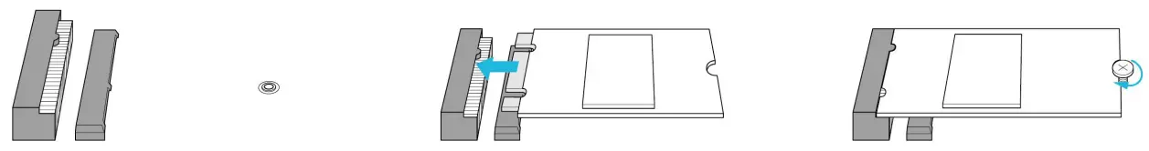 | ||
| 1. Locate the M.2 slot on the motherboard. | 2. Carefully insert the M.2 SSD into the slot. | 3. Tighten the screw to secure the M.2 SSD to the motherboard. |
G Installing the 3.5-inch HDD
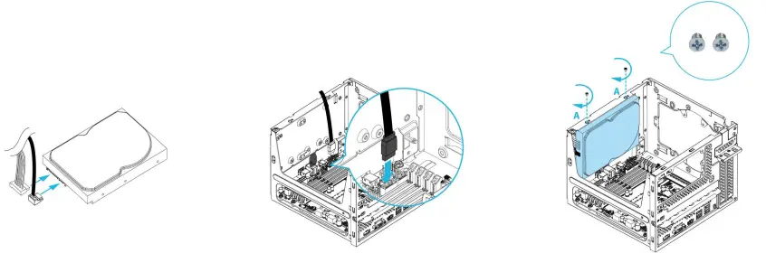 | ||
| 1. Connect the SATA Data and Power Cable to the HDD. | 2. Connect the SATA Data Cable to the SATA Connector on the motherboard. | 3. Locate the drive mounting location. Place an HDD and secure it with two screws. |
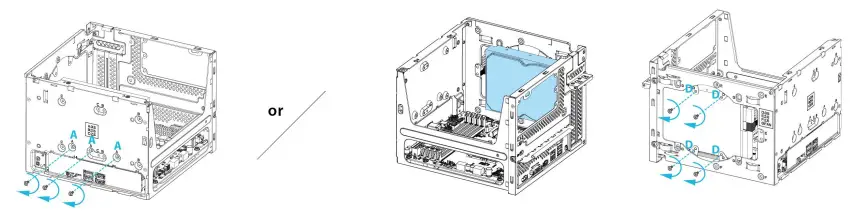 | ||
| 4. Secure the HDD with three more screws. | Place an HDD as shown in the picture If you install a 3.5-inch HDD in this. above. Then secure the HDD with four screws. location, you won’t be able to install a graphics card | |
H Installing the 2.5-inch HDD/SSD
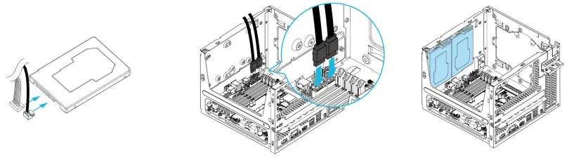 | ||
| 1. Connect the SATA Data and Power Cable to the HDD. | 2. Connect the SATA Data Cable to the SATA Connector on the motherboard. | 3. Locate the drive mounting location. Place two 2.5-inch HDDs/SSDs. |
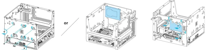 | ||
| 4. Secure the HDDs/SSDs with eight screws. | Place one 2.5-inch HDD/SSD as shown in the picture above. Then secure the HDD/SSD with three screws. * If you install a 2.5-inch HDD/SSD in this place, you won’t be able to install a dual-slot graphics card, but a single-slot graphics card can be installed. | |
I Installing the Fan / Liquid Cooler
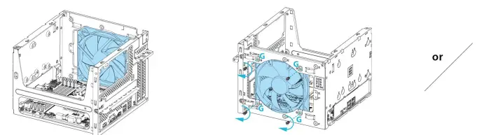 | |
| 1. Place the fan as shown in the picture above. | 2. Secure the fan with four screws. * if you install a fan in this location, you won’t be able to install a graphics card. |
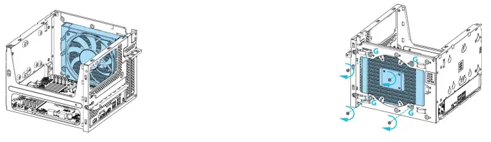 | |
| 1. Place the single radiator liquid cooler as shown in the picture above. * A total thickness of less than 45mm is required for the liquid cooler to be installed. | 2. Secure the liquid cooler with four screws. * If you install a fan in this location, you won’t be able to install a graphics card. |
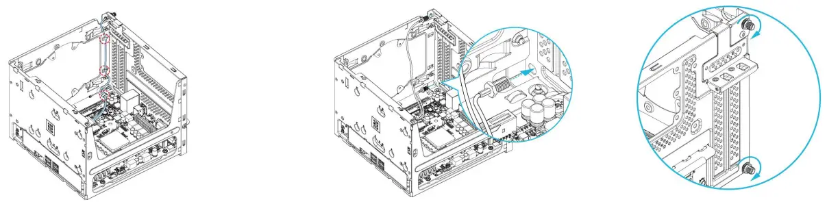
J Installing the Graphics Card
 | |
| 1. Open the latch. | 2. Insert the graphics card into the PCIe slot on the motherboard. Then close the latch and secure it with two screws. |
K Complete
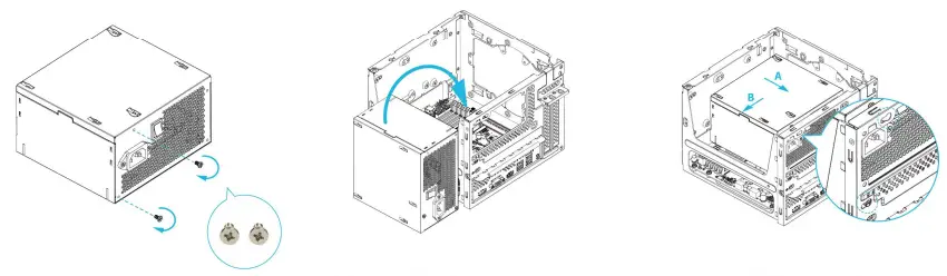 | ||
| 1. Fasten the two-step screws. | 2. Put the PSU back into the case. | 3. Move the PSU in the direction shown above. |
 | ||
| 4. Secure the PSU with two screws. | 5. Slide the motherboard tray back to the chassis. | 6. Secure the screw at the bottom side of the case. |
How to Remove the Motherboard from the Case
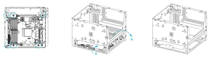 | ||
| 1. Remove the six screws securing the motherboard to the case. | 2. Open the I/O cover. Then remove the motherboard from the case. | 3. Complete. |
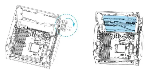
How to Install the Motherboard
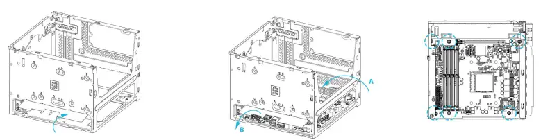 | ||
| 1. Open the I/O cover. | 2. Place the motherboard into the case. Then close the I/O cover. | 3. Fasten the six screws to secure the motherboard. |
Support
Please visit our website at http://www.asrock.com for: A list of tested memory, M.2, 2.5″ SATA HDD, wireless interface cards, and operating systems that are supported; for information about downloading the latest driver and BIOS updates; as well as the latest product support information.
The terms HDMI and HDMI High-Definition Multimedia Interface, and the HDMI logo are trademarks or registered trademarks of HDMI Licensing LLC in the United States and other countries.![]()
| Equipment name: PC Type designation (Type): DeskMeet series | ||||||
| Unit | Restricted substances and their chemical symbols | |||||
| Lead (Pb) | Merew y (Hg) | Cadmium (Cd) | Hexavalent chromium (Cr +6) | Polybrominated biphenyls (PBB) | Polybrominated diphenyl ethers (PBDE) | |
| Plastic Case | 0 | 0 | 0 | 0 | 0 | 0 |
| PCB | 0 | 0 | 0 | 0 | 0 | 0 |
| Power Supply | 0 | 0 | 0 | 0 | 0 | 0 |
| CPU Fan | 0 | 0 | 0 | 0 | 0 | 0 |
| Note 1: “Exceeding 0.1 wt %” at d “exceeding 0.01 wt %” indicates that the percentage content of the restric S substance exceeds the reference pe tentage value of the present condition. Note 2: “o” indicates that the percentage content of the restricted substance does not exceed the percentage of the reference value of presence. Note 3: The “—” indicates that the restricted substance corresponds to the exemption. | ||||||
Warranty Term
– Warranty of host of DeskMeet series personal computer (casing excluded): 1 year
– Warranty of transformer: 1 year
– Our warranty does not cover the casing of the product, fastenings, screws, or packaging accessories.
– Data stored in the product may be lost as a result of the repair work or re-formatting of the hard drive disk. ASRock does not provide data recovery services or data storage. Please back up your data regularly to protect the data and avoid loss. For details of our warranty terms, please refer to the individual warranty statement applicable to the district where your product was bought.
Safety & Regulatory Information
Failure to use the included Power Supply may violate regulatory compliance and may expose the user to safety hazards.