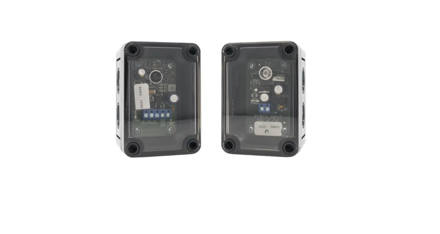
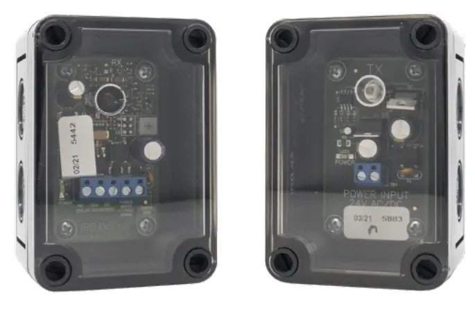
EMX IRB-4X Thru Beam Infrared Photoeye Safety Sensor
Instruction Manual
The IRB-4X thru beam photoeye is an external entrapment protection device type B1, non-contact sensor for use with automatic gates and doors. The photoeye provides a signal to the gate or door operator that the beam is or is not obstructed. The IRB-4X operates up to 115 feet in a weather-proof NEMA 4X housing. A red alignment indicator on the receiver provides status information at a glance, making set-up and alignment easy.
Cautions and Warnings
This product is an accessory or part of a system. Install the IRB-4X according to instructions from the gate or door operator manufacturer. Comply with all applicable codes and safety regulations.
The IRB-4X is not UL compliant. This photoeye will not work with gate or door operators that require monitored safety devices.
Specifications
| Operating Range | Up to 115 ft. (35 m) |
| Power | 12-24 VDC/AC |
| Current Draw of Transmitter | 37 mA |
| Current Draw of Receiver | 23 mA standby, 17 mA detect |
| Surge Protection | Thermal fuse |
| Relay Output Configuration | Form C contacts (NO, COM, NC) |
| Relay Contact Rating | 1 A at 24 VDC / 120 VAC |
| Operating Temperature | -40° to 170°F (-40° to 77°C) |
| Dimensions (L x W x H) | 2.3” (57 mm) x 2.6” (65 mm) x 3.7” (94 mm) |
| Environmental Rating | NEMA 4X |
Ordering Information
IRB-4X KIT
- Thru beam photo eye kit, includes a transmitter, receiver, protective hoods, and sun shield.
IRB-HD-SET
- Gold anodized aluminum protective hoods.
IRB-SH-SET
- Gray powder-coated steel protective hoods.
EMX Industries, Inc. IRB-4X_Rev2.1_062320
- Tech support: 216-518-9889
- [email protected]
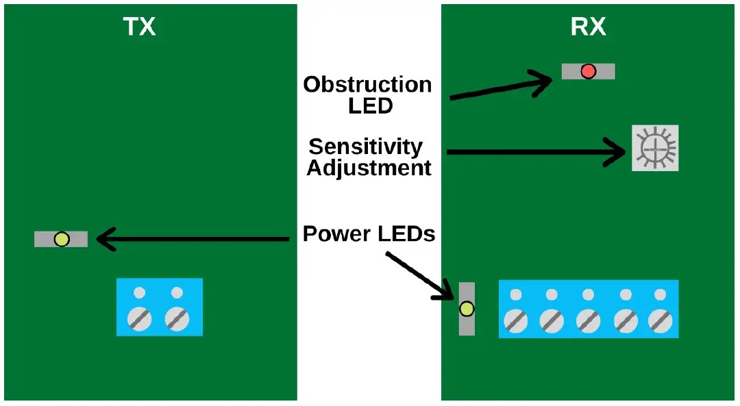
Board Diagram 
Installation
- Knock out the perforated hole on the transmitter and receiver housing that will be used to wire through. Be careful not to damage the electronic circuit board when knocking out the hole.
- Connect 12-24 VDC/AC power to the “Power Input” terminals on the transmitter (marked “TX”) and receiver (marked “RX”). The power input terminals are not polarity sensitive.
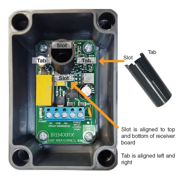
- Install the optional sunshield on the receiver as shown to the right in case of solar interference or cross talk.
- Connect the Common (COM) to the control input terminal per the operator manufacturer.
- Connect either the Normally Open (NO) or Normally Closed (NC) as needed to the control input terminal per the operator manufacturer.
- Adjust the sensitivity potentiometer as needed by turning counterclockwise to increase gain.
- Use the minimum sensitivity setting needed to achieve reliable detection.

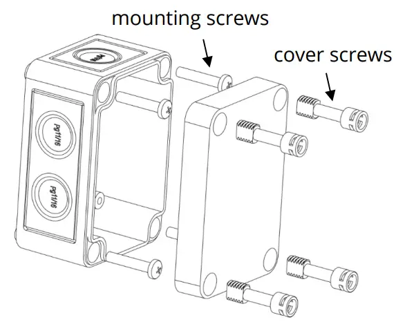
- Make sure the covers are attached and closed tight using all four plastic screws provided. The wiring to the enclosure must enter via UL listed watertight fitting such as a strain relief or watertight conduit connector.
- Verify that the IRB-4X transmitter and receiver are aligned and apply power.

| LED Indicators | |
| Green transmitter LED on | Power |
| Green receiver LED on | Power |
| Red receiver LED on | Beam blocked or not aligned |
- Place an obstruction (ex. hand) between the IRB-4X transmitter and receiver. The red LED on the receiver will turn on. Check the operator control board and verify that the safety input is recognized by the operator. Test the beam with an obstruction between the transmitter and receiver at multiple distances to confirm proper operation.
- Remove the obstruction and red LED will turn off.
TIP
- If IRB-4X is aligned but not detecting an obstruction, consider slowly reducing the sensitivity (clockwise) on the receiver until the obstruction is detected. This may be applicable for installations with a detection zone of less than 20 ft.
- On some variable frequency drives and noisy installations, it may be necessary to connect the bottom right mounting hole labeled “Earth Ground” to a wire connected to earth ground. Do not connect unless necessary.
Troubleshooting
| Symptom | Possible Cause | Solution |
| Does not detect obstruction | Sensitivity is too high
Signal is reflecting off another surface | Decrease sensitivity potentiometer clockwise.
Check area for highly reflective surfaces. |
| Receiver red LED on continuously, indicating an obstruction when one is not present | Sensitivity is too low | Increase sensitivity potentiometer counter-clockwise. |
| The transmitter does not have power | Check the power source of the transmitter. | |
| The receiver does not “see” the transmitter | Make sure the transmitter and receiver are aligned. | |
| Receiver activates but does not transmit a signal to the operator | The faulty connection between receiver and operator control input | Verify all wires and terminal connections. |
| Output relay chatters constantly between open and close | Interference | See step 10 under Installation and check if any reflective surfaces could be sending a signal into the receiver sensor. |
Warranty
- EMX Industries, Inc. products have a warranty against defects in materials and workmanship for a period of two years from date of sale to our customer.


