![]() Xi 80/400/410 CM Infrared Camera
Xi 80/400/410 CM Infrared Camera
Instruction Manual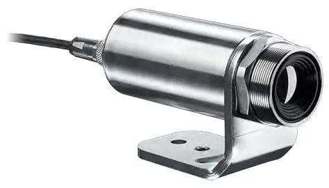
General Notes
1.1 Intended use
Thank you for choosing the optris® Xi spot finder infrared camera.
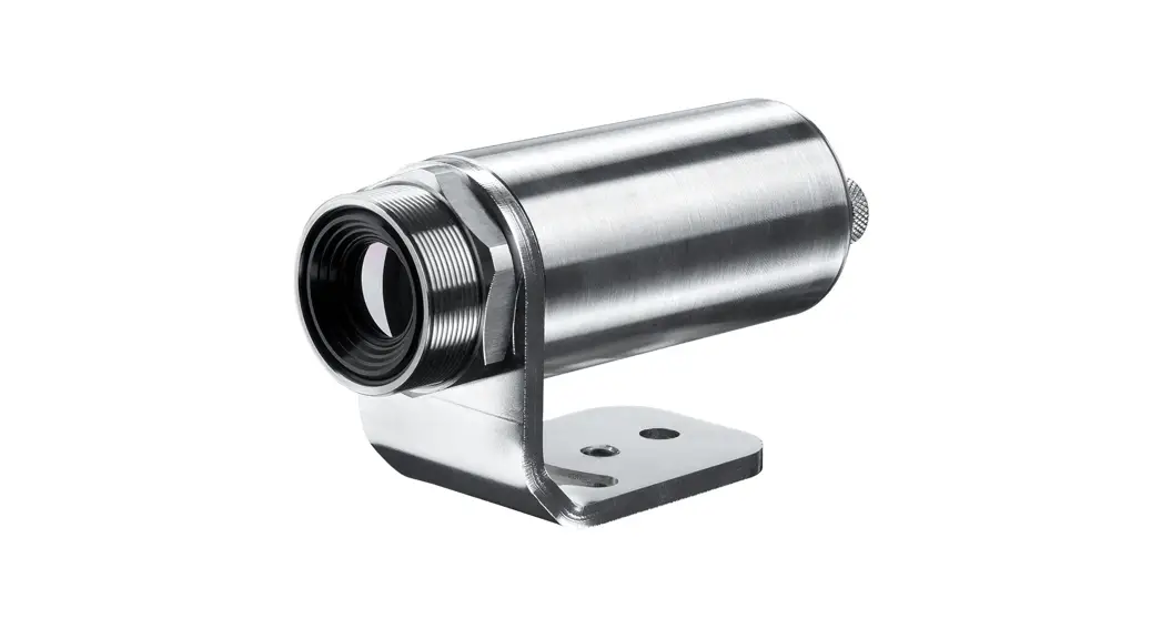
The optris Xi calculates the surface temperature based on the emitted infrared energy of objects [►8 Basics of Infrared Thermometry]. The two-dimensional detector (FPA – focal plane array) allows a measurement of an area and will be shown as thermal image using standardized palettes. The radiometric processing of the picture data enables the user to do a comfortable detailed analysis with the software PIX Connect.![]() The Xi is a precise instrument and contains an extremely sensitive infrared detector and a highquality lens.
The Xi is a precise instrument and contains an extremely sensitive infrared detector and a highquality lens.
The alignment of the camera to intensive energy sources (e.g. devices which emit laser radiation or reflections of such equipment) can cause an irreparable defect of the infrared detector. This is also valid if the camera is switched off.
Such kinds of damages are excluded from warranty.![]() Read the manual carefully before the initial start-up. The producer reserves the right to change the herein described specifications in case of technical advance of the product.
Read the manual carefully before the initial start-up. The producer reserves the right to change the herein described specifications in case of technical advance of the product.
 Avoid abrupt changes of the ambient temperature.
- Avoid static electricity, arc welders, and induction heaters. Keep away from very strong EMF (electromagnetic fields).
- In case of problems or questions which may arise when you use the infrared camera, please contact our service department. ► All accessories can be ordered according to the referred part numbers in brackets [ ].
1.2 Warranty
Each single product passes through a quality process. Nevertheless, if failures occur contact the customer service at once. The warranty period covers 24 months starting on the delivery date. After the warranty is expired the manufacturer guarantees additional 6 months warranty for all repaired or substituted product components. Warranty does not apply to damages, which result from misuse or neglect. The warranty also expires if you open the product. The manufacturer is not liable for consequential damage or in case of a nonintended use of the product.
If a failure occurs during the warranty period the product will be replaced, calibrated or repaired without further charges. The freight costs will be paid by the sender. The manufacturer reserves the right to exchange components of the product instead of repairing it. If the failure results from misuse or neglect the user has to pay for the repair. In that case you may ask for a cost estimate beforehand.
1.3 Scope of delivery
- Xi 80, Xi 400 or Xi 410
- USB cable: 1 m (standard scope of supply, no IP67 protection class) 1 m, 3 m, 5 m, 10 m, 20 m * (optional, for industrial applications, with IP67)
- Ethernet PoE cable: 1 m (only for Xi 410)
- Mounting nut and mounting bracket (adjustable in one axis, tripod thread)
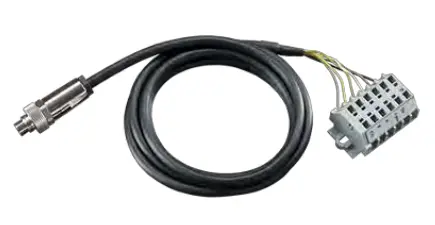
- Process interface cable incl. terminal block (1 m)
- Software package PIX Connect
- Quick start guide
* 10 m and 20 m version not available for Xi 80 and Xi 410
1.4 Maintenance![]() Never use cleaning compounds which contain solvents (neither for the lens nor for the housing).
Never use cleaning compounds which contain solvents (neither for the lens nor for the housing).
1.4.1 Cleaning
Blow off loose particles using clean compressed air. The lens surface can be cleaned with a soft, humid tissue (moistened with water) or a lens cleaner (e.g. Purosol or B+W Lens Cleaner).
1.5 Model overview
The cameras of the Xi-series are available in the following basic versions:
| Modell | Model code | Temperature range | Spectral range | Frame rate | Typical applications |
| Xi 80 | IR | -20 to 900 °C | 8 – 14 µm | USB/Ethernet: 50 Hz | Surface measurements in industrial application, autonomous operation with automatic spot finder |
| Xi 400 | IR | -20 to 900 °C 200 to 1500 °C (optional) | 8 – 14 µm | USB: 80 Hz/ 27 Hz | Real-time thermographic images in high speed; Detection of smallest temperature differences |
| Xi 410 | IR | -20 to 900 °C | 8 – 14 µm | Ethernet: 25 Hz USB: 4 Hz | Surface measurements in industrial application, autonomous operation with automatic spot finder |
Table 1: Model overview
Technical Data
2.1 General specifications
| Environmental rating: | IP67 (NEMA-4) |
| Ambient temperature: | 0…50 °C |
| Storage temperature: | -40…70 °C |
| Relative humidity: | 10…95 %, non-condensing |
| Material (housing): | Stainless steel |
| Dimensions: | Xi 80: 36 x 90 mm / M30 Xi 400/410: 36 x 100 mm / M30 |
| Weight (without mounting bracket): | Xi 80: 201-210 g (depending on optics) Xi 400/410: 216-220 g (depending on optics) |
| Cable length: | USB: 1 m (standard), 3 m, 5 m, 10 m, 20 m (20 m version not available for Xi 80/410) Ethernet / RS485 (Xi 80/410): 100 m |
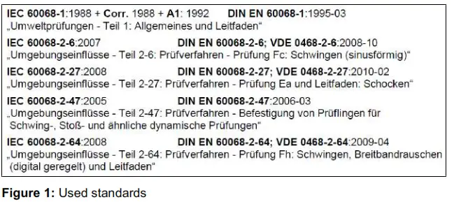
| Vibration 1): | IEC 60068-2-6 (sinus shaped) IEC 60068-2-64 (broadband noise) |
| Shock 1): | IEC 60068-2-27 (25 G and 50 G) |
1) Used standards for vibration and shock:
Stress program (camera in operation):
| Shock, half sinus 25 G – testing Ea 25 G (acc. IEC 60068-2-27) | ||
| Acceleration | 245 m/s2 | (25 G) |
| Pulse duration | 11 ms | |
| Number of directions | 6 | (3 axes with 2 directions each) |
| Duration | 600 Shocks | (100 Shocks each direction) |
| Shock, half sinus 50 G – testing Ea 50 G (acc. IEC 60068-2-27) | ||
| Acceleration | 490 m/s2 | (50 G) |
| Pulse duration | 11 ms | |
| Number of directions | 6 | (3 axes with two directions each) |
| Duration | 18 Shocks | (3 Shocks each direction) |
| Vibration, sinus shaped – testing Fc (acc. IEC60068-2-6) | ||
| Frequency range | 10 – 500 Hz | |
| Acceleration | 29.42 m/s2 | (3 G) |
| Frequency change | 1 Octave/ min | |
| Number of axes | 3 | |
| Duration | 1:30 h | (3 x 0.30 h) |
| Vibration, broadband noise – testing Fh (acc. IEC60068-2-64) | ||
| Frequency range | 10 – 2000 Hz | |
| Acceleration | 39.3 m/s2 | (4.01 GRMS)) | |
| Frequency spectrum | 10 – 106 Hz | 0.9610 (m/s2)2/Hz | (0.010 G2/Hz) |
| 106 – 150 Hz | +6 dB/ Octave | ||
| 150 – 500 Hz | 1.9230 (m/s2)2/Hz | (0.020 G2/Hz) | |
| 500 – 2000 Hz | -6 dB/ Octave | ||
| 2000 Hz | 0.1245 (m/s2)2/Hz | (0.00126 G2/Hz) | |
| Number of axes | 3 | ||
| Duration | 3 h | (3 x 1 h) |
2.2 Electrical specifications
| Power Supply: | Xi 80/410: USB/ PoE/ 5-30 VDC Xi 400: USB |
| Current draw: | Max 500 mA |
| AO: Output Standard/Internal Process Interface (PIF out) | 0 – 10 V (Xi 400), 0/4 – 20 mA (Xi 80/410) (Main measure area, measure area, internal temperature, flag status, recording status, line scan status, alarm, frame sync, fail-safe, external communication) [►Appendix F – Wiring diagrams PIF] |
| AI: Input Standard/Internal Process Interface (PIF in) | 0 – 10 V (Emissivity, ambient temperature, reference temperature, uncommitted value, flag control, triggered recording, triggered snapshots, triggered line-scanner, triggered event grabber, reset peak-/valley-hold, switch temperature range) [►Appendix F – Wiring diagrams PIF] |
| DI: Digital Input Standard Process Interface (Xi 400) | Flag control, triggered recording, triggered snapshots, triggered line-scanner, triggered event grabber, reset peak-/valley-hold, switch temperature range [►Appendix F – Wiring diagrams PIF] |
| Digital interface: | Xi 80/410: USB 2.0/ Ethernet/ RS485 Xi 400: USB 2.0/ optional USB to GigE (PoE) conversion |
2.3 Measurement specifications
| Xi 80 | Xi 400 | Xi 410 | |
| Temperature ranges | -20…100 °C; 0…250 °C; (20) 150…900 °C 1) | 20…100 °C; 0…250 °C; (20) 150…900 °C 1) Option: 200…1500 °C | 20…100 °C; 0…250 °C; (20) 150…900 °C 1) |
| Spectral range | 8 – 14 µm | ||
| Detector | UFPA, 80 x 80 pixel @ 50 Hz | UFPA, 382 x 288 pixel @ 80 Hz/ 27 Hz | UFPA, Ethernet: 384 x 240 Pixel @ 25 Hz USB: 384 x 240 Pixel @ 4 Hz |
| Lenses (FOV) | 12° x 12° (F=1,0); 30° x 30° (F=0,9); 55° x 55° (F=0,9); 80° x 80° (F=0,9) | 18° x 14° (F=1,1); 29° x 22° (F=0,9); 53° x 38° (F=0,9); 80° x 54° (F=0,9) | 18°x12° (F=1,1), 29°x18° (F=0,9), 53°x31° (F=0,9), 80°x44° (F=0,9) |
| Microscope lens (FOV) | – | 18° x 14° (F=1,1, minimum spot size: 81 µm @ 90 mm, working distance: 90-110 mm) | – |
| Optical resolution | 190:1 (12° optic) | 390:1 (18° optic) | |
| System accuracy 2) | ±2 °C or ±2 % | ||
| Thermal sensitivity (NETD): | 100 mK | 80 mK | |
| Warm-up time | 10 min |
| Emissivity | 0.100…1.100 |
| Software / App | PIX Connect / IRmobile |
1) Accuracy statement effective from 150 °C
2)At ambient temperature 235 °C; whichever is greater
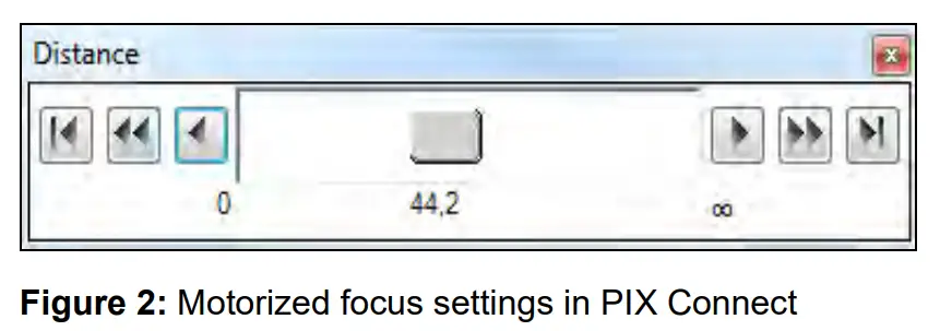
2.4 Optical specifications![]() Make sure that the focus of thermal channel is adjusted correctly. The cameras have a motorized focus, which can be adjusted in the PIX Connect software (Menu View/ Windows/Distance or over the icon
Make sure that the focus of thermal channel is adjusted correctly. The cameras have a motorized focus, which can be adjusted in the PIX Connect software (Menu View/ Windows/Distance or over the icon ![]() ). An adjustment to the left leads to the focus setting “near” and an adjustment to the right to the focus setting “infinite”.
). An adjustment to the left leads to the focus setting “near” and an adjustment to the right to the focus setting “infinite”.
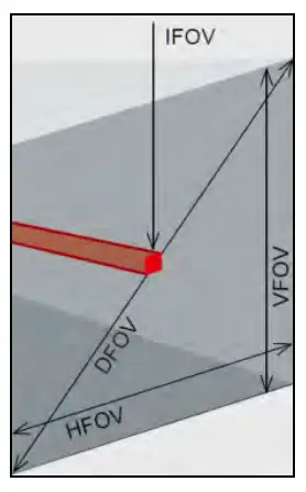
The variety of different lenses offers the possibility to precisely measure objects in different distances. We offer lenses for close, standard distances and large distances. Please note that the Xi has a fixed optic. A change of optics is not possible. Different parameters are important if using infrared cameras. They display the connection between the distance of the measured object and the size of the pixel (Table 2).
- HFOV: Horizontal enlargement of the total measuring at object level
- VFOV: Vertical enlargement of the total measuring at object level
- IFOV: Size at the single pixel at object level
- DFOV: Diagonal dimension of the total measuring field at object level
- MFOV: Recommended, smallest measured object size of 3 x 3 pixel (Xi 400/410) and 2 x 2 pixel (Xi 80)

Geometric resolution for ideal temperature measurement
When designing optics for measuring IR cameras, special attention must be paid to the quality of detail contrast with which an object can be represented in the image. This is described by the modulation transfer function (MTF). Since in contrast to visual cameras, with IR cameras the thermal contrast is of more interest, this is used together with the slit response function (SRF). The result is determined by the number of pixels an object needs to fill to allow its temperature to be measured exactly. In high-performance infrared optical systems as used by Optris, this is 3×3 pixels or 2×2 pixels, with lower quality optical systems, in some circumstances as many as 10×10 pixels may be required, to receive 90 % of the energy. A high-performance camera lens also allows a larger measuring distance with the same number of pixels of the detector, or the precise temperature measurement of smaller structures and objects. The 3×3 pixel (2×2 pixels) geometry is described as MFOV (measurement field of view) – one single pixel on the object surface is described as IFOV (instantaneous field of view). The MFOV is comparable with the measuring spot definition with infrared thermometers.
The following tables with examples showing what spot sizes and pixel sizes will be reached in which distance. For individual configuration there are different lenses available. Wide angle lenses have a radial distortion due to their large opening angle; the software PIX Connect has an algorithm which corrects this distortion. As an alternative to the tables below, the optics calculator can also be used on the optris or via the Optris calculator – Apps. The app can be downloaded for free from the Google Play Store (see QR code).

Table 2:
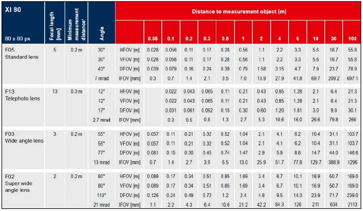
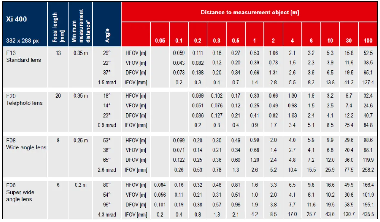
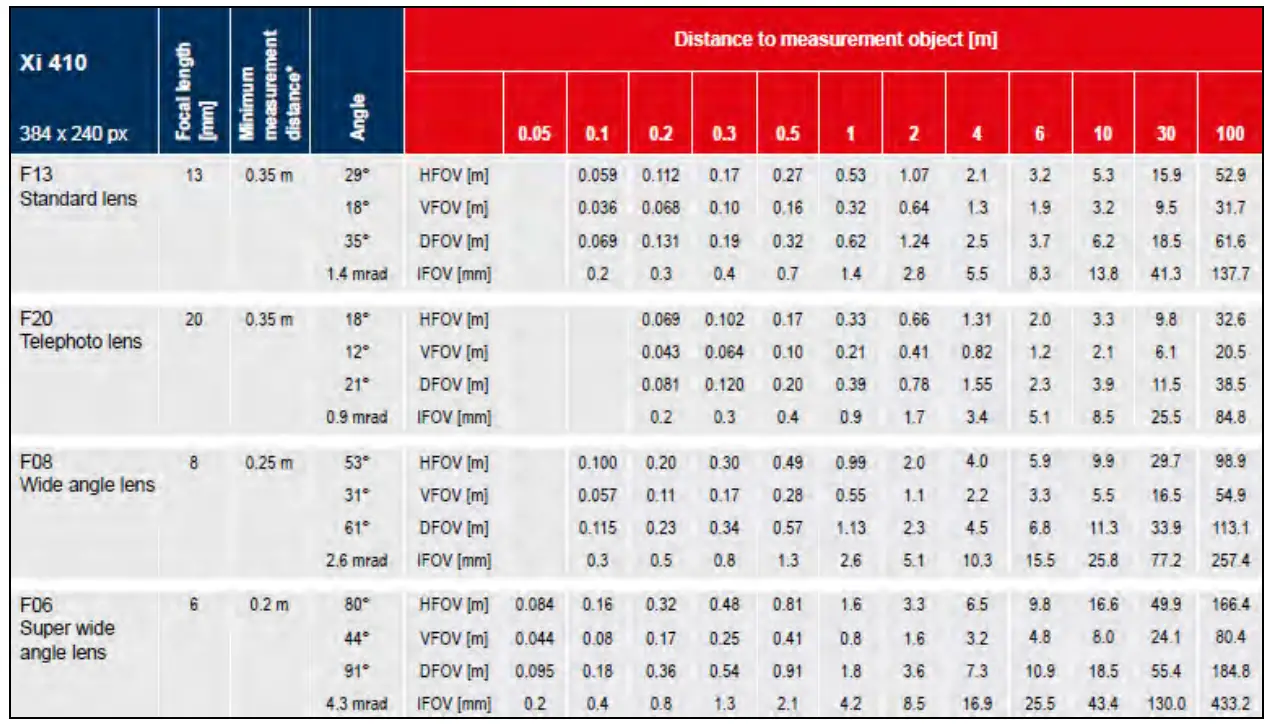
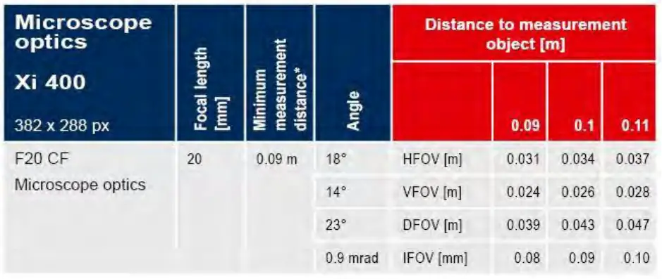
* Note: The accuracy of measurement can be outside of the specifications for distances below the defined minimum distance.
Mechanical Installation
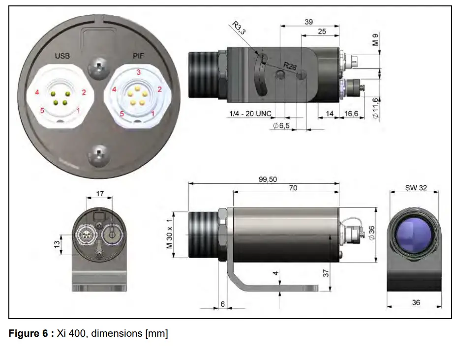
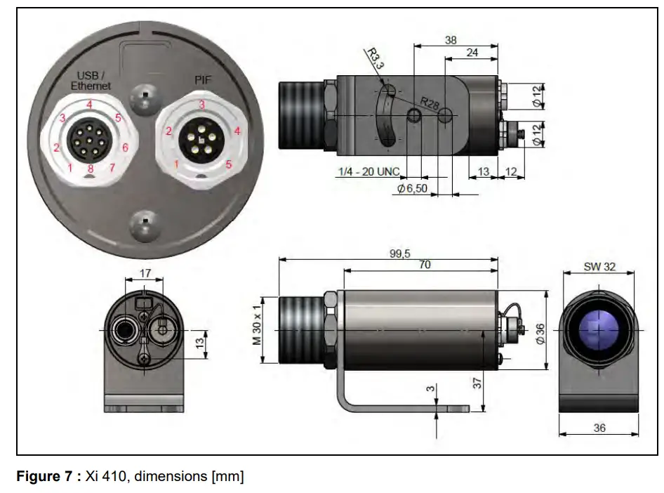
3.1 Dimensions
The Xi is equipped with a metric M30x1 thread and can be installed either directly via the sensor thread or with help of the supplied mounting nut (standard) and adjustable mounting bracket (standard) to a mounting device available.
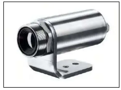 Figure 3: Xi with mounting bracket
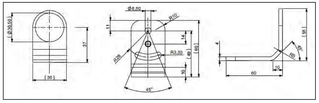 Figure 4: Mounting bracket, adjustable in one axis, with tripod thread
[Order No. – ACXIFB] – standard scope of supply
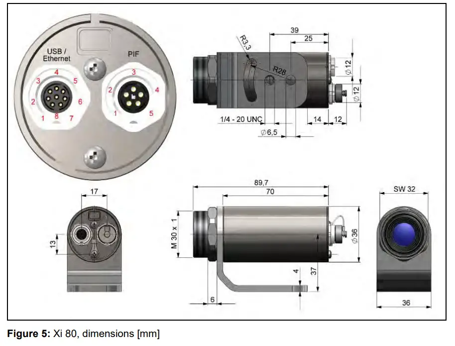
![]() For correct orientation, the USB port must be on the left side and the PIF port on the right side, see Figure 5 or Figure 6.
For correct orientation, the USB port must be on the left side and the PIF port on the right side, see Figure 5 or Figure 6.
 |  |
 |  |
3.2 Accessories
3.2.1 Air purge laminar
The lens must be kept clean at all times from dust, smoke, fumes and other contaminants in order to avoid reading errors. These effects can be reduced by using an air purge. (Part-No.: ACXIAPL)
- Make sure to use oil-free, technically clean air, only.
- The needed amount of air (approx. 2…10 l/min.) depends on the application and the installation conditions on-site.
- The laminar air purge has a Si-protective window. Typical transmission value: 0.82 (deviations possible), replacement window available under the Part-No.: ACXIAPLPWSI
- The corresponding mounting bracket (Part-No.: ACXIAPLAB) is mandatory.
- Material: Anodized aluminum, weight: 218 g / 494 g with mounting bracket
- Ambient temperature: 0…80 °C (TAmb camera: 0…50 °C); with water cooled housing up to 250 °C
Air flow
The air purge can be mounted infour different positions.
The direction of the airflow musalways be clear.
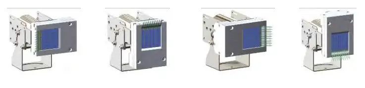
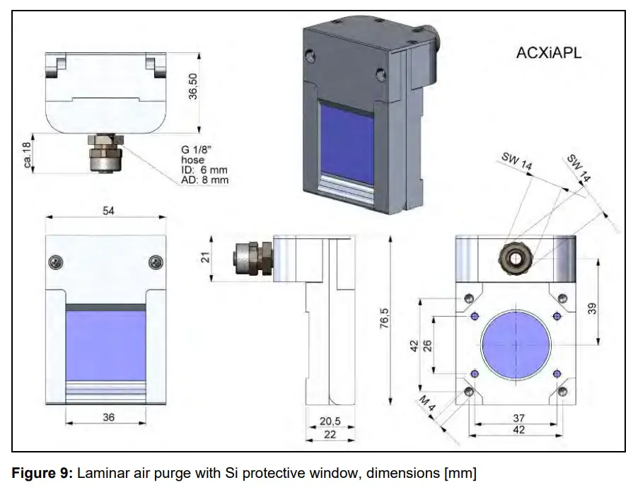
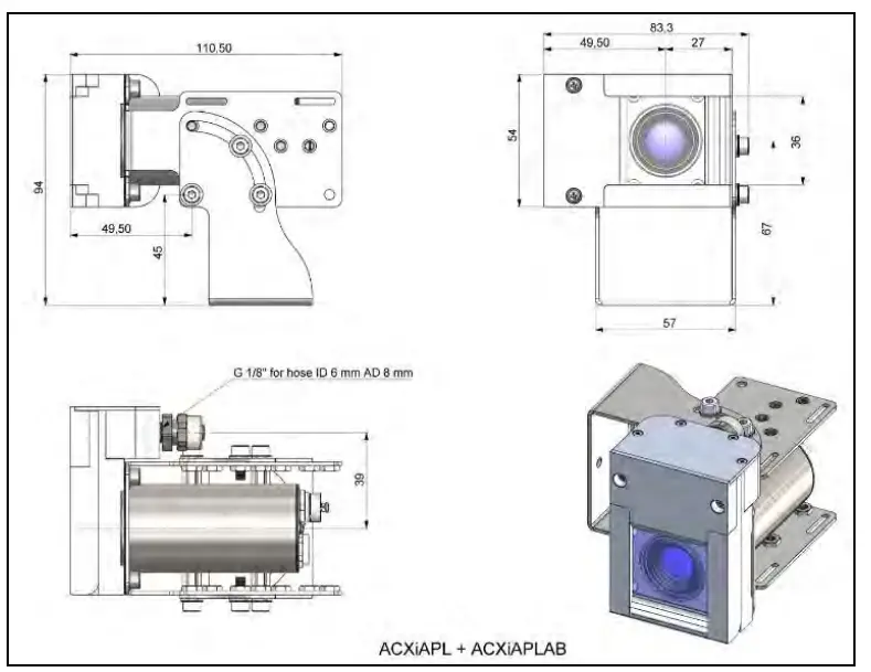 Figure 10: Laminar air purge with Si protective window (ACXIAPL) and mounting bracket (ACXIAPLAB), dimensions [mm]
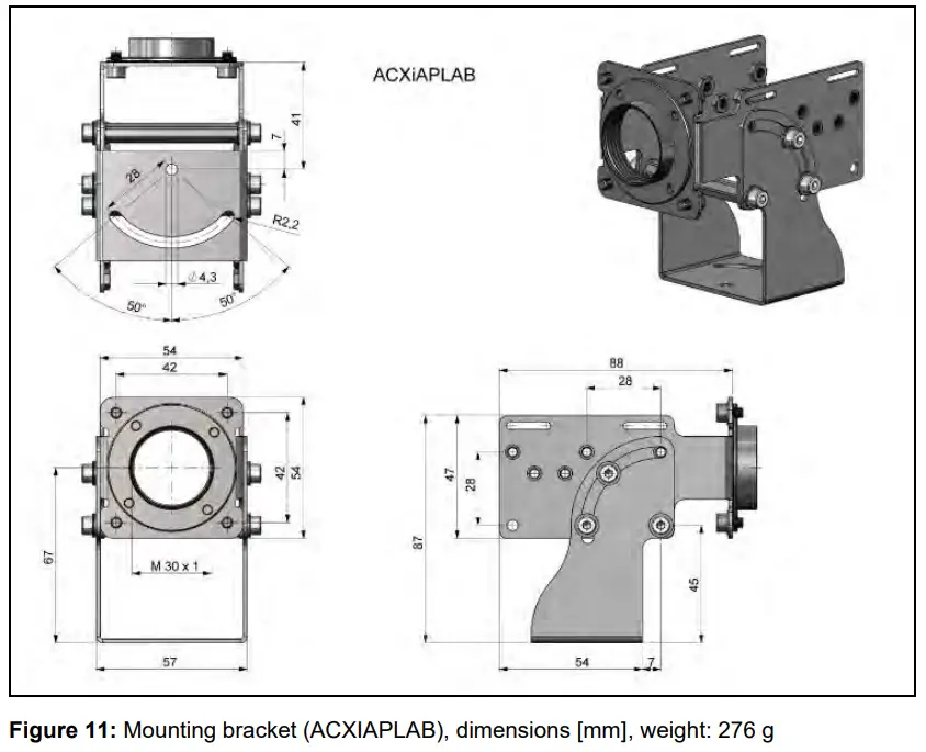
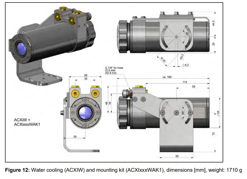
3.2.2 Water cooling
The IR camera is for application at ambient temperatures up to 50 °C. For applications at higher ambient temperatures we recommend the usage of the optional water cooled housing (operating temperature up to 250 °C) and the optional high temperature cable (operating temperature up to 250 °C).
- When using water cooling, a corresponding mounting kit (Part-No.: ACXIxxxWAKx) is required (WAK1: Usage without air purge, WAK2: Usage with air purge).
- Water flow rate: approx. 1-5 l/ min (Cooling water temperature should not exceed 30 °C)
- When using the water cooling the air purge (Part-No.: ACXIAPL) is recommended in order to avoid condensation
- Material: Stainless steel
- Weight: 1480 g
 | 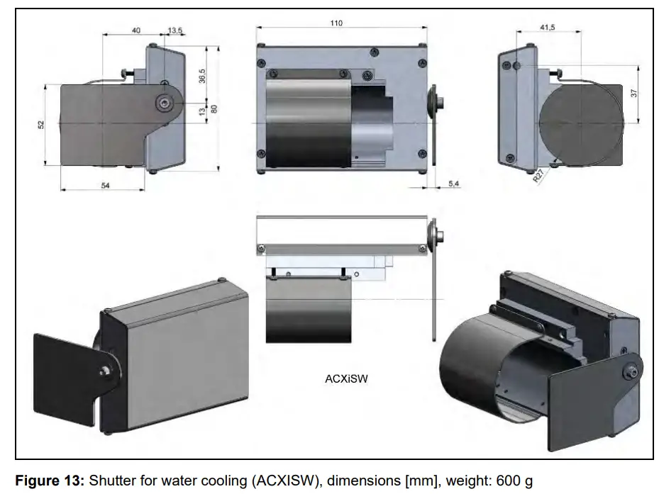 |
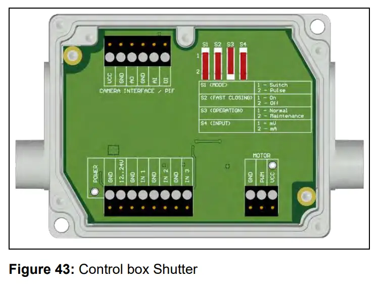
3.2.3 Shutter
To protect the optics of the camera, an optional shutter (closing mechanism) can be purchased. It is equipped with a servomotor that can open and close a mechanical lock as needed. The special feature of the shutter is not only the opening and closing, but also the complete seal in the closed state. This ensures that the shutter is completely closed and no dirt can get on the optics.
- The shutter has a 100 ms fast-closing mode.
- Complete seal when closed.
- Includes a control box for connections.
- Shutter can be used in combination with Process Interface (PIF).
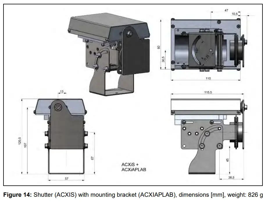
- The corresponding mounting bracket (Part-No.: ACXIAPLAB) is mandatory.
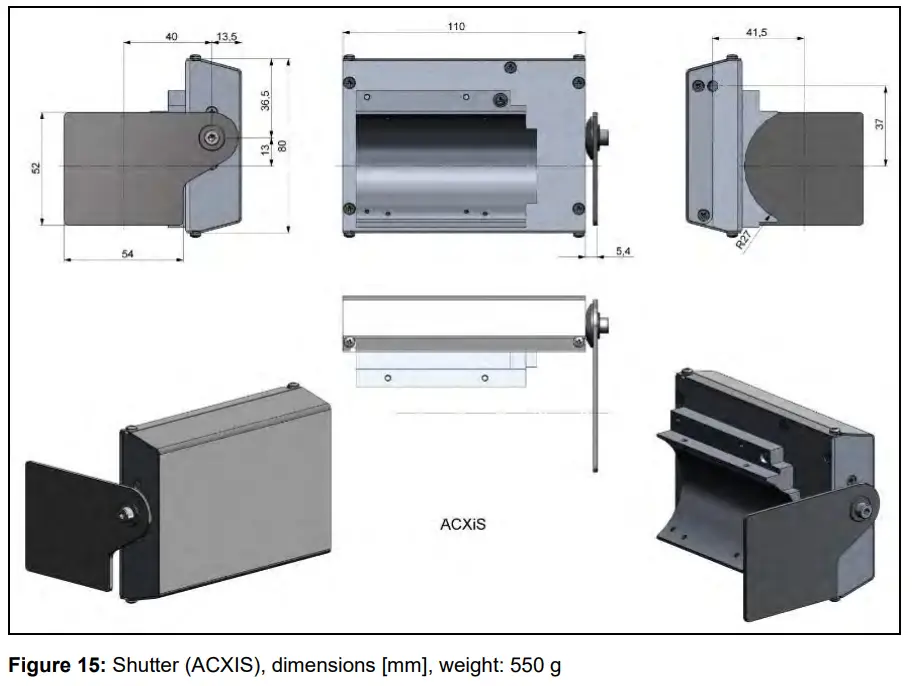
- Material: Stainless steel
- Weight: 550 g / 826 g Shutter with mounting bracket
- When using more than one shutter and the opening / closing of the shutter should be simultaneously, the switch S4 on one control box must be set to mA and the others to mV (see Figure 16).
- Ambient temperature: 0…60 °C (TAmb camera: 0…50 °C); with water cooled housing up to 250 °C
 |  |
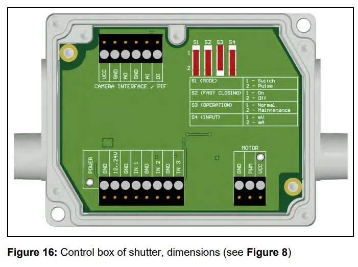
Power supply: 12-24 V
Upper terminal screw Connection for Process Interface (PIF)
Switch for different operation modes:
S1: Switching between switch operation and pulse operation
S2: Activation/deactivation of fastclosing mode
S3: Only for factory calibration (Switch must be at Normal)
S4: Switching between mV or mA input
Lower screw terminal: Connection for power supply, Inputs (Start/Stop signal) and Motor
Inputs (Start/Stop signal, max. 24 V, input is active LOW (open input = HIGH)):
IN 1: Trigger input for normal operation (S1)
IN 2: Currently no usage
IN 3: Trigger input for fast-closing mode (S2)
3.2.4 Combination of air purge, water cooling and shutter
It is possible to combine all three components (air purge, water cooling and shutter) with each other. It should be noted that there are differences between the Xi 80 and Xi 400/410. Various mounting kits (ACXIxxxWAKx) are available in combination with water cooling. The mounting bracket (ACXIAPLAB) is always required for air purge and shutter. For water cooling (ACXIW), the mounting bracket is included and does not have to be ordered separately.
| Part-No.:→ Combinations ↓ | ACXIAPL | ACXIAPLAB | ACXIS | ACXISW | ACXIW | ACXI80WAK1 | ACXI80WAK2 | ACXI400WAK1 | ACXI400WAK2 |
| Air purge | |||||||||
| Water cooling Xi 80 | |||||||||
| Water cooling Xi 400/410 | |||||||||
| Shutter | |||||||||
| Air purge and water cooling Xi 80 | |||||||||
| Air purge and water cooling Xi 400/410 | |||||||||
| Air purge and shutter | |||||||||
| Water cooling and shutter Xi 80 | |||||||||
| Water cooling and shutter Xi 400/410 | |||||||||
| Air purge, water cooling and shutter Xi 80 | |||||||||
| Air purge, water cooling and shutter Xi 400/410 |
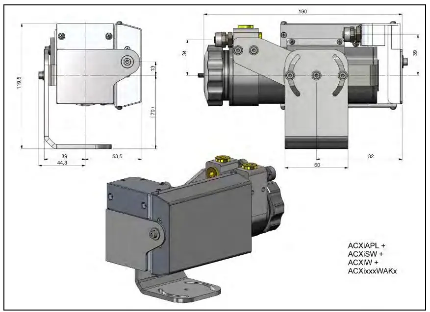 Figure 17: Air purge (ACXIAPL), water cooling (ACXIW), shutter (ACXISW) and appropriate mounting kit (ACXIxxxWAKx), dimensions [mm]
Components:
Figure 17: Air purge (ACXIAPL), water cooling (ACXIW), shutter (ACXISW) and appropriate mounting kit (ACXIxxxWAKx), dimensions [mm]
Components:
- Air purge
- Water cooling
- Shutter
- Mounting kit
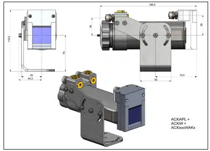 Figure 18: Air Purge (ACXIAPL), water Cooling (ACXIW) and appropriate mounting kit (ACXIxxxWAKx), dimensions [mm]
Components:
Figure 18: Air Purge (ACXIAPL), water Cooling (ACXIW) and appropriate mounting kit (ACXIxxxWAKx), dimensions [mm]
Components:
- Air purge
- Water cooling
- Mounting kit
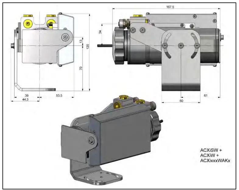 Figure 19: Water Cooling (ACXIW), Shutter (ACXISW) and appropriate mounting kit (ACXIxxxWAKx), dimensions [mm]
Components:
Figure 19: Water Cooling (ACXIW), Shutter (ACXISW) and appropriate mounting kit (ACXIxxxWAKx), dimensions [mm]
Components:
- Water cooling
- Shutter
- Mounting kit
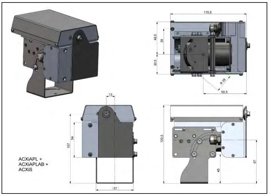 Figure 20: Air purge (ACXIAPL) with mounting bracket (ACXIAPLAB) and shutter (ACXIS), dimensions [mm]
Components:
Figure 20: Air purge (ACXIAPL) with mounting bracket (ACXIAPLAB) and shutter (ACXIS), dimensions [mm]
Components:
- Air purge
- Mounting bracket
- Shutter
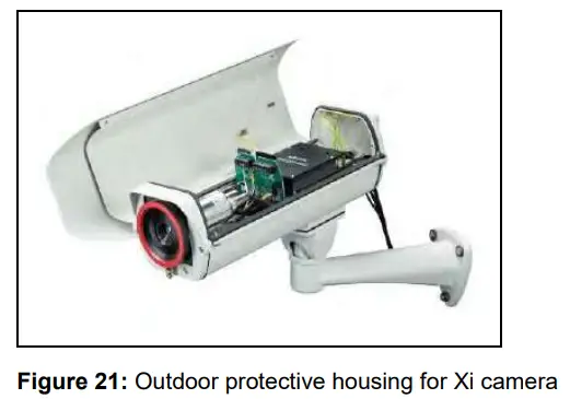
3.2.5 Outdoor protective housing
- The infrared camera Xi can also be used for outdoor applications by using the outdoor protective housing (Part-No.: ACXIOPH24).
- In addition, the industrial or stackable PIF (Part-No.: ACCJAPIPIFMA (Xi 400) or ACOPHXIPIF (Xi 80/410)) can be installed as an accessory without housing and a USB Server (Part-No.: ACPIUSBSGB).
- For detailed information see installation manual.

Electrical Installation
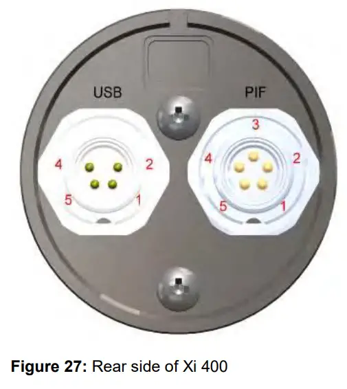
At the back side of the Xi there are the two connector plugs (see Figure 22 and Figure 23).
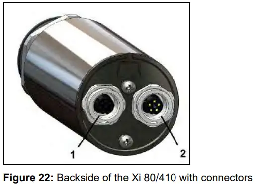
- Plug for USB / Ethernet1)/ PoE cable
- Plug for in- and outputs or RS485
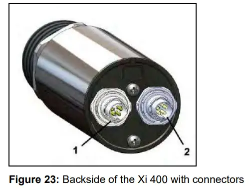
- Plug for USB cable
- Plug for PIF cable
1) When using the Ethernet connector, a 5…30 V DC power supply must be ensured via the terminal block
4.1 Process interface
4.1.1 Process interface Xi 80/410
The Xi 80/410 is equipped with an integrated process interface (cable with terminal block included in scope of supply), which can be programmed via the software as a direct analog input (AI), as a direct analog output (AO) in order to control the process or as an RS485 interface1). The signal level is 0-10 V for AI and 0/4-20 mA for AO.
The process interface can be activated via the software choosing the following options:
| Analog Input (AI): | Emissivity, ambient temperature, reference temperature, uncommitted value, flag control, triggered recording, triggered snapshots, triggered line-scanner, triggered event grabber, reset peak-/valley-hold, switch temperature range |
| Analog Output (AO): | Main measure area, measure area, internal temperature, flag status, recording status, line scan status, alarm, frame sync, fail-safe, external communication |
1) Direct out- and inputs are not available while using the RS485 interface
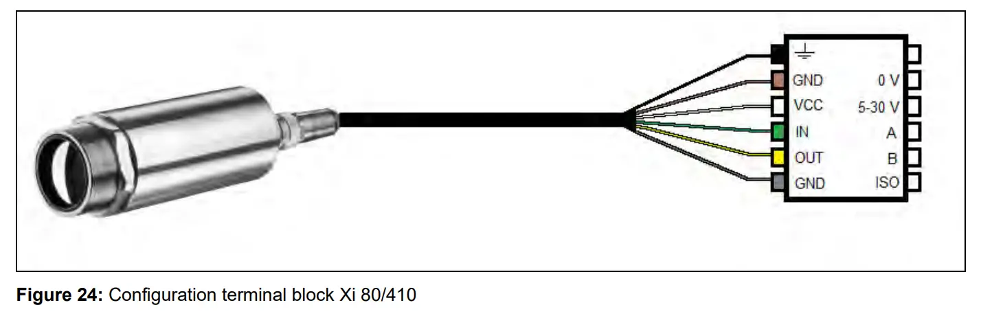
| Shield | Black | ||
| GND | 0 V | Ground | Brown |
| VCC | 5-30 V | Power1) | White |
| IN | A | Analog/Digital Input or RS485 (A) | Green |
| OUT | B | Analog Output or RS485 (B) | Yellow |
| GND | ISO | Isolated Ground for IN and OUT | Gray |
1) Power supply only necessary when using the Ethernet connection (without PoE) or self-sufficient operation
The Xi 80/410 provides the following direct inputs and outputs:
| Name | Description | max range/status |
| AI or DI | Analog input | 0-10 V 1) |
| Digital input (active-low = 0…0,6 V) | 24 V | |
| AO | Analog output Alarm output | 0/4-20 mA 0/4-20 mA |
1) The AI is designed for max. 24 V, the voltage level above 10 V is not interpreted
In addition to the above direct in- and outputs, the Xi 80/410 has an RS485 interface. This interface can be used to control the external industrial PIF.
4.1.2 Process interface Xi 400![]() The process interface (electronics within cable as well as industrial interface) must be powered separately (5-24 VDC). Before switching on the power the PIF cable must be connected to the camera.
The process interface (electronics within cable as well as industrial interface) must be powered separately (5-24 VDC). Before switching on the power the PIF cable must be connected to the camera.
The Xi is equipped with a process interface (cable with integrated electronics and terminal block), which can be programmed via the software as an Analog Input (AI) and Digital Input (DI) in order to control the camera or as an Analog Output (AO) in order to control the process. The signal level is always 0-10 V (DI = 24 V).
The process interface can be activated via the software choosing the following options:
| Analog Input (AI): | Emissivity, ambient temperature, reference temperature, uncommitted value, flag control, triggered recording, triggered snapshots, triggered line-scanner, triggered event grabber, reset peak-/valley-hold, switch temperature range |
| Analog Output (AO): | Main measure area, measure area, internal temperature, flag status, recording status, line scan status, alarm, frame sync, fail-safe, external communication |
| Digital Input (DI): | Flag control, triggered recording, triggered snapshots, triggered line-scanner, triggered event grabber, reset peak-/valley-hold, switch temperature range |
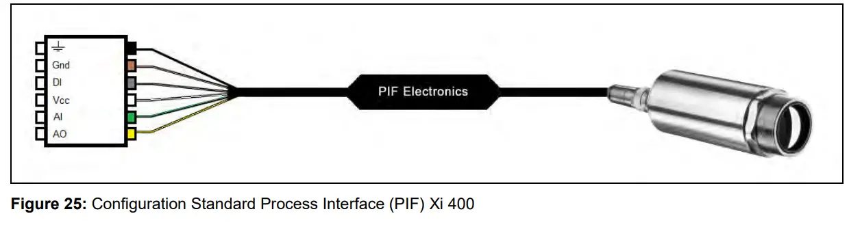
| Shield | Black | |
| Gnd | Ground | Brown |
| DI | Digital Input | Gray |
| Vcc | Power supply, 5…24 V DC | White |
| AI | Analog Input | Green |
| AO | Analog Output | Yellow |
The standard process interface provides the following inputs and outputs:
| Name | Description | max range/status |
| AI | Analog input | 0-10 V 1) |
| DI | Digital input (active-low = 0…0,6 V) | 24 V |
| AO | Analog output Alarm output | 0/4-20 mA 0/4-20 mA |
1) Depending on supply voltage; for 0-10 V on the AO the PIF has to be powered with min. 12 V.
1)The AI is designed for max. 24 V, the voltage level above 10 V is not interpreted
4.1.3 PIN allocation Xi 80/410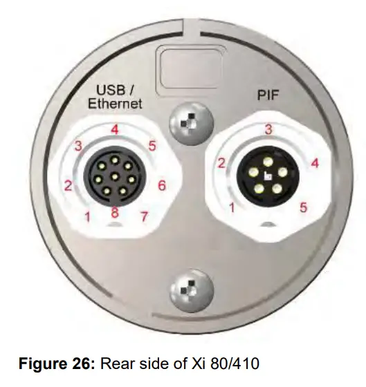
| USB | Ethernet | PIF |
| 1 VCC | 1 VCC | |
| 2 D + | 2 RS485 or AO | |
| 3 D – | 3 RS485 or AI | |
| 4 | Tx + | 4 GND |
| 5 | Tx – | 5 GND-ISO |
| 6 | Rx + | |
| 7 | Rx – | |
| 8 GND |
4.1.4 PIN allocation Xi 400
| USB | PIF |
| 1 VCC | 1 INT |
| 2 GND | 2 SDA (I²C) |
| 4 D – | 3 SCL (I²C) |
| 5 D + | 4 DGND |
| 5 3,3 V (Out) |
If the process interface of the camera is directly connected to external hardware1) (without using the supplied PIF cable) an activation of the field „Support proprietary PIF cable” in the menu Tools/ Configuration/ Device (PIF) in the PIX Connect software is necessary.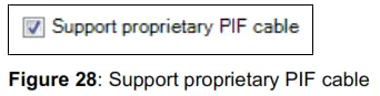
![]() Consider that the input of the PIF is not protected if there is a direct PIF connection! A voltage > 3 V on the INT pin will destroy the device!
Consider that the input of the PIF is not protected if there is a direct PIF connection! A voltage > 3 V on the INT pin will destroy the device!
1) We recommend using only a switching contact between INT and DGND as external hardware (button, relay).
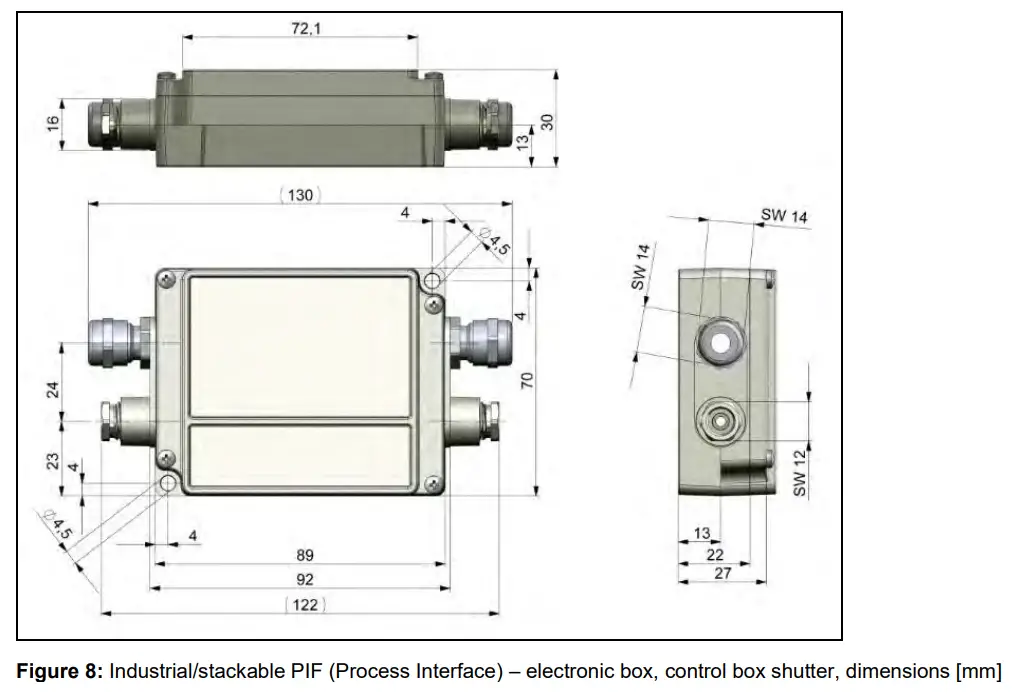
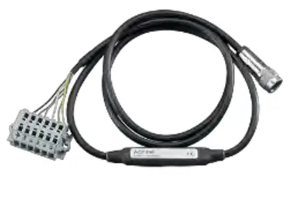
4.1.5 Industrial Process Interface for Xi 80/410 (optional)
For use in industrial environment the industrial process interface with 500 V ACRMS isolation voltage between Xi and process is available (connection box with IP65, 5 m, 10 m or 20 m standard or high temperature cable for camera connection, terminal for process integration). [►Appendix F – Wiring diagrams PIF]
Pin assignment PIF cable (industrial process interface)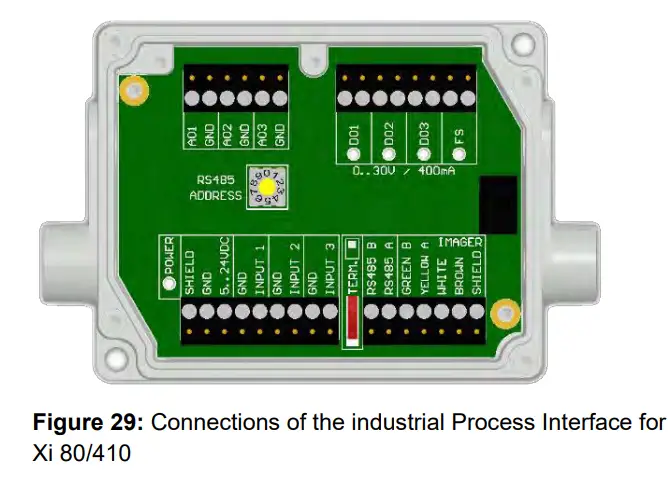
| GREEN | RS485 B |
| YELLOW | RS485 A |
| WHITE | 12 V |
| BROWN | GND |
| SHIELD | GND |
The process interface can be activated via the software choosing the following options:
| Analog Input (AI): | Emissivity, ambient temperature, reference temperature, uncommitted value, flag control, triggered recording, triggered snapshots, triggered line-scanner, triggered event grabber, reset peak-/valley-hold, switch temperature range |
| Analog Output (AO): | Main measure area, measure area, internal temperature, flag status, recording status, line scan status, alarm, frame sync, fail-safe, external communication, autonomous status |
| Digital Output (DO): | Flag status, recording status, line scan status, alarm, frame sync, fail-safe, external communication, autonomous status |
The industrial process interface provides the following in- and outputs:
| Name | Description | max range1)/status |
| INPUT 1 / 2 / 3 | Analog or digital input | 0-10 V 2) |
| AO1 / 2 / 3 | Analog output 1, 2 and 3 Alarm output 1, 2 and 3 | 0-10 V 0/4-20 mA |
| DO1 / 2 / 3 | Relay output 1, 2 and 3 | open/ closed (red LED on) / 0…30 V, 400 mA |
| FS | Fail-safe relay | open/ closed (green LED on)/ 0…30 V, 400 mA |
1) depending on supply voltage; for 0-10 V on the AO the PIF has to be powered with min. 12 V.
2) the AI is designed for max. 24 V, the voltage level above 10 V is not interpreted![]() The industrial PIF has a maximum of 3 analog outputs. To use more outputs, you can cascade up to three PIFs, allowing you to use up to 9 analog or alarm outputs in total.
The industrial PIF has a maximum of 3 analog outputs. To use more outputs, you can cascade up to three PIFs, allowing you to use up to 9 analog or alarm outputs in total.
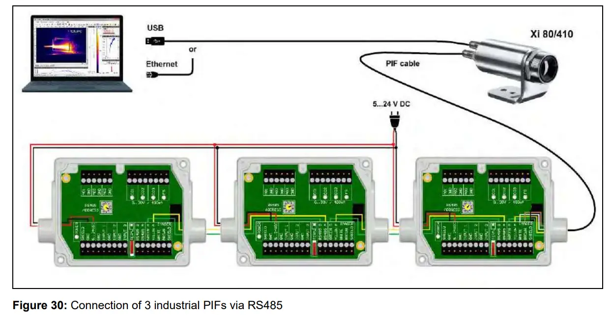
![]() Each stackable industrial PIF must have its own RS485 address. The address must be set directly on the board. For the PIF which is the furthest away the 120R switch (TERM. – Termination) has to be set.
Each stackable industrial PIF must have its own RS485 address. The address must be set directly on the board. For the PIF which is the furthest away the 120R switch (TERM. – Termination) has to be set.![]() The RS485 interface is defined for a length of 500 m.
The RS485 interface is defined for a length of 500 m.
The process interface has an integrated fail-safe mode. This allows to control conditions like interruption of cables, shut-down of the software etc. and to give out these conditions as an alarm. The time constant of the fail-safe is 1.5 seconds.
| Controlled conditions on camera and software | Standard Process interface ACXIIOCB1 | Industrial Process interface ACXIPIFCBxx |
| Interruption USB cable to camera | – | |
| Interruption data cable camera – PIF | ||
| Interruption power supply PIF | ||
| Shut-down of PIX Connect software | – | |
| Crash of PIX Connect software | – | – |
| Fail-Safe-Output | 0 mA at analog output (AO) | open contact (fail-safe relay)/ green LED off |
4.1.6 Industrial Process Interface for Xi 400 (optional)
For use in industrial environment the industrial process interface with 500 V ACRMS isolation voltage between Xi and process is available (connection box with IP65, 5 m, 10 m or 20 m standard or high temperature cable for camera connection, terminal for process integration). [►Appendix F – Wiring diagrams PIF]
Pin assignment PIF cable (industrial process interface)
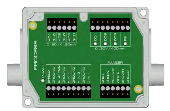 Figure 31: Connections of the industrial Process Interface for Xi 400
| GREY | Interrupt |
| GREEN | SCL (I²C) |
| YELLOW | SDA (I²C) |
| WHITE | 3.3 V |
| BROWN | GND |
| SHIELD | GND |
The process interface can be activated via the software choosing the following options:
| Analog Input (AI): | Emissivity, ambient temperature, reference temperature, uncommitted value, flag control, triggered recording, triggered snapshots, triggered line-scanner, triggered event grabber, reset peak-/valley-hold, switch temperature range |
| Analog Output (AO): | Main measure area, measure area, internal temperature, flag status, recording status, line scan status, alarm, frame sync, fail-safe, external communication |
| Digital Input (DI): | Flag control, triggered recording, triggered snapshots, triggered line-scanner, triggered event grabber, reset peak-/valley-hold, switch temperature range |
The industrial process interface provides the following inputs and outputs:
| Name | Description | max range1)/ status |
| A IN 1 / 2 | Analog input 1 and 2 | 0-10 V 2) |
| D IN 1 | Digital input (active-low = 0…0,6 V) | 24 V |
| AO1 / 2 / 3 | Analog output 1, 2 and 3 Alarm output 1, 2 and 3 | 0/4-20 mA |
| DO1 / 2/ 3 | Relay output 1, 2 and 3 3) | open/ closed (red LED on) / 0…30 V, 400 mA |
| FS | Fail-safe relay | open/ closed (green LED on)/ 0…30 V, 400 mA |
1) depending on supply voltage; for 0-20 mA on the AO the PIF has to be powered with min. 5V < (1.5 + working resistance * 0.021) < 24 V; Example: RLoad = 500 ohm → Umin = 1.5 + 500 * 0.021 = 12 V, RLoad = 100 ohm → Umin = 1.5 + 100 * 0.021 = 3.6 V → min. 5 V
2)the AI is designed for max. 24 V, the voltage level above 10 V is not interpreted
3) active if AO1, 2 or 3 is/ are programmed as alarm output![]() The alarm output can be configured as a threshold between 0-4 mA for no alarm and between 10-20 mA as alarm. For values outside the respective range, the relay does not switch on the DO.
The alarm output can be configured as a threshold between 0-4 mA for no alarm and between 10-20 mA as alarm. For values outside the respective range, the relay does not switch on the DO.
The process interface has an integrated fail-safe mode. This allows to control conditions like interruption of cables, shut-down of the software etc. and to give out these conditions as an alarm. The time constant of the fail-safe is 1.5 seconds.
| Controlled conditions on camera and software | Standard Process interface ACPIPIF | Industrial Process interface ACPIPIFMACBxx |
| Interruption USB cable to camera | ||
| Interruption data cable camera – PIF | ||
| Interruption power supply PIF | ||
| Shut-down of PIX Connect software | ||
| Crash of PIX Connect software | – | |
| Fail-Safe-Output | 0 V at analog output (AO) | open contact (fail-safe relay)/ green LED off |
4.2 Example for a Fail-Safe monitoring of the Xi with a PLC
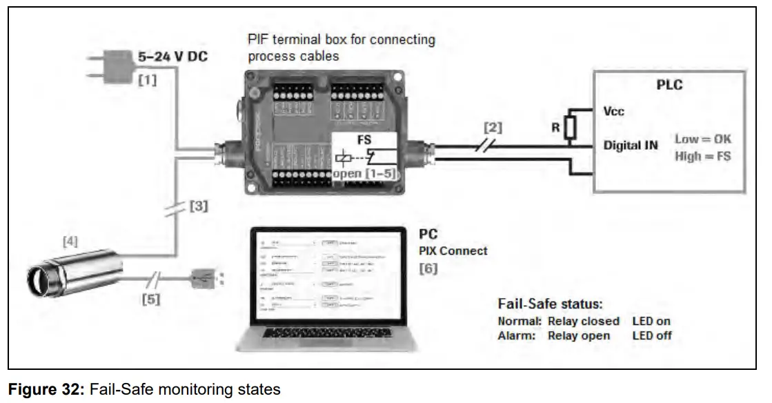
Fail-Safe monitoring states
- Breakdown of PIF power supply
- Cable break of fail-safe cable
- Interruption of cable Xi-PIF
- Malfunction of Xi
- Breakdown of Xi power supply/ Interruption of USB cable
- Malfunction of PIX Connect software
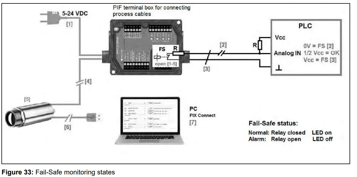
Fail-Safe monitoring states
- Breakdown of PIF power supply
- Cable break of fail-safe cable
- Short circuit of fail-safe cable
- Interruption of cable Xi-PIF
- Malfunction of Xi
- Breakdown of Xi power supply/ Interruption of USB cable
- Malfunction of PIX Connect software
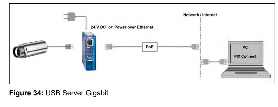
4.3 USB cable extension for Xi 400
The maximum USB cable length is 20 m. For greater distances between Xi 400 and computer or for standalone solutions the optional USB Server Gigabit (Part No.: ACPIUSBSGB) is provided:
Functions
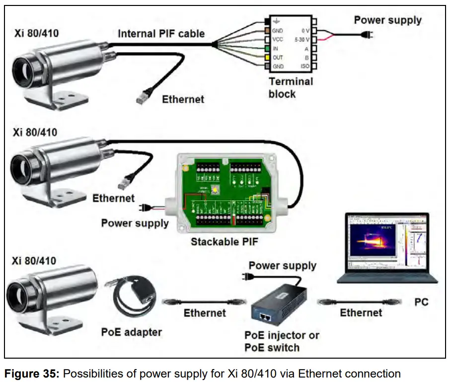
5.1 Ethernet Xi 80/410
The Xi 80/410 has a direct Ethernet interface. The advantage is cable lengths of up to 100 m. For example, a switch can be used to extend the distances. The associated Ethernet cable (Order No.: ACXIETCBx) must be ordered separately. Ethernet is supported from software version Rel. 3.2.3020.0 and firmware 3008.
Using the Ethernet connection, the device must be supplied with power. This can be done either via:
- the internal PIF cable via the terminal block (5-30 V)
- the stackable PIF (5-24 V, Order No.: ACXIPIFCBx)
- PoE (Power over Ethernet)
![]() For the PoE variant, a PoE adapter (Order No.: ACXIETPOECB1) and a PoE injector (Order No.: ACPIPOE) or PoE switch (e.g. Netgear GS510TLP) are also required.
For the PoE variant, a PoE adapter (Order No.: ACXIETPOECB1) and a PoE injector (Order No.: ACPIPOE) or PoE switch (e.g. Netgear GS510TLP) are also required.
5.1.1 Ethernet setup (Point-to-Point-Connection)
After connecting the Ethernet cable to the camera and the PC, the first thing you need to do is to make the network settings on the PC.![]() The devices are delivered with the following factory settings:
The devices are delivered with the following factory settings:
- IP address camera: 192.168.0.101
- IP address PC: 192.168.0.100
- Port number: 50101
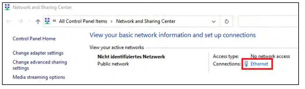
To do this, go to Control Panel and open the Network and Sharing Center. Go on LAN connection.
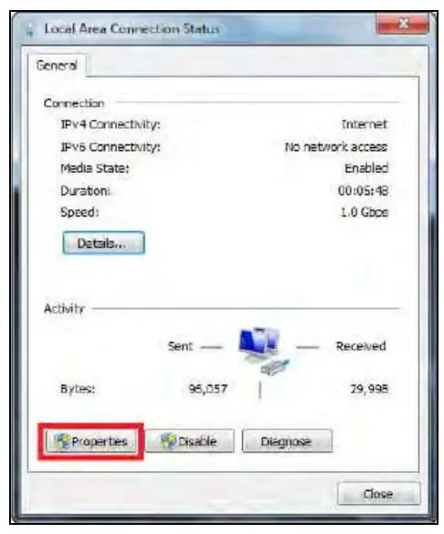
Click on Properties.
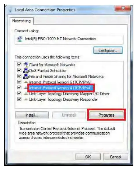
Mark Internet protocol Version 4 (TCP/IPv4) and go to Properties again
In the register card General enable the checkbox Use the following IP address. Now enter a user defined IP address for your PC (192.168.0.100). This must be identical to the address set in the PIX Connect software.
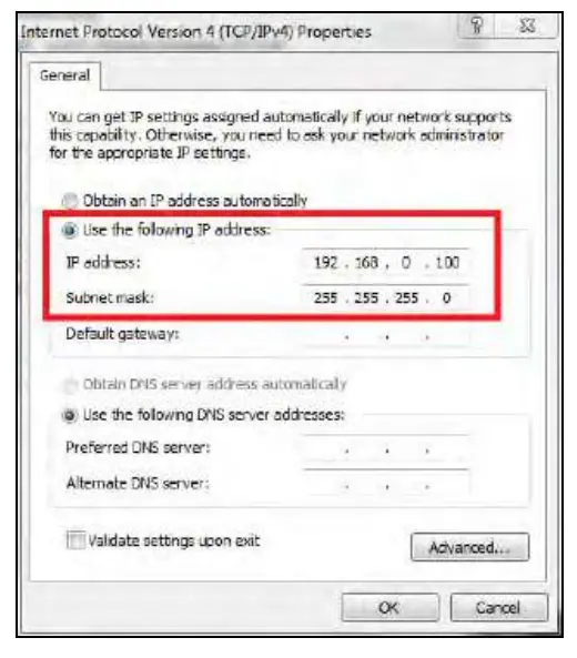
Then close all windows with OK. The network settings on the PC are complete.
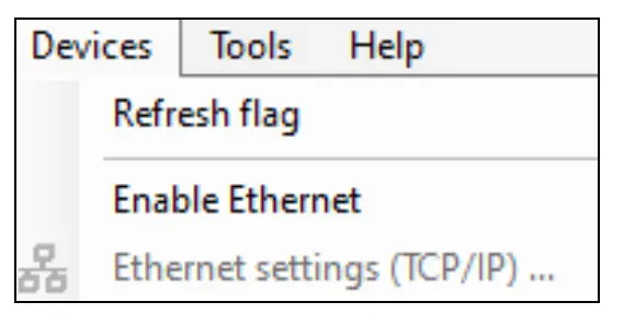
Now start the PIX Connect software and activate the Ethernet function. To do this, go to the menu Devices and Enable Ethernet.
![]() When a Windows Firewall window appears make sure to select allow all three network parts (domain, private, public) in order to allow the communication with the device.
When a Windows Firewall window appears make sure to select allow all three network parts (domain, private, public) in order to allow the communication with the device.
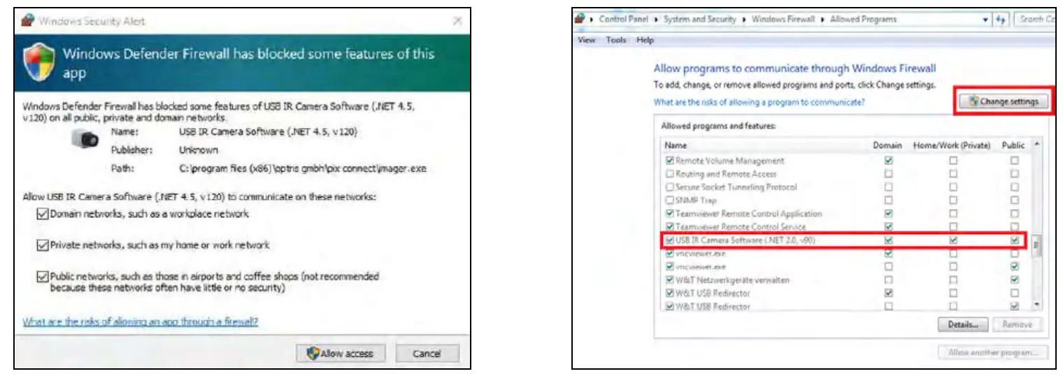
![]() The approval of programs can also be activated afterwards in the Windows Firewall settings of the PC (under Windows Firewall and Allow a program or feature through Windows Firewall).
The approval of programs can also be activated afterwards in the Windows Firewall settings of the PC (under Windows Firewall and Allow a program or feature through Windows Firewall).
The device is now ready for the Ethernet connection and is listed in the menu under Devices. The camera is identified by a network icon and the network address and port number. Select the device. A connection to the device is established and the temperature measurement can begin.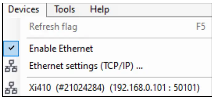 To change the address settings, go to Devices and Ethernet settings (TCP/IP). The address for the device is assigned under Device address. This must have a different address (last block) to the other participant (e.g., PC) (Send to address (local computer)). It is important that the network part (first three blocks) must be identical for both addresses. The address range of the individual blocks can be between 0 and 255.
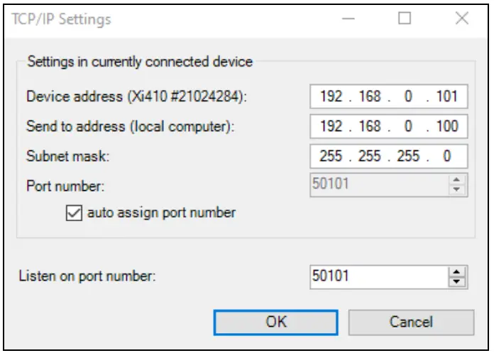
Additionally, a separate port number must be configured. The selected number can be between 1 and 65535.
If several cameras with different port numbers are connected and a specific camera is to be communicated with, the corresponding camera can be determined via Listen on port number.![]() The port range used should be between 49152 … 65535. When using other ports, it could be that they are already reserved or assigned.
The port range used should be between 49152 … 65535. When using other ports, it could be that they are already reserved or assigned.
When using multiple Xi 80/410 cameras in a network, the data rate must be considered:
➢ Switch with 100 Mbps: approx. 17 devices (Xi 80), approx. 2 devices (Xi 410 with 25 Hz)
➢ Switch with 1000 Mbps: approx. 170 devices (Xi 80), approx. 26 devices (Xi 410 with 25 Hz)![]() In addition to the data rate also make sure the power performance of the PC is high enough. Each device used requires its own instance.
In addition to the data rate also make sure the power performance of the PC is high enough. Each device used requires its own instance.
5.2 Autonomous operation Xi 80/410
A special feature of the Xi 80/410 is the autonomous operation. There is no need for a permanent connection to the PIX Connect software. Only a few settings must be set in advance in the software.
To do this, connect the PIF and Ethernet or USB cables to the device. Then connect the Xi to your PC and start the PIX Connect software (see 7 Software PIX Connect).
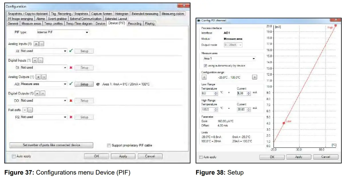
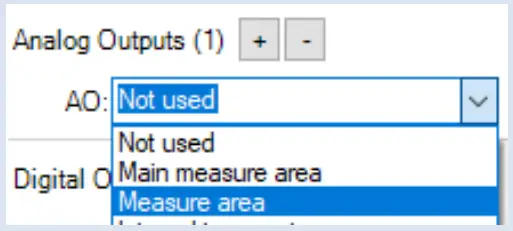
Position and focus (see 2.4 Optical specifications) the camera so that your object to be measured is perfectly visible in the image. First define the desired measurement area with the corresponding mode you want to output.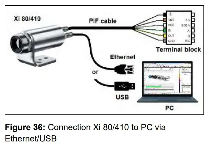 Now go to the configuration menu on Device (PIF). There you first select the PIF type (in this case: Internal PIF). Then select under Analog Outputs (AO) the function that is to be output autonomously. Then press Setup, make your settings, and make sure that the checkbox is set to using autonomously by device. By pressing the OK button an @ sign can be found in the configuration menu Devices (PIF), which indicates the autonomous operation.
Only for Xi 410
When using the Xi 410 camera, an important additional setting must be made for autonomous operation. When all the configurations have been made, it is important to write them to the device. This is done in the menu under Devices and Set configuration to device.
If the device is reconnected to a PC after autonomous operation and the settings are to be transferred from the device to the software, this is done in the menu under Devices and Get configuration from device.
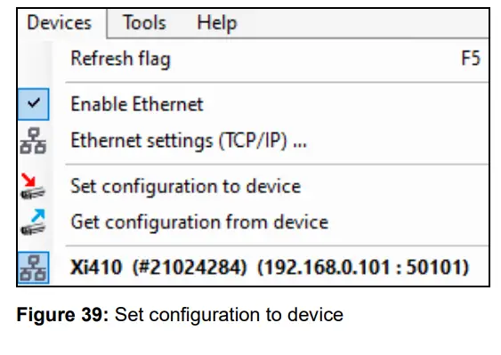
![]() An arrow marked in red
An arrow marked in red ![]() means that the configuration is different between the camera and the software. As soon as the configuration is loaded into the device, the arrow appears blue
means that the configuration is different between the camera and the software. As soon as the configuration is loaded into the device, the arrow appears blue ![]() .
.
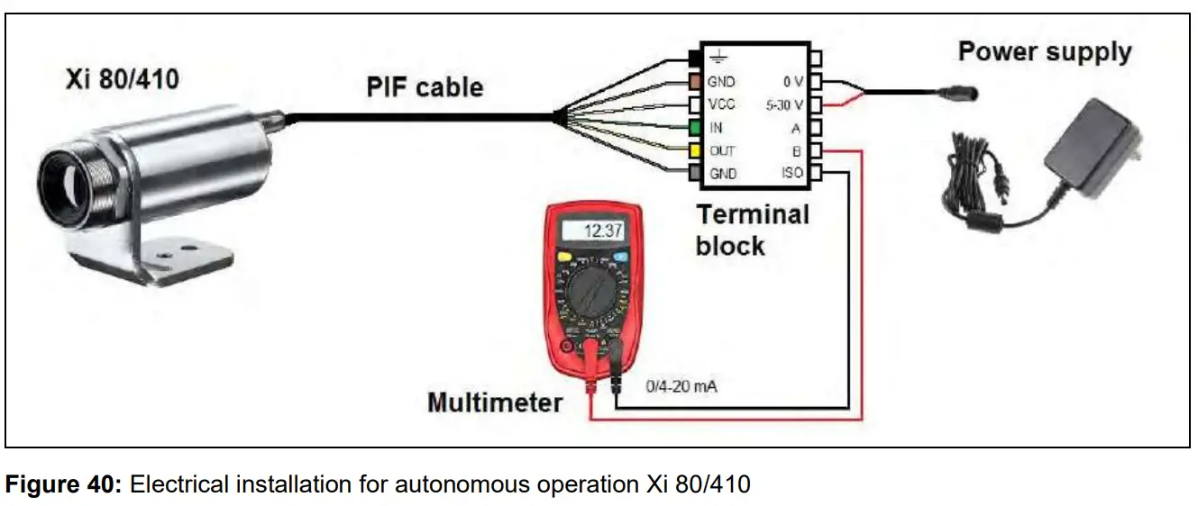
In general, these are all the settings that must be set in the PIX Connect software in order to operate the device autonomously. You can now close the software and then disconnect the Ethernet or USB cable. To start the device autonomously, a 5-30 V power supply must be connected to the terminal block. Now the used input/output must be connected. The resulting value can be displayed for example on a multimeter (see Figure 40).
- Autonomous operation also works via the industrial/stackable PIF of the Xi 80. The device is powered by the power supply of the PIF.
- Up to 9 measure areas (for Xi 80 with firmware 3013 or higher) and up to 3 measure areas (Xi 410) can be output autonomously. The use of three stackable PIFs is required. Three analog outputs are possible per stackable PIF. The response time is 20 ms for Xi 80 and 640 ms for Xi 410.
Note: Several measuring areas can be combined into one measuring area via a so-called super area. - Autonomous mode cannot be set using the Main measure area function (configuration menuDevice (PIF)). To output a measure area autonomously, the function Measure area must be used.

5.2.1 Hot- / Coldspot function in autonomous operation
The setting for a hot- or coldspot in autonomous mode differs from the general procedure. Marking a measure area as hot- or coldspot does not work. Instead, a user defined rectangle must be selected under the tab measure areas of the configuration dialog. In addition, under Mode, you must set whether the maximum (for hotspot) or minimum (for coldspot) should be output.
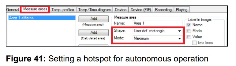
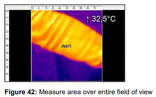
For a hot- or coldspot output in the full field of view of the camera, the user defined rectangle must also fill out this size.
Note: Predefined Layout in the software available under Tools and Layouts: Xi 80 Hot spot autonomous or Xi 410 Hot spot autonomous.
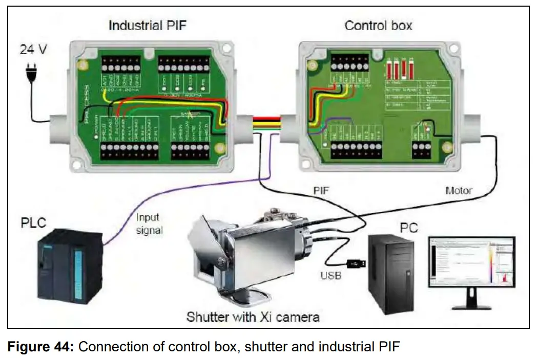
5.3 Use of Shutter
The shutter system is supplied with a control box (for pin assignment, see also Figure 16). The servo motor of the shutter is connected to this control box. There are several ways to operate the control box. For all listed options, an input signal (IN 1) must be connected. This input signal can, for example, come from a PLC, a light barrier or a sensor. This signal opens and closes the shutter. A second input signal (IN 3) can be used to realize a fast-closing mode. The closing time in this mode is only 100 ms.
By using the process interface (PIF), the input signal to the software can be passed on and used as a trigger signal in the software. For example, an automatic recording can take place when the shutter is opened.
The process interface cable supplied with the cameras can be connected directly to the control box (upper terminal block: CAMERA INTERFACE/PIF). Alternatively, the separately obtained industrial or stackable PIF can also be connected to the control box (if several outputs and inputs are used). In this case, the outputs and inputs used (e.g. AO from control box with AO from PIF) must be connected with each other.![]() When using more than one shutter and the opening/closing of the shutter should be simultaneously, the switch S4 on one control box must be set to mA and the others to mV (see Figure 43).
When using more than one shutter and the opening/closing of the shutter should be simultaneously, the switch S4 on one control box must be set to mA and the others to mV (see Figure 43).
5.3.1 Settings in PIX Connect Software
After the hardware installation (connection control box shutter and PIF) the following settings can be made in the software:
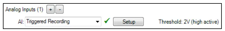
- Automatic Recording: By opening the shutter through input signal IN 1, an automatic recording can be started. For this, the AI must be configured to Triggered Recording in the software in the configuration menu Device (PIF).

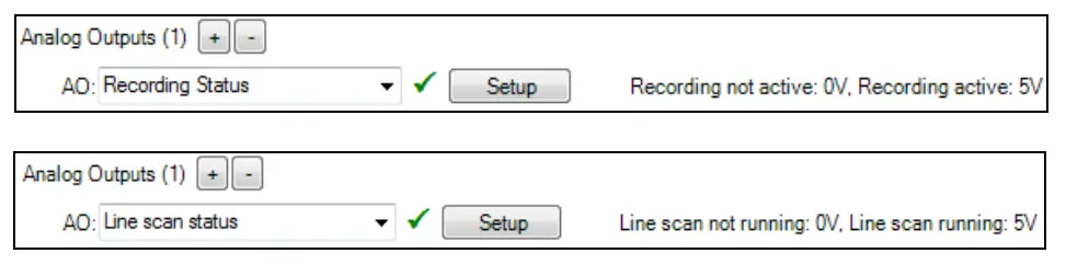
- Close shutter after recording/line scan: When the recording is finished, the shutter can be closed by an analog signal. To do this, in the software in the configuration menu Device (PIF) of the AO must be configured for Recording Status. If the shutter is to be closed after a line scan, Line scan status must be selected.

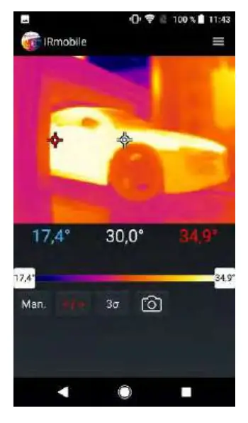
IRmobile App
The imagers have a direct connection to an Android smartphone or tablet. All you must do is download the IRmobile app for free in the Google Play Store. This can also be done via the QR code. An IRmobile app connector is recommended for connection to the device (Xi 80/410: Part-No.: ACXI80IACM (micro-USB) or ACXI80IACC (USB-C), Xi 400: PartNo.: ACPIIACM (micro-USB) or ACPIIACC (USB-C).

 https://play.google.com/store/apps/details?id=com.optris.irmobile&hl=en
With IRmobile you can monitor and analyze your infrared temperature measurement directly on a connected smartphone or tablet. All you need is an Optris infrared camera. This app runs on most Android (5 or higher) devices with a micro-USB port or USB-C port that supports USB OTG (On The Go). The app is easy to use:
After you have connected your camera to the micro-USB port or USB-C port of your smartphone or tablet, the app launches automatically. The calibration files are automatically downloaded from the internet. The device is powered by your smartphone. A hotspot indicates the hottest pixel in the image and a coldspot the coldest pixel in the image.
IRmobile app features:
➢ Live infrared image with automatic hot-/ and coldspot search
➢ Changing the color palette, scaling and temperature range
➢ Change of temperature unit: Celsius or Fahrenheit
➢ Setting of temperature range scaling (Manual, Min/Max, 3 sigma)
➢ Creating a snapshot
➢ Integrated simulator
IRmobile supported for:
➢ Optris IR cameras: Xi and PI series
➢ Optris pyrometers: Compact series, high performance series and videothermometers
➢ For Android 5 (or higher) devices with a micro-USB port or USB C port that supports USB OTG (On The Go)
Software PIX Connect
Minimum system requirements:
- Windows 7, Windows 8, Windows 10
- USB interface
- Hard disc with at least 30 MByte of free space
- At least 128 MByte RAM
![]() A detailed description is provided in the software manual on the USB stick. See also Help menu in the PIX Connect software (Help → Documentation).
A detailed description is provided in the software manual on the USB stick. See also Help menu in the PIX Connect software (Help → Documentation).![]() Alternatively, the software can also be downloaded
Alternatively, the software can also be downloaded
7.1 Installation and initial start-up
- All drivers are booted via Windows OS automatically. A driver installation is not necessary.
- By default, the program starts automatically in the installed language.
- Insert the included USB stick into the according port on your computer.
- Please start Setup.exe. Follow the instructions of the wizard until the installation is finished.
The installation wizard places a launch icon on the desktop and in the start menu: Start\Programs\Optris GmbH\PIX Connect - To connect the camera to the PC, plug the USB cable to the camera first. Afterwards connect it with the PC (to disconnect the camera and the computer remove the USB cable from the computer first and then disconnect it from the camera).
- Start the software.
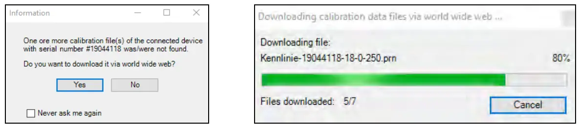
At the initial start the software asks for the calibrations files which are available via internet or on the USB stick (only for Xi 400). With the Xi 80/410, the calibration files are already included in the device. - Install the calibration files at first start of the software (only necessary for Xi 400).
 After the calibration files have been installed the live image from the camera is shown inside a window on your PC screen.
 - Choose the desired language in the menu Tools → Language.
- Adjust the focus of the image by using the distance function in the software (Menu View/ Windows/ Distance or over the icon
 ):
):
 After the calibration files have been installed the live image from the camera is shown inside a window on your PC screen.
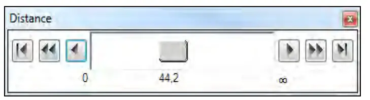
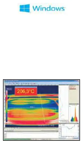
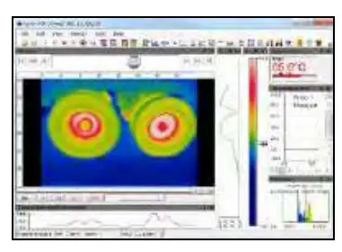
7.2 Software window
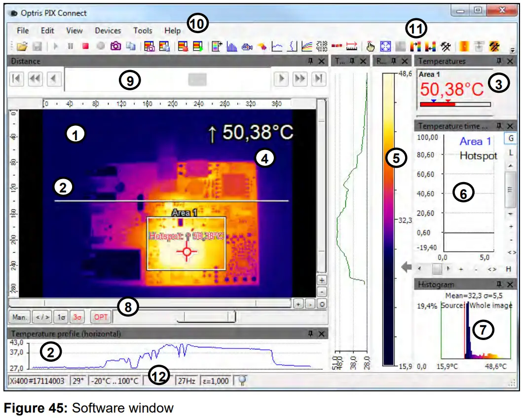
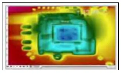
- IR image from the camera
- Temperature profile: Shows the temperatures along max. 2 lines at any size and position in the image.
- Control displays: Displays all temperature values in the defined measure areas like Cold Spots, Hot Spots, temperature at cursor, internal temperature and chip temperature.
Alarm settings: Bar showing the defined temperature thresholds for low alarm value (blue arrow) and high alarm value (red arrow). The color of numbers within control displays changes to red (when temp. above the high alarm value) and to blue (when temp. below the low alarm value). - Temperature of measure area: Analyses the temperature according to the selected shape, e.g. average temperature of the rectangle. The value is shown inside the IR image and the control displays.
- Reference bar: Shows the scaling of temperature within the color palette.
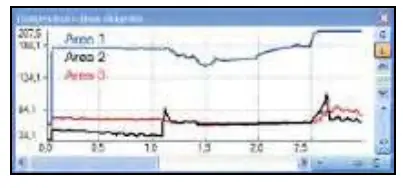
- Temperature time diagram: Shows the temperature curves over time for selectable region of interest (ROI)
- Histogram: Shows the statistic distribution of single temperature values.
- Automatic / manual scaling of the palette (displayed temperature range): Man., </> (min, max), 1σ : 1 Sigma, 3σ : 3 Sigma, OPT: Palette optimization
- Distance function: Adjustment of the motor focus to focus the IR picture
- Menu and Toolbar (Icons)
- Icon enabling switching between color palettes
- Status bar: Serial number, optic, temperature range, cursor position, device framerate/ display framerate, emissivity, ambient temperature, flag status
7.3 Basis features of the software PIX Connect
Extensive infrared camera software
- No restrictions in licensing
- Modern software with intuitive user interface
- Remote control of camera via software
- Display of multiple camera images in different windows
- Compatible with Windows 7, 8 and 10
High level of individualization for customer specific display
- Various language option including a translation tool
- Temperature display in °C or °F
- Different layout options for an individual setup (arrangement of windows, toolbar)
- Range of individual measurement parameter fitting for each application
- Adaption of thermal image (mirror, rotate)
- Individual start options (full screen, hidden, etc.)
Video recording and snapshot function (IR)
- Recording of video sequences and detailed frames for further analysis or documentation
- Adjustment of recording frequency to reduce data volume
- Display of snapshot history for immediate analysis
Extensive online and offline data analysis
- Analysis supported by measurement fields, hot and cold spot searching, image subtraction
- Real time temperature information within main window as digital or graphic display (line profile, temperature time diagram)
- Slow motion repeat of radiometric files and analysis without camera being connected
- Editing of sequences such as cutting and saving of individual images
- Various color palettes to highlight thermal contrasts
Automatic process control
- Individual setup of alarm levels depending on the process
- Definition of visual or acoustic alarms and analog data output
- Analog and digital signal input (process parameter)
- External communication of software via COM-Ports and DLL
- Adjustment of thermal image via reference values
Temperature data analysis and documentation
- Triggered data collection
- Radiometric video sequences (*.ravi) radiometric snapshots (*.tiff)
- Text files including temp. information for analysis in Excel (*.csv, *.dat)
- Data with color information for standard programs such as Photoshop or Windows Media Player (*.avi, *.tiff)
- Data transfer in real time to other software programs DLL or COM-Port interfaces
Basics of Infrared Thermometry
Depending on the temperature each object emits a certain amount of infrared radiation. A change in the temperature of the object is accompanied by a change in the intensity of the radiation.
Searching for new optical material William Herschel by chance found the infrared radiation in 1800.
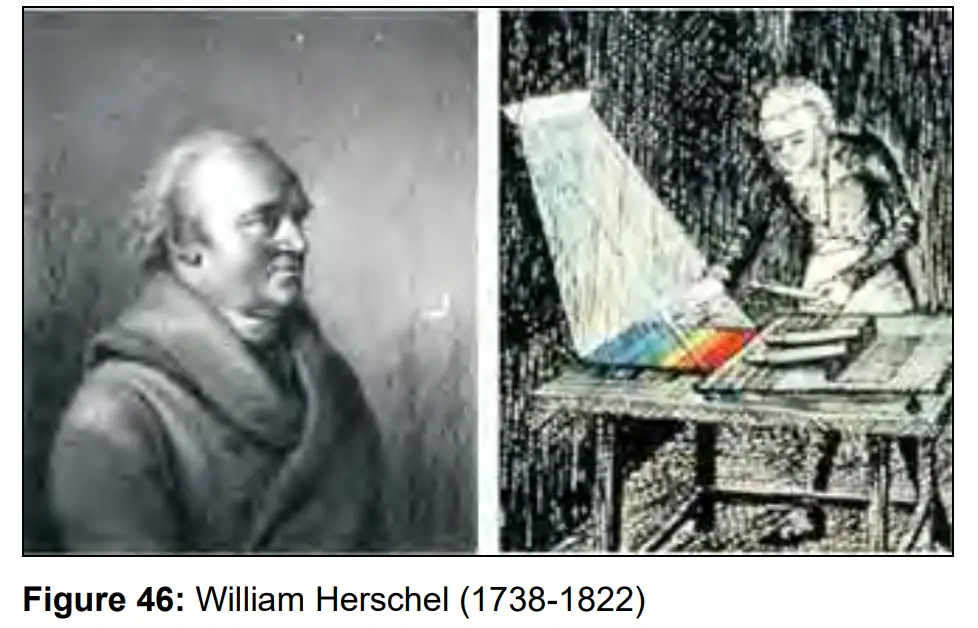
He blackened the peak of a sensitive mercury thermometer. This thermometer, a glass prism that led sun rays onto a table made his measuring arrangement. With this, he tested the heating of different colors of the spectrum. Slowly moving the peak of the blackened thermometer through the colors of the spectrum, he noticed the increasing temperature from violet to red. The temperature rose even more in the area behind the red end of the spectrum. Finally he found the maximum temperature far behind the red area.
Nowadays this area is called “infrared wavelength area”.
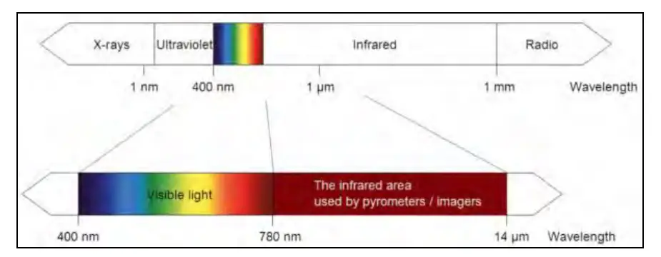 Figure 47: The electromagnetic spectrum and the area used for temperature measurement
For the measurement of “thermal radiation” infrared thermometry uses a wave-length ranging between 1 µm and 20 µm. The intensity of the emitted radiation depends on the material. This material contingent constant is described with the help of the emissivity which is a known value for most materials (►9 Emissivity).
Infrared thermometers are optoelectronic sensors. They calculate the surface temperature based on the emitted infrared radiation from an object. The most important feature of infrared thermometers is that they enable the user to measure objects contactless. Consequently, these products help to measure the temperature of inaccessible or moving objects without difficulties.
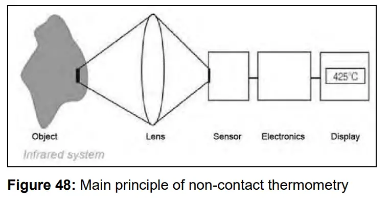
Infrared thermometers basically consist of the following components:
- Lens
- Spectral filter
- Detector
- Electronics (amplifier/ linearization/ signal processing)
The specifications of the lens decisively determine the optical path of the infrared thermometer, which is characterized by the ratio Distance to Spot size. The spectral filter selects the wavelength range, which is relevant for the temperature measurement. The detector in cooperation with the processing electronics transforms the emitted infrared radiation into electrical signals.
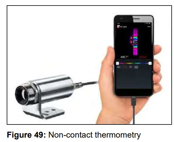
The advantages of non-contact thermometry are clear – it supports:
- temperature measurements of moving or overheated objects and of objects in hazardous surroundings
- very fast response and exposure times
- measurement without inter-reaction, no influence on the
- measuring object
- non-destructive measurement
- long lasting measurement, no mechanical wear

Application field:
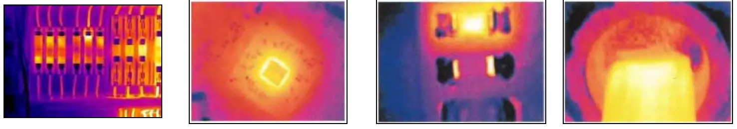 | |||
| Monitoring of electronic cabinets | R&D of electronics | R&D of electronic parts | Process control extruding plastic parts |
 | |||
| Process control manufacturing solar modules | Process control at calendering | R&D of mechanical parts | Monitoring of cables |
Emissivity
9.1 Definition
The intensity of infrared radiation, which is emitted by each body, depends on the temperature as well as on the radiation features of the surface material of the measuring object. The emissivity (ε – Epsilon) is used as a material constant factor to describe the ability of the body to emit infrared energy. It can range between 0 and 100 %. A “blackbody” is the ideal radiation source with an emissivity of 1.0 whereas a mirror shows an emissivity of 0.1.
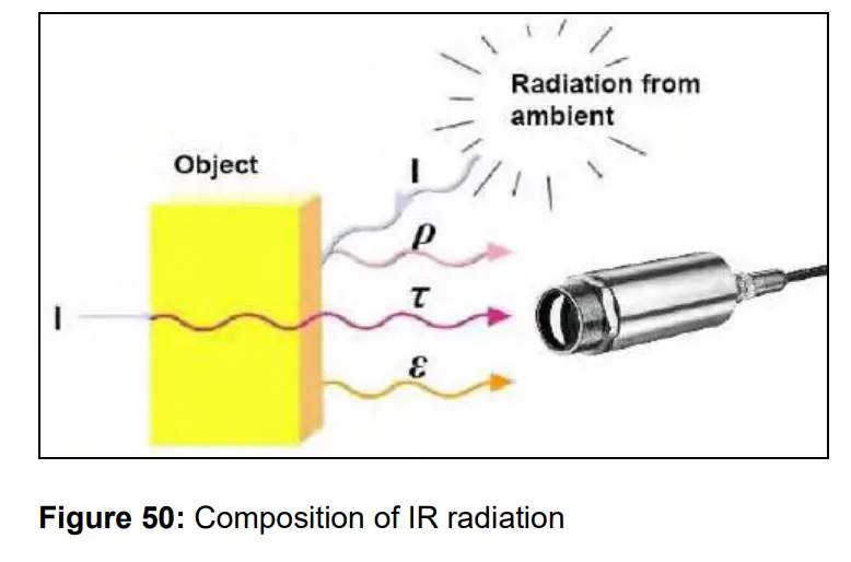
I IR radiation
ε Emission
ρ Reflection
τ Transmission
![]()
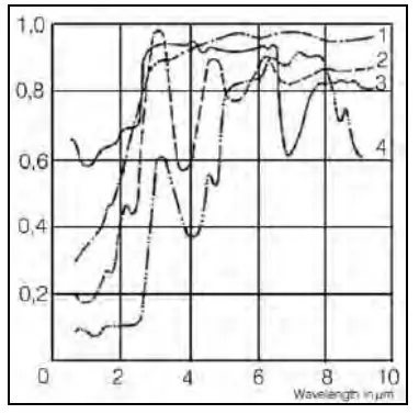 Figure 51: Spectral emissivity of several materials: 1 Enamel, 2 Plaster, 3 Concrete, 4 Chamotte
If the emissivity chosen is too high, the infrared thermometer may display a temperature value which is much lower than the real temperature – assuming the measuring object is warmer than its surroundings. A low emissivity (reflective surfaces) carries the risk of inaccurate measuring results by interfering infrared radiation emitted by background objects (flames, heating systems, chamottes). To minimize measuring errors in such cases, the handling should be performed very carefully, and the unit should be protected against reflecting radiation sources.
9.2 Determination of unknown emissivity
- First determine the actual temperature of the measuring object with a thermocouple or contact sensor. Second, measure the temperature with the infrared thermometer and modify the emissivity until the displayed result corresponds to the actual temperature.
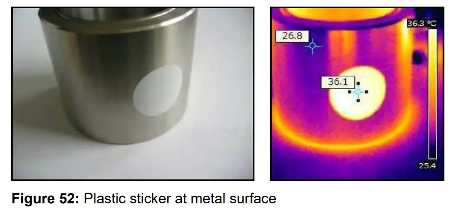
- If you monitor temperatures of up to 380 °C you may place a special plastic sticker (emissivity dots – Part No.: ACLSED) onto the measuring object, which covers it completely.
 Set the emissivity to 0.95 and take the temperature of the sticker. Afterwards, determine the temperature of the adjacent area on the measuring object and adjust the emissivity according to the value of the temperature of the sticker.
- Cove a part of the surface of the measuring object with a black, flat paint with an emissivity of 0.98. Adjust the emissivity of your infrared thermometer to 0.98 and take the temperature of the colored surface. Afterwards, determine the temperature of a directly adjacent area and modify the emissivity until the measured value corresponds to the temperature of the colored surface.
 CAUTION: On all three methods the object temperature must be different from ambient temperature.
 Set the emissivity to 0.95 and take the temperature of the sticker. Afterwards, determine the temperature of the adjacent area on the measuring object and adjust the emissivity according to the value of the temperature of the sticker.
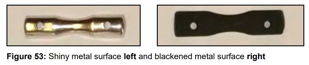 CAUTION: On all three methods the object temperature must be different from ambient temperature.
9.3 Characteristic emissivity
In case none of the methods mentioned above help to determine the emissivity you may use the emissivity table ► Appendix A and Appendix B.
These are average values, only. The actual emissivity of a material depends on the following factors:
- temperature
- measuring angle
- geometry of the surface
- thickness of the material
- constitution of the surface (polished, oxidized, rough, sandblast)
- spectral range of the measurement
- transmissivity (e.g. with thin films)
 Figure 54: Adjustment of the emissivity in the software PIX Connect (menu Tools/ Configuration/ Device)
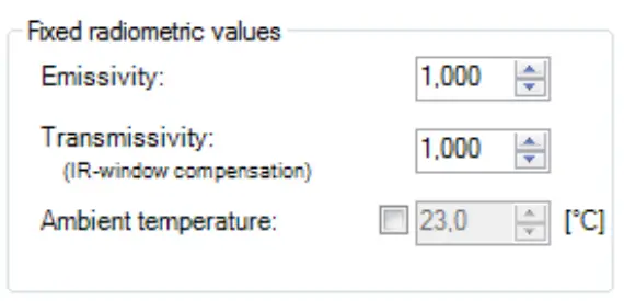 Figure 54: Adjustment of the emissivity in the software PIX Connect (menu Tools/ Configuration/ Device)
Appendix A – Table of emissivity for metals
| Material | typical Emissivity | ||||
| Spectral response | 1.0 pm | 1.6 pm | 5.1 pm | 8-14 pm I | |
| Aluminium | non oxidized | 0.1-0.2 | 0.02-0.2 | 0.02-0.2 | 0.02-0.1 |
| polished | 0.1-0.2 | 0.02-0.1 | 0.02-0.1 | 0.02-0.1 | |
| roughened | 0.2-0.8 | 0.2-0.6 | 0.1-0.4 | 0.1-0.3 | |
| oxidized | 0.4 | 0.4 | 0.2-0.4 | 0.2-0.4 | |
| Brass | polished | 0.35 | 0.01-0.05 | 0.01-0.05 | 0.01-0.05 |
| roughened | 0.65 | 0.4 | 0.3 | 0.3 | |
| oxidized | 0.6 | 0.6 | 0.5 | 0.5 | |
| Copper | polished | 0.05 | 0.03 | 0.03 | 0.03 |
| roughened | 0.05-0.2 | 0.05-0.2 | 0.05-0.15 | 0.05-0.1 | |
| oxidized | 0.2-0.8 | 0.2-0.9 | 0.5-0.8 | 0.4-0.8 | |
| Chrome | 0.4 | 0.4 | 0.03-0.3 | 0.02-0.2 | |
| Gold | 0.3 | 0.01-0.1 | 0.01-0.1 | 0.01-0.1 | |
| Haynes | alloy | 0.5-0.9 | 0.6-0.9 | 0.3-0.8 | 0.3-0.8 |
| Inconel | electro polished | 0.2-0.5 | 0.25 | 0.15 | 0.15 |
| sandblast | 0.3-0.4 | 0.3-0.6 | 0.3-0.6 | 0.3-0.6 | |
| oxidized | 0.4-0.9 | 0.6-0.9 | 0.6-0.9 | 0.7-0.95 | |
| Iron | non oxidized | 0.35 | 0.1-0.3 | 0.05-0.25 | 0.05-0.2 |
| rusted | 0.6-0.9 | 0.5-0.8 | 0.5-0.7 | ||
| oxidized | 0.7-0.9 | 0.5-0.9 | 0.6-0.9 | 0.5-0.9 | |
| forged, blunt | 0.9 | 0.9 | 0.9 | 0.9 | |
| molten | 0.35 | 0.4-0.6 | |||
| Iron. tasted | non oxidized | 0.35 | 0.3 | 0.25 | 0.2 |
| oxidized | 0.9 | 0.7-0.9 | 0.65-0.95 | 0.6-0.95 | |
| Material | typical Emissivity | ||||
| Spectral response | 1.0 pm | 1.6 pm | 5.1 pm | 8-14 pm | |
| Lead | polished | 0.35 | 0.05-0.2 | 0.05-0.2 | 0.05-0.1 |
| roughened | 0.65 | 0.6 | 0.4 | 0.4 | |
| oxidized | 0.3-0.7 | 0.2-0.7 | 0.2-0.6 | ||
| Magnesium | 0.3-0.8 | 0.05-0.3 | 0.03-0.15 | 0.02-0.1 | |
| Mercury | 0.05-0.15 | 0.05-0.15 | 0.05-0.15 | ||
| Molybdenum | non oxidized | 0.25-0.35 | 0.1-0.3 | 0.1-0.15 | 0.1 |
| oxidized | 0.5-0.9 | 0.4-0.9 | 0.3-0.7 | 0.2-0.6 | |
| Monel (Ni-Cu} | 0.3 | 0.2-0.6 | 0.1-0.5 | 0.1-0.14 | |
| Nickel | electrolytic | 0.2-0.4 | 0.1-0.3 | 0.1-0.15 | 0.05-0.15 |
| oxidized | 0.8-0.9 | 0.4-0.7 | 0.3-0.6 | 0.2-0.5 | |
| Platinum | black | 0.95 | 0.9 | 0.9 | |
| Silver | 0.04 | 0.02 | 0.02 | 0.02 | |
| Steel | polished plate | 0.35 | 0.25 | 0.1 | 0.1 |
| rustless | 0.35 | 0.2-0.9 | 0.15-0.8 | 0.1-0.8 | |
| heavy plate | 0.5-0.7 | 0.4-0.6 | |||
| cold-rolled | 0.8-0.9 | 0.8-0.9 | 0.8-0.9 | 0.7-0.9 | |
| oxidized | 0.8-0.9 | 0.8-0.9 | 0.7-0.9 | 0.7-0.9 | |
| Tin | non oxidized | 0.25 | 0.1-0.3 | 0.05 | 0.05 |
| Titanium | polished | 0.5-0.75 | 0.3-0.5 | 0.1-0.3 | 0.05-0.2 |
| oxidized | 0.6-0.8 | 0.5-0.7 | 0.5-0.6 | ||
| Wolfram | polished | 0.35-0.4 | 0.1-0.3 | 0.05-0.25 | 0.03-0.1 |
| Zinc | polished | 0.5 | 0.05 | 0.03 | 0.02 |
| oxidized | 0.6 | 0.15 | 0.1 | 0.1 | |
Appendix B – Table of emissivity for non-metals
| Material | typical Emissivity | ||||
| Spectral response | 1.0 pm | 2.2 pm | 5.1 pm | 3-14 pm | |
| 4,stestcs | 0.9 | 0.8 | 0.9 | 0.95 | |
| Asphalt | 0.55 | 0.95 | |||
| Basalt | 0.7 | 0.7 | |||
| Carbon | non oxidized graphite | 0.8-0.9 0.8-0.9 | 0.3-0.9 0.7-0.9 | 08-0.9 0.7-0.8 | |
| Carborundum | 0.95 | 0.9 | 0.9 | ||
| Ceramic | 0.4 | 0.8-0.95- | 0.8-0.95 | 0.95 | |
| Concrete | 0.65 | 0.9 | 0.9 | 0.95 | |
| Glass | plate melt | 0.2 0.4-0.9 | 0.93 0.5 | 0.85 | |
| Grit | 0.95 | 0.95 | |||
| Gypsum | 0.4-0.97 | 0.8-0.95 | |||
| Ice | 0.93 | ||||
| Limestone | 0.4-0.98 | 0.93 | |||
| Paint | non alkaline | 0.9-0.95 | |||
| Paper | any color | 0.95 | 0.95 | ||
| Plastic >50 μm | non transparent | 0.95 | 0.95 | ||
| Rubber | 0.9 | 0.95 | |||
| Sand | 0.9 | 0.9 | |||
| Snow | 0.9 | ||||
| Soil | 0.9-0.98 | ||||
| Textiles | 0.95 | 0.95 | |||
| Water | 0.93 | ||||
| Wood | natural | _ :lc | 0.9-0.95 | ||
Appendix C – Quick start for serial communication
Introduction
One special feature of the PIX Connect software contains the possibility to communicate via a serial COMPort interface. This can be a physical COM-Port or a virtual COM-Port (VCP). It must be available on the computer where the PIX connect software is installed.
Setup of the interface
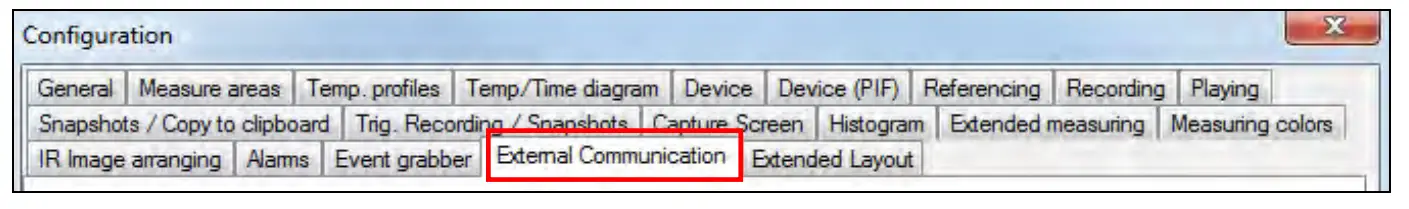
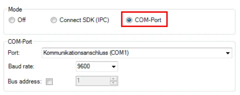
- Open the Options dialog and enter the tab “Extended Communication” to enable the software for the serial communication.

- Select the mode “COM-Port” and choose the appropriate port.

- Select the baud rate that matches the baud rate of the other communication device. The other interface parameters are 8 data bits, no parity and one stop bit (8N1).
These parameters are used in many other communication devices too. The other station must support 8 bit data. - Connect the computer with the communication device. If this is a computer too, use a null modem cable.
Command list![]() The command list is provided on the USB stick and in the PIX Connect software (Help → SDK). Every command must expire with CR/LF (0x0D, 0x0A).
The command list is provided on the USB stick and in the PIX Connect software (Help → SDK). Every command must expire with CR/LF (0x0D, 0x0A).
RS485 for Xi 80 and Xi 410
The Xi 80 and Xi 410 cameras support a direct RS485 connection. RS485 interface is designed for highspeed serial data transmission over long distances and as a bidirectional bus system with up to 32 participants. An RS485 bus can be set up as a 2-wire as well as a 4-wire system. For the Xi 80/410 cameras, it is designed for a 2-wire system. A maximum cable length of 500 meters can be realized. At least a master and slave is necessary for communication. The master can be a PLC system and the slave is the camera.
RS485 is supported for Xi 80 cameras which have the hardware version 3001, firmware 3023 and at least the serial number which starts with 1812xxxx. For the Xi 410 it is working for all cameras starting at firmware version 3815. Here it is important that the communication is just working via Ethernet connection or in autonomous mode, but not with USB.
The connection for RS485 can be done directly on the terminal block (A and B) which is provided in the scope of supply of the camera.
Command list![]() The command list and more information can be found on the supplied USB stick under Documentation and Manuals (Serial Communication Description-RS485-xxxx-xx-x). Every command must expire with CR/LF (0x0D, 0x0A).
The command list and more information can be found on the supplied USB stick under Documentation and Manuals (Serial Communication Description-RS485-xxxx-xx-x). Every command must expire with CR/LF (0x0D, 0x0A).
Appendix D – Interprocess Communication (IPC)
![]() The description of the initialization procedure as well as the necessary command list is provided on the USB stick and in the PIX Connect software (Help → SDK).
The description of the initialization procedure as well as the necessary command list is provided on the USB stick and in the PIX Connect software (Help → SDK).
2 SDK packages are available (included on USB stick):
- Connect SDK: requires the PIX Connect software
- Direct SDK: no PIX Connect software required, supports Linux and Windows
The communication to the process imager device is handled by the PIX Connect software (Imager.exe) only. A dynamic link library (ImagerIPC2.dll) provides the interprocess communication (IPC) for other attached processes. The DLL can be dynamically linked into the secondary application. Or it can be done static by a lib file too. Both Imager.exe and ImagerIPC2.dll are designed for Windows 7/ 8/ 10 only. The application must support call-back functions and polling mode.
The ImagerIPC2.dll will export a bunch of functions that are responsible for initiating the communication, retrieving data and setting some control parameters.
The main difference to the former Version 1 (ImagerIPC.dll) is the support of more than one Optris Xi via multiple instances of Optris PIX Connect.
Appendix E – PIX Connect Resource Translator
A detailed tutorial is provided on the USB stick.
PIX Connect is a .Net Application. Therefore, it is ready for localization. Localization as a Microsoft idiom means a complete adaption of resources to a given culture. Learn more about the internationalization topics consult Microsoft’s developer documentation on
http://msdn.microsoft.com/en-us/goglobal/bb688096.aspx.
If desired the localization process can be illustrated in detail. Also, the resizing of buttons or other visible resources and the support of right-to-left-languages are supported. Experts who have the appropriate tools should handle it. Nevertheless, we have developed the small tool “Resource Translator” to make the translation of the resources of the PIX Connect application possible for everybody.
This tool helps to translate any visible text within the PIX Connect application.
Appendix F – Wiring diagrams PIF for Xi 400
Analog Output:
The maximum load impedance is 500 Ohm.
The analog output can be used as a digital output too. The current value for “no alarm” and “alarm on” is set within the software.
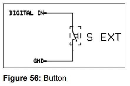
Digital Input:
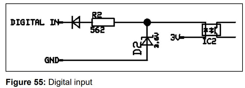
The digital input can be activated with a button to the Xi GND-Pin or with a low level CMOS/TTL signal: Low level 0…0.6 V; High level 2…24 V
Example Button:
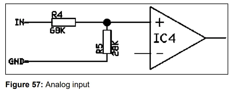
Analog input (usable voltage range: 0 … 10 V):
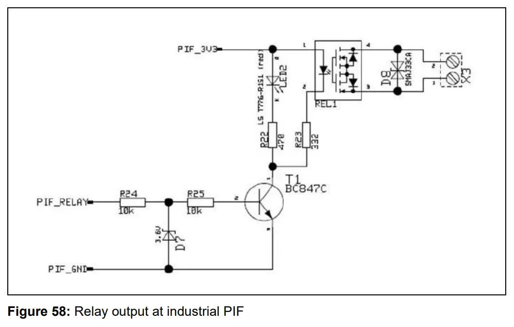
Relay output at industrial PIF [Part No.: ACPIPIFMACBxx]
The analog output must be set to “Alarm”. The range for AO1-AO3 can be set in the software (no alarm: 0-4 mA/ alarm:
10-20 mA).
REL1-3 (DO1-DO3):
Umax = 30 VDC
Imax = 400 mA
Appendix G – Declaration of Conformity
![]() 1.888.610.7664
1.888.610.7664![]() www.calcert.com
www.calcert.com
[email protected]
References
 System.Globalization Namespace | Microsoft Learn
-
Calcert
 Assembly of Xi 400 into the water cooling housing with the use of the laminar air purge
-
Mounting the laminar air purge attachment on Xi 80 with mounting bracket
-
Optics calculator for infrared cameras
-
optris PIX Connect for download
-
Replacement of the Si-protective window of the laminar air purge attachment


