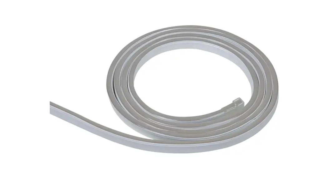
![]() L372D40 Flex Tube Flat Digital RGBW
L372D40 Flex Tube Flat Digital RGBW
User Manual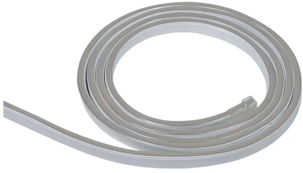
FLEX TUBE FLAT DIGITAL RGBW
USER MANUAL
MBN GmbH, Balthasar-Schaller-Str. 3, 86316 Friedberg – Germany www.proled.com
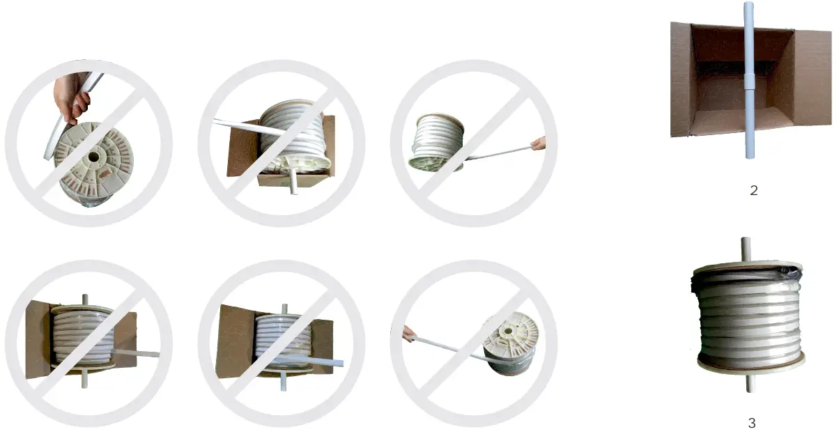
Unpacking
Reel Packaging 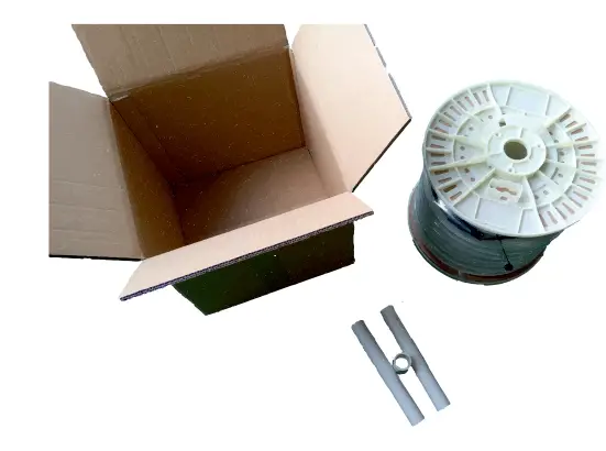
Box Packaging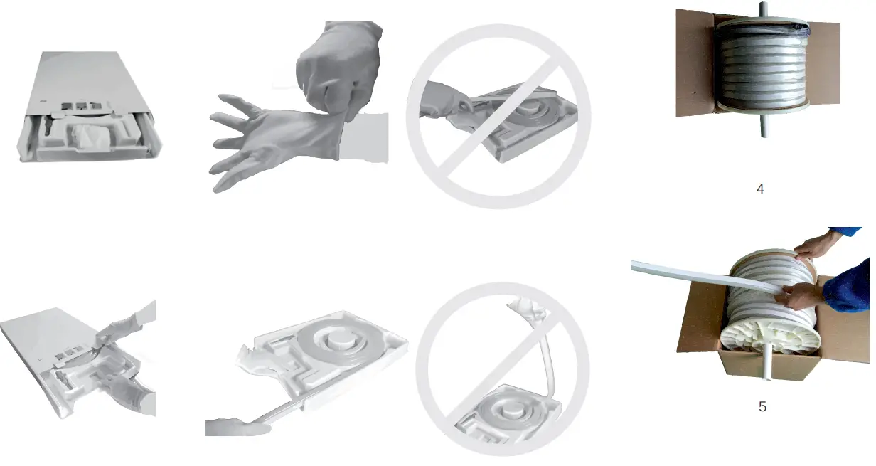
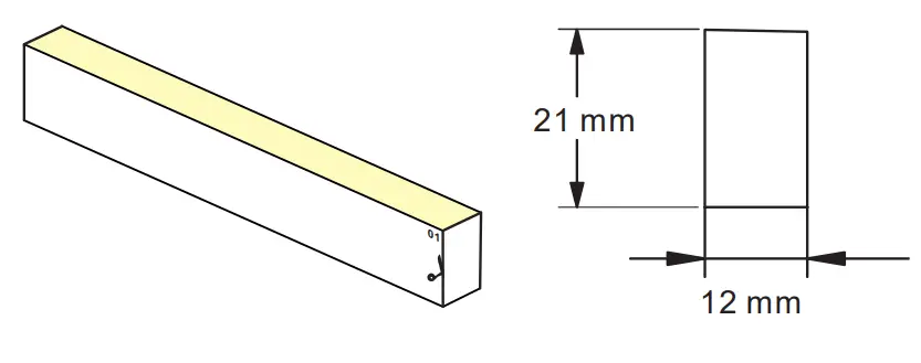
Technical Data
- Dimensions 12 x 21mm
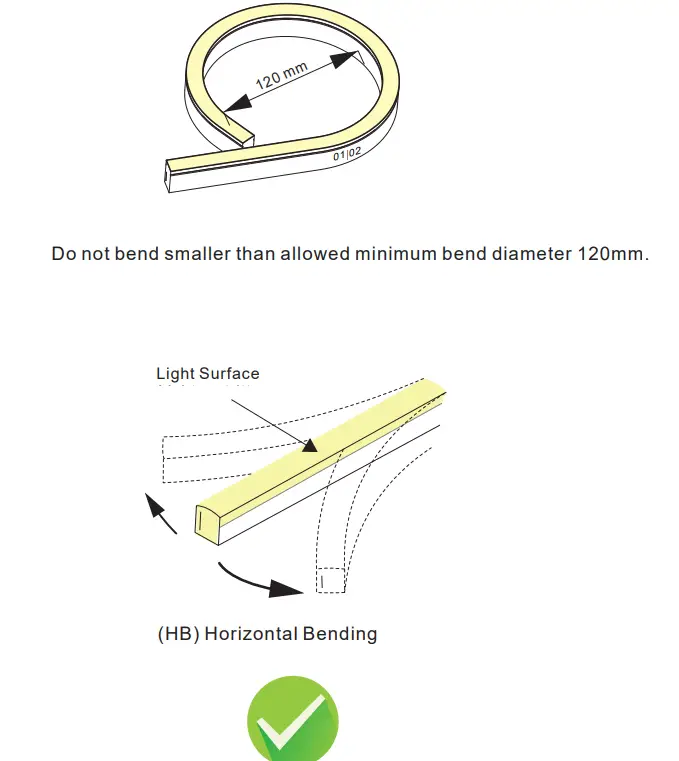
- Min. bend diameter 120 mm
- Protection rate IP67
- The product IP rate is ultimately in line with properly applied IP-rated connectors.
- Working ambient temperature -20°C – 45°C.
- Environmental Installation Temperature 0°C – 45°C.
- This product contains a light source of Energy class G.
- The light source in the containing product can not be replaced.

Note
Max. length per power input: Indoor (constant temperature) single end max. 10 m, double end max. 20 m. Outdoor (because of temperature fluctuations and different thermal expansion coefficients of the materials) max. 7m
| Light color | Cuttable all | LEDs per segment | LED power |
| RGBW | 12,5 cm | 7 | 15 W/m |
Cautions
- Before making any cuts, installation, maintenance, or connection, be sure the mains is disconnected!
- Note: all connector joints must be connected correctly to achieve an IP67 rating.
- Please operate this flex light by instructions, and confirm the working voltage, it must match with product requirements.
- Please confirm the polarity of the connector before insertion the front connection cable.

- Connect and cut this product correctly. Any wrong operation will damage this product.
- Use a qualified DC power supply.
- Please use and bend this flex tube correctly. See the figures on the right.
- Do not operate the light when the ambient temperature exceeds the range of specified temperature in the User Manual.
- Do not energize the light over 30 minutes in coil packaging.
Cutting instructions
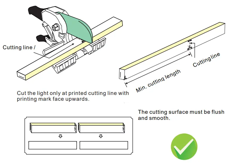
Note:
- Place the tube horizontally when cutting it.
- Use only factory-recommended cutter.
- Cut the tube according to the following instructions.
The incorrect operation will damage the tube.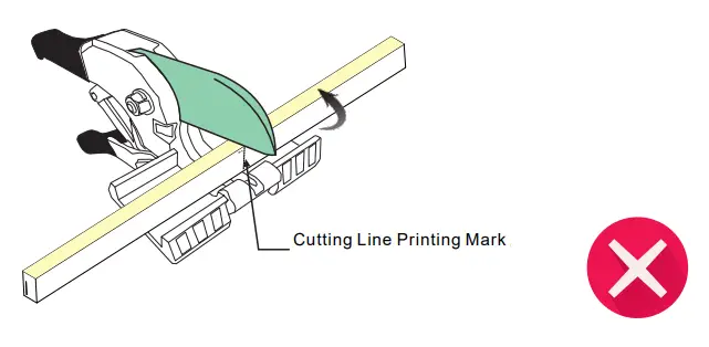 The printing mark should be faced upwards.
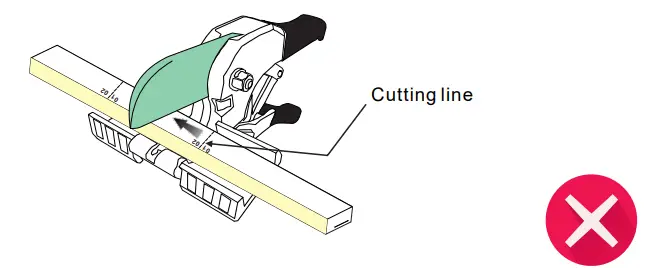
Cutting can only be made at the printed cutting line. 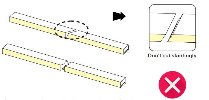 Cutting can only be made at the printed cutting line.
WARNING: The above mishandling will damage the tube
IP67 connector
Please ignore these steps, if the front connector has been assembled before delivery.
Note: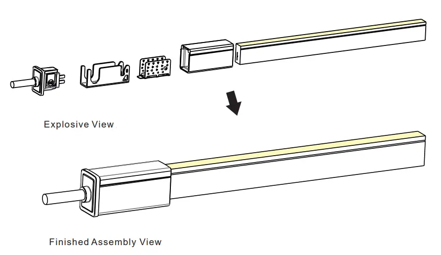
- Never wet the assembly units or assemble them with wet hands.
- Please use the tools correctly.
- Please pay attention to personal security when using tools.
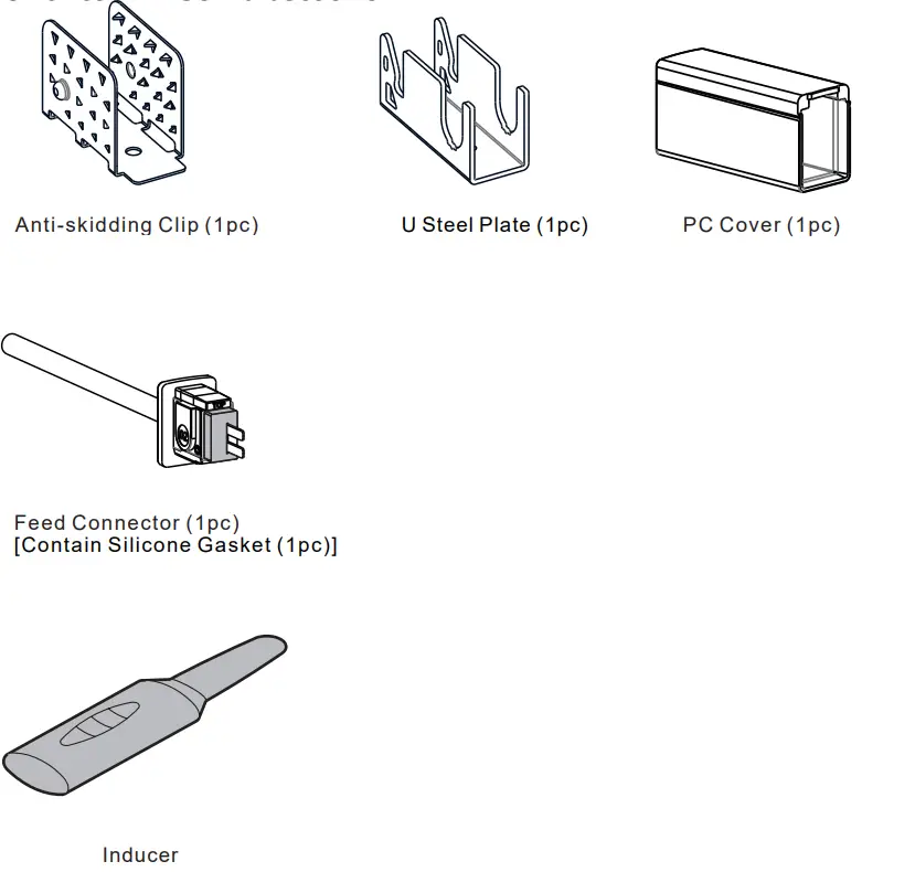
1. Components of Front Connector
Note:
The tube ends are marked with either an 01 or an 02. Always make sure to use an identically labeled connector for the appropriate direction.
2. Tools
 3. Installation Steps
3.1 Placing PC Cover
Pay attention to the direction marked on the bottom of the PC cover. 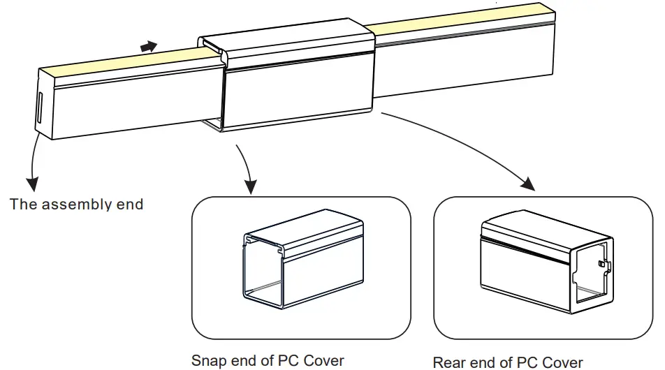
3.2 Inducing a Cavity for Feed Connector
NEVER insert into the front side (LED side) of the PCB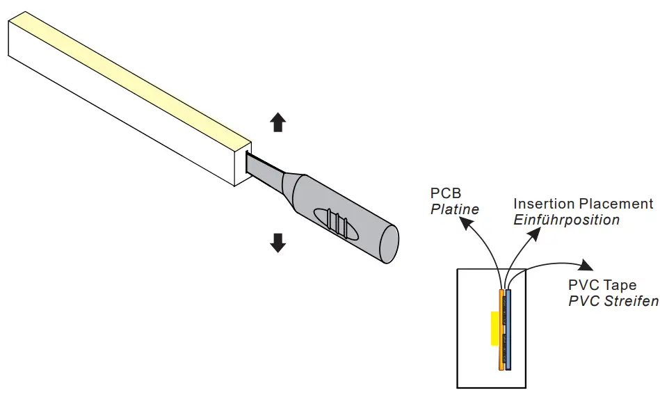 Insert the inducer to the backside of the PCB around 10~12mm, and move the inducer up and down 3~5 times gently to create a small cavity.
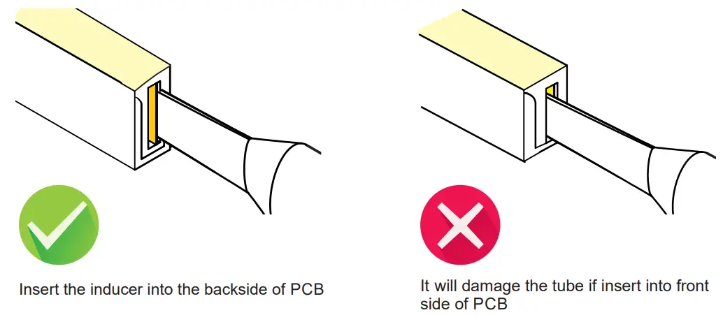
3.3 Inserting the Feed Connector 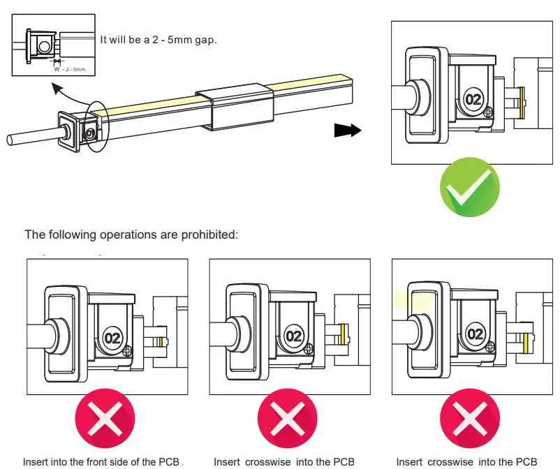 3.4 Treatment of Anti-skidding Clip
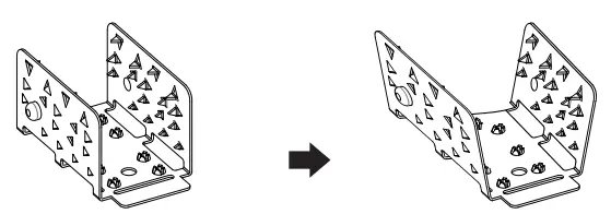
Unfold the anti-skidding clip about 20 degrees on both sides.
3.5 Installation of Anti-Skidding Clip
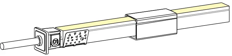
Place the anti-skidding clip onto the assembly end of the light. Pay attention to its direction. 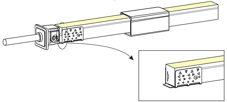 Fit the anti-skidding clip to the end of the light so that it wraps tightly and its brim is aligned with the cut edge on both sides.
3.6 Installation of U Steel Plate and PC Cover 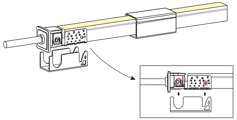
Align the feed connector and antiskidding clip with the U steel plate.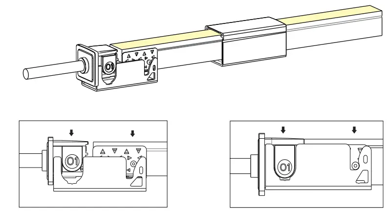 Press the feed connector and tube downwards at the same time till the bottom.
Please energize the tube to check its functionality and do waterproof reliability testing after connector assembly.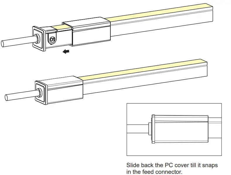
IP67 End cap
Please ignore these steps, if the End Cap has been assembled before delivery.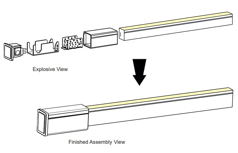
1. Components of End Cap
2. Tools 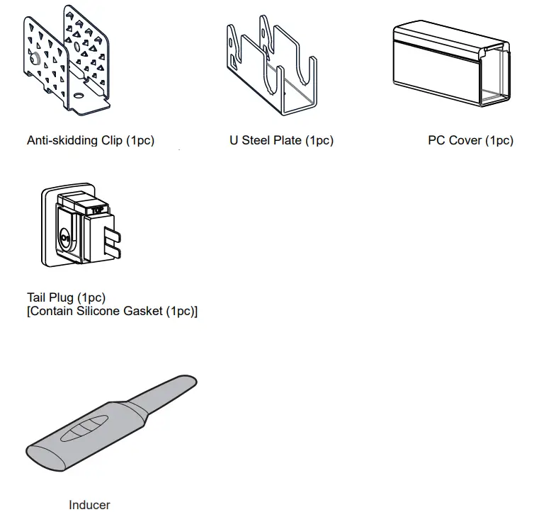
3. Installation Steps
Pay attention to the direction marked on the bottom of PC cover. 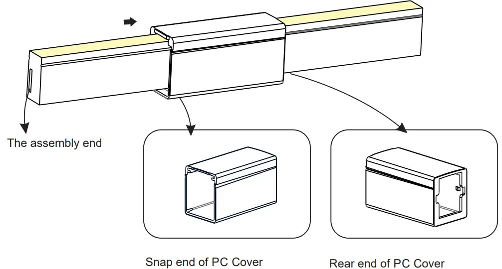
3.2 Inducing a Cavity for Feed Connector
NEVER insert into the front side (LED side) of the PCB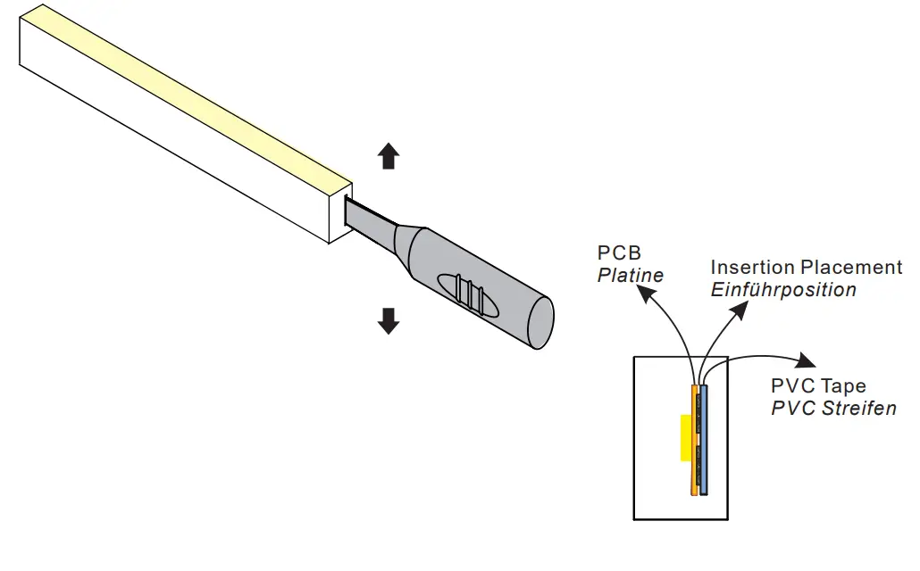
Insert the inducer to the backside of PCB around 10~12mm, move the inducer up and down 3~5 times gently to create a small cavity.
3.3 Inserting the Feed Connector 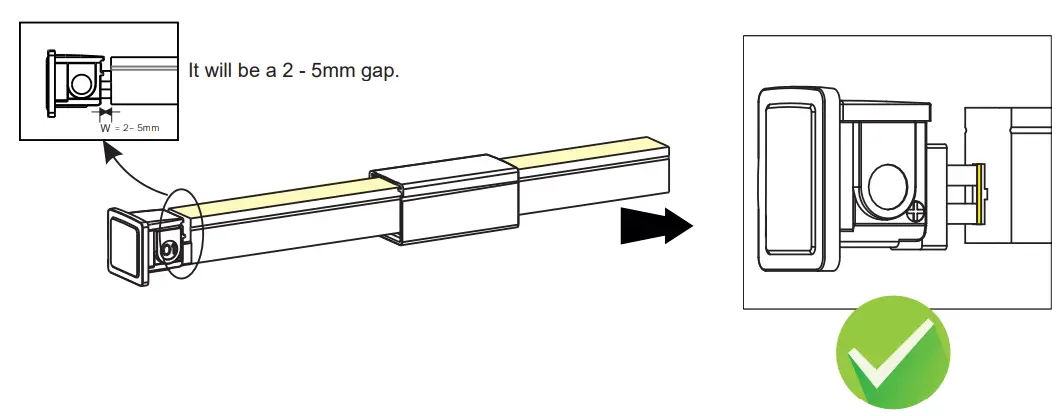
The following operations are prohibited: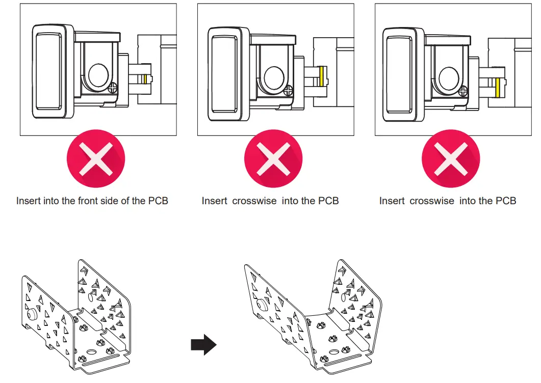
3.4 Treatment of Anti-skidding Clip
Unfold the anti-skidding clip about 20
3.5 Installation of Anti-Skidding Clip
 Place the anti-skidding clip onto the assembly end of the light. Pay attention to its direction.
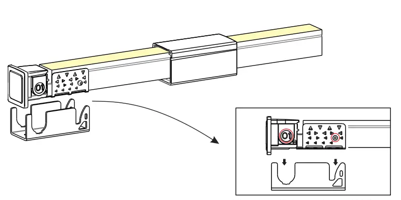 Fit the anti-skidding clip to the end of the light so that it wraps tightly and its brim is aligned with the cut edge on both sides.
3.6 Installation of U Steel Plate and PC Cover
Please energize the tube to check its functionality and do waterproof reliability testing after connector assembly.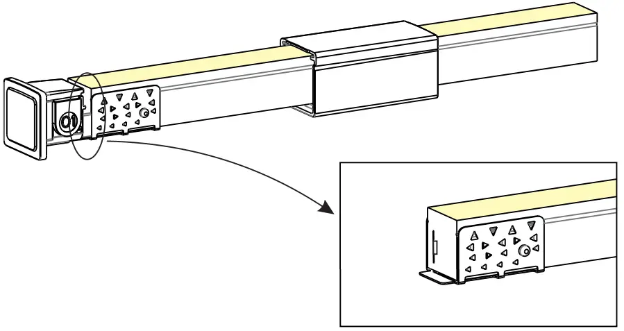 Align the feed connector and antiskidding clip with the U steel plate.
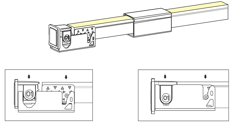 Press the feed connector and tube downwards at the same time till the bottom.
 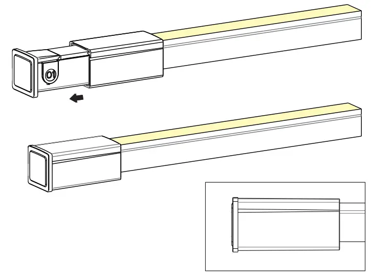 Slide back the PC cover till it snaps in the feed connector.
Diagram of Tube Wiring
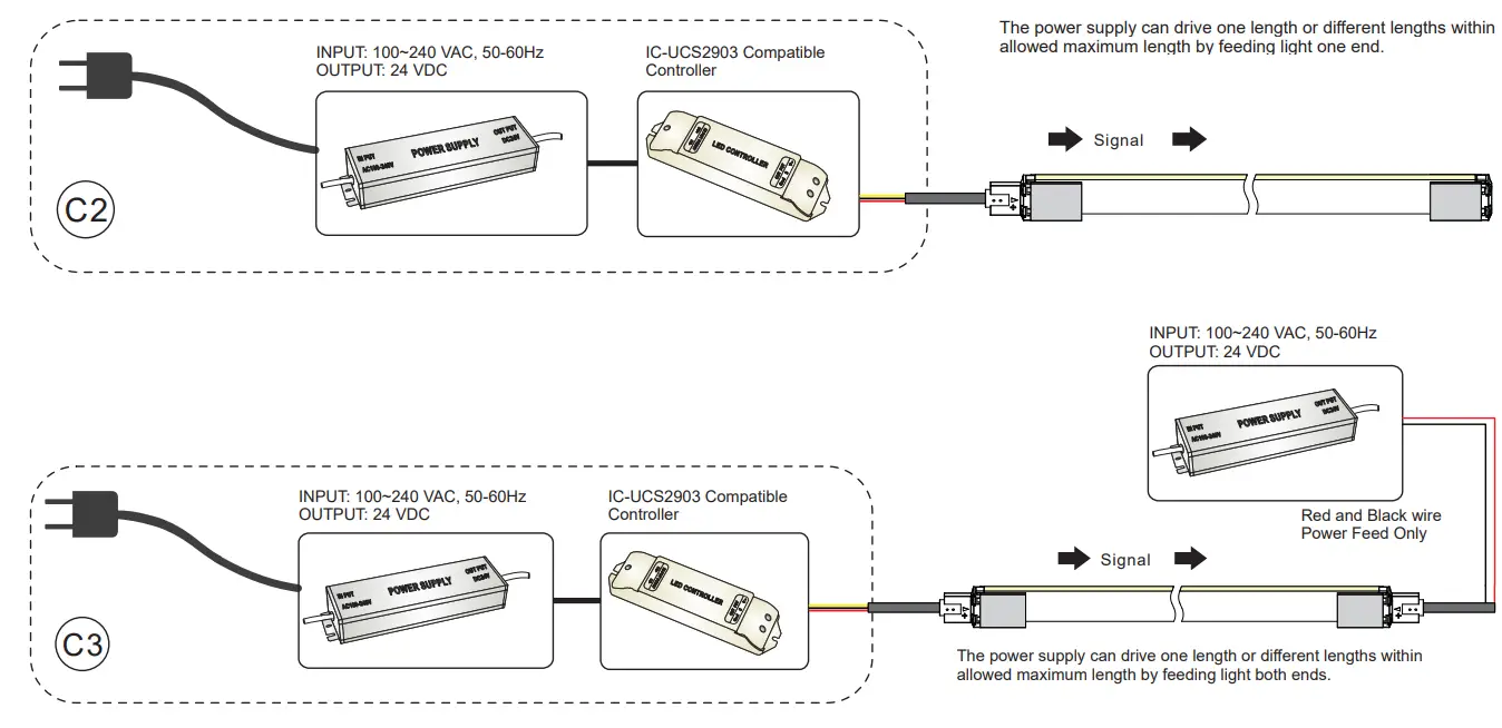
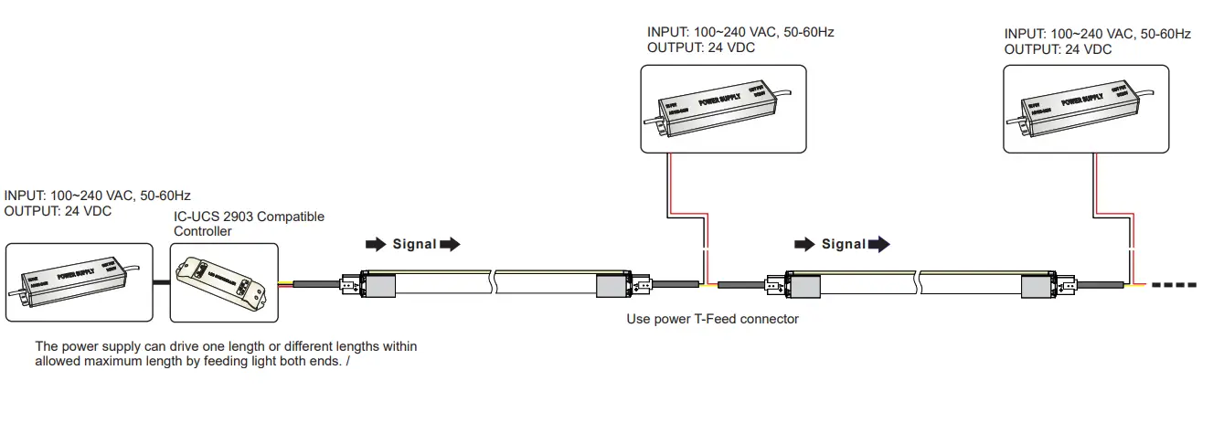
1. Digital RGBW Tube Wiring / Anschlußdiagramm für Digital RGBW Tubes
Note:
- This Flex Tube must be used in conjunction with 24 VDC power supply
- Always observe proper polarity
- Ensure to add 20% buffer when sizing the power supply
- Ensure that the power cable carried current is no greater than 80% of its capacity
- To minimize voltage drop and keep light consistency, position the power supply nearest to the power feed end of the Flex Tube and keep the power line as short as possible.
Instructions for Digital RGBW Tube Wiring:
Red Wire Connects to the“VCC” or Anode(+) Terminal
Yellow Wire Connects to the “Signal” Terminal.
Black Wire Connects to the“GND”or Cathode(-) Terminal
Anleitung für Digital RGBW Tube Anschluß:
Rote Leitung an “VCC”oder Anode(+) anklemmen
Note
The Digital RGBW Tube allows direct control of every cutting section. To ensure IC chips receive strong control signals, please take care of the below-listed parameters:
- To ensure a strong signal the 3-wire signal cable should not exceed 10 m.
- For cable lengths more than 10 m, a signal amplifier must be used.
Note
Max. length per power input: Indoor (constant temperature) single end max. 10 m, double end max. 20 m.
Outdoor (because of temperature fluctuations and different thermal expansion coefficients of the materials) max. 7m
Mounting Profiles
1. Self-locking Aluminum Profile with clip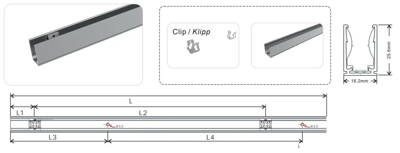
Dimensions
| Model | W x H(mm) B x H (mm | Length(mm) | L1(mm) | L2(mm) | L3(mm) | L4(mm) | Screw Hole(mm) | Hole Number | Clip Number |
| L372A17 | 16.2×25.6 | 2000 | 25 | 243.8 | 100 | 200 | Ø 3.5 | 10 | 9 |
2. Installation Guide 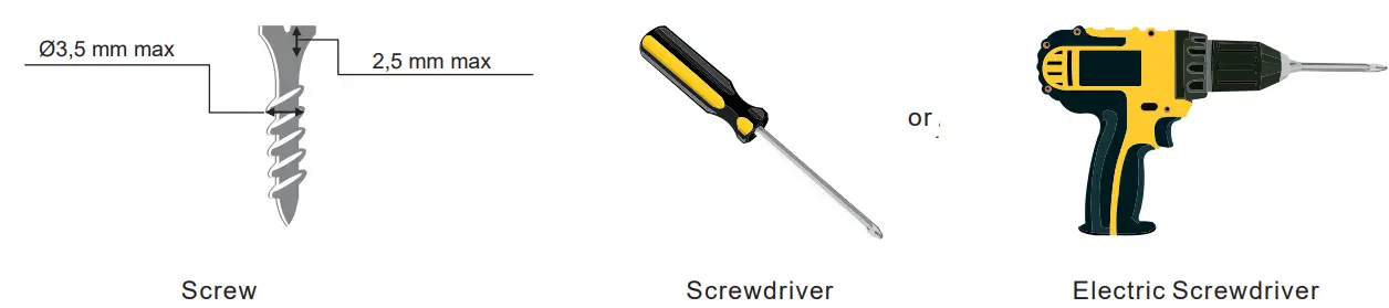
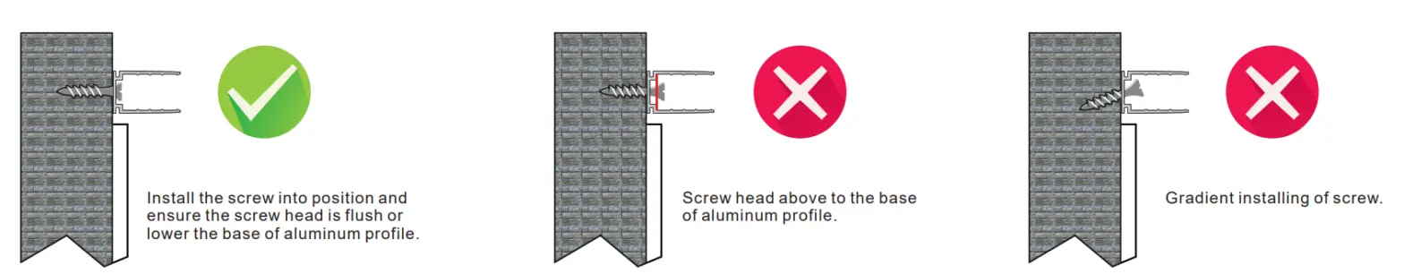
2.2 Correct Installation of Standard Aluminum Profile 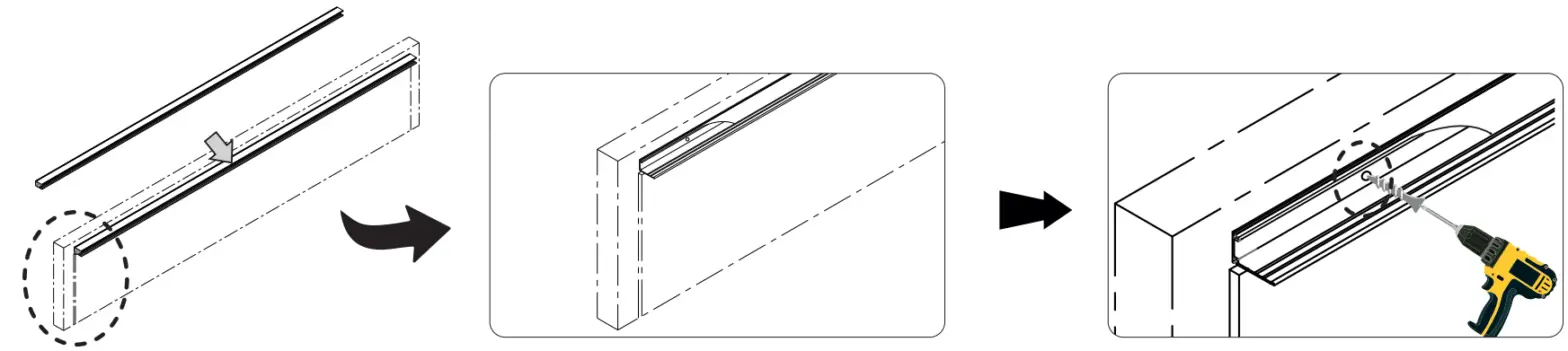
3. Requirements and Cautions for Installation of Mounting Profile
3.1 For Tubes with IP67 connectors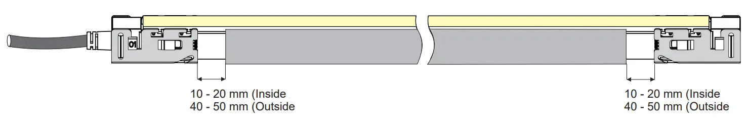 Ensure the supply cord is not subject to mechanical stress.
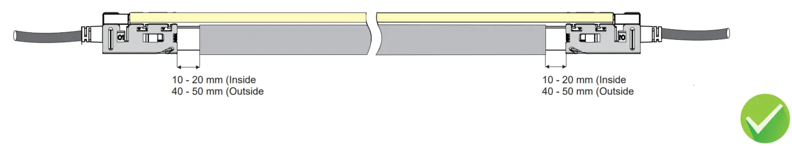 Mechanical stress on the front connector cable shall be avoided.
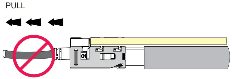 It is forbidden to curl or pull the front connector cable with force.
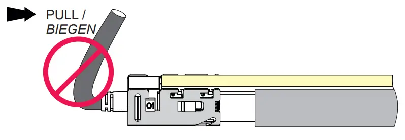 It is forbidden to let any connector aluminum mounting piece on the aluminum profile and make tube deformation.
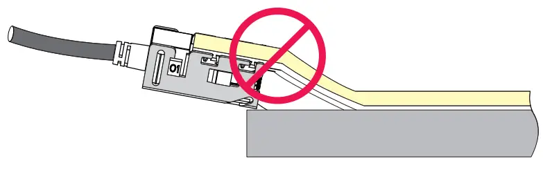 A to small space between the aluminum profile and the aluminum mounting piece is forbidden.
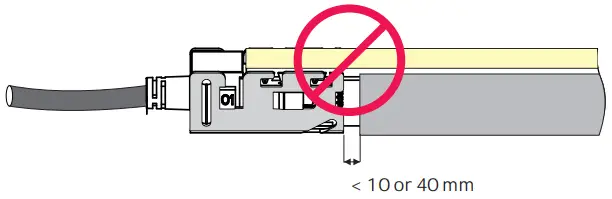 Install tube in one direction. Don’t let it choke anywhere.
4.3 Bending in the Process of Installation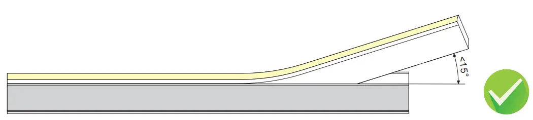
Installing angle should be less than 15 degree when pressing the tube to the aluminum profile by hand.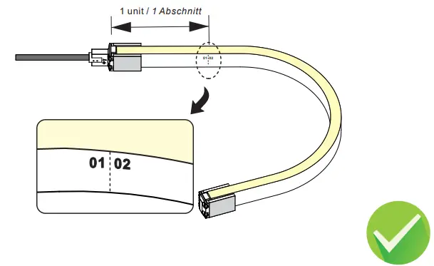
Please avoid bending at the first unit of the tube.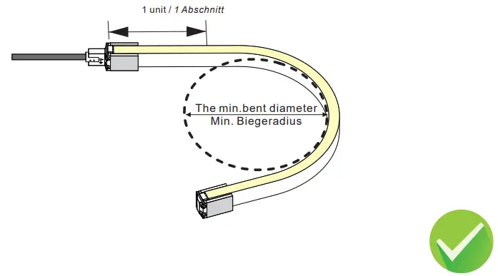 The tube can bend in a defined min. bending diameter or larger.
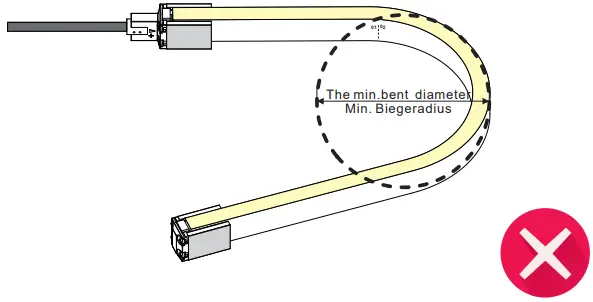
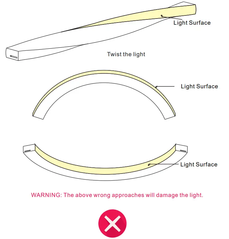
The circuit board and LEDs could be damaged, if the bending diameter is tighter than the defined min. bending diameter.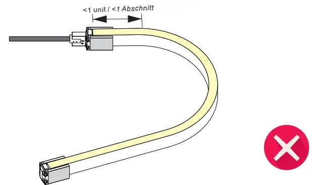 Do not bend against the first or last unit of the tube otherwise, it will lead to the failure of the connector waterproof.
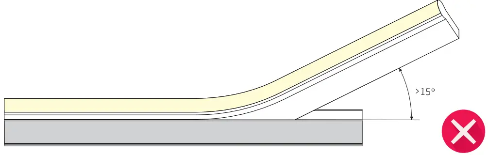
The circuit board could be damaged if installing an angle larger than 15 degrees.
Troubleshooting
The whole tube doesn’t work.
Check power supply is plugged in, switched on, and receiving power.
Check all tube, dimmer or controller connections, and connection from the power supply to the flex tube.
Check the polarity of all wire connections.
Make sure the power supply output voltage is 24V DC.
Check front connector is inserted into the backside of the PCB and properly assembled.
Light emitting appears dim or dull at one end.
Check whether the output voltage of the power supply is lower than that of the tube.
Adjust the dimming level to the maximum.
Power from both ends or shorten tube length to prevent voltage drop.
Light emitting appears excessive brightness.
Check whether the output voltage of the power supply is higher than that of the tube.
Check whether the power grid is stable.
If the first segment doesn’t work.
Cut not in indicated cutting line or not in a straight line. Cut out and remove the first segment.
Damage was caused to the first LED when inserting the front connector to the right side of the PCB. Cut out the first segment and properly assemble the connector.
Water ingress due to poor connector assembly could cause a short circuit of the first segment. Replace the length with a new one.
External impact damage inside LEDs. Only use your hands to install the flex tube into the aluminum profile.
The flex tube is flashing on and off.
Check the power supply to ensure it supports the length you are using. Select the appropriate strength or install an
additional power supply to support your installation.
Check power supply output voltage is stable.
Check front connector is properly installed with good contact with the copper PCB.
Check proper controller is connected for the tube to work.![]()


