Tronics-EVB3 Development Boards
Key Features of Tronics-EVB3
- Printed Circuit Board for evaluation of GYPRO® and AXO® products
- Includes 1 inertial sensor and external passive components
- Plug and Play SPI interface, compatible with Arduino Leonardo and Yùn
- RS422 and USB interfaces for Arduino boards
- 5V single power supply
- 5V, 3.3V and 1.8V compatibility for communication interface
General Description
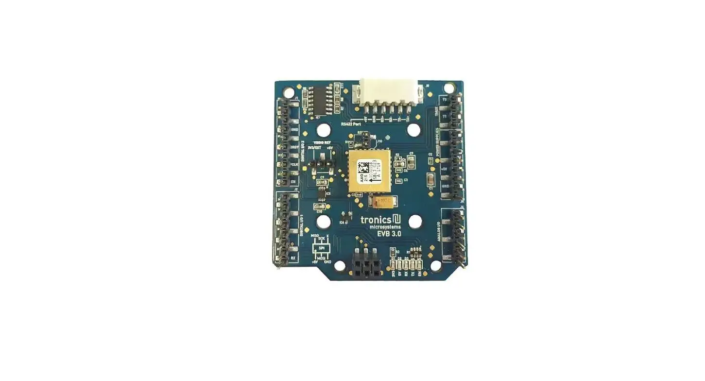
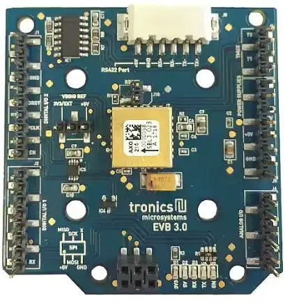
Tronics-EVB3 evaluation board is intended to perform characterizations of GYPRO4300 and AXO315 easily and quickly. Tronics-EVB3 was specially designed to be interfaced with an Arduino Leonardo or Arduino Yùn boards. The combination of Tronics-EVB3 with the Arduino platform is ideally suited for tests with rate table over the temperature range [-40°C to +85°C]. The 1.8V, 3.3V and 5V compatibility for SPI communication also enables connecting the Tronics-EVB3 with most of the acquisition systems and microcontrollers in the market. This document describes the mechanical and electrical features of the Tronics-EVB3 board as well as the SPI protocol used for the digital communication. This document is applicable to the whole AXO product line, including AXO315 accelerometers, and GYPRO4300 gyros. For more information about the performances of each product, please refer to the dedicated datasheet, available on our website.
Mechanical features
The evaluation board has the following dimensions:
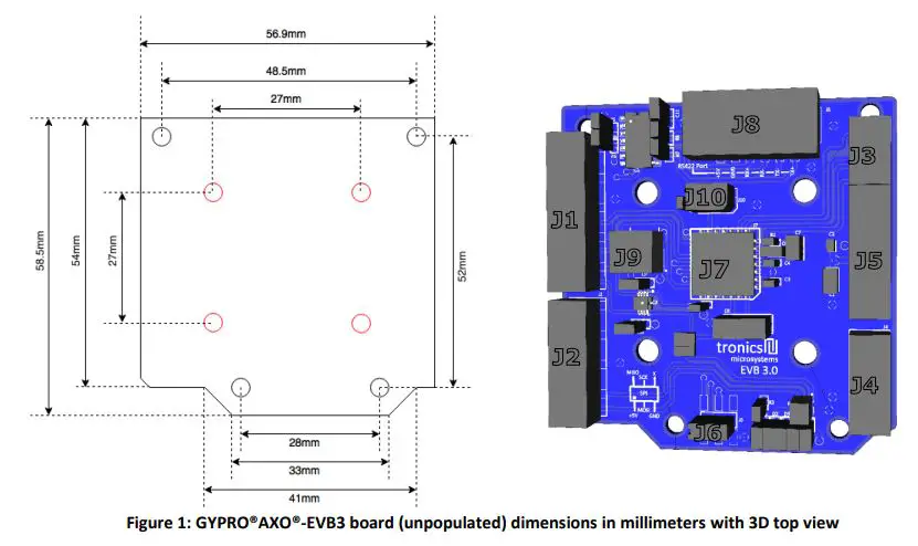
The main GYPRO®AXO®-EVB3 components are described in the table 1:
| Name | Description | Information |
| J1 | I/O connector | Tronics-EVB3 I/O signals : Enable pin: EN / Self-Test pin: ST / SPI Slave select: SSB / Data Ready pin: DRDY |
| J2 | I/O connector | Arduino UART signals (RX and TX) |
| J3 | I/O connector | Tronics reserved |
| J4 | I/O connector | Not used |
| J5 | I/O connector | Power supply: 5V, VDDIO, GND |
| J6 | I/O connector | Power supply lines: 5V, GND / SPI lines: MOSI, MISO, SCLK |
| J7 | GYPRO® or AXO® Product | Tronics inertial sensor |
| J8 | I/O connector | RS422 connector (RX+, RX-, TX+, TX-, GND) |
| J9 | I/O connector | SPI level voltage reference: With jumper on +5V : SPI level = +5V With jumper on 3V3/EXT : SPI level = VDDIO |
| J10 | I/O connector | Sensor reset: Without jumper: no reset / With jumper: reset |
Please note that the PCB has a flat backside and thickness of 1.6 mm. The board has been designed for a direct mounting onto the surface of your test equipment (rate table, vibration shaker…) in order to avoid parasitic mechanical resonance of the PCB.
Pins configuration and description
To enable compatibility with the Arduino platform, some signals are redundant, such as 5V and GND signals. If you don’t intend to use the Arduino platform, redundancy is not necessary. However, the pins marked with bold characters in the tables below must absolutely be connected.
- J1 gives access to the following signals:
Pin # Name Type Function #1 – – Not Connected #2 – – Not Connected #3 – – Not Connected #4 GND Power Ground Power Supply #5 – – Not Connected #6 DRDY Output Data Ready pin #7 SSB Input SPI Slave Select pin #8 – – Not Connected #9 ST Output Self-test pin #10 EN Input Enable pin - J2 gives access to the following signals:
Pin # Name Type Function #1 RX Input Arduino UART RX #2 TX Output Arduino UART TX #3 – – Not Connected #4 – – Not Connected #5 – – Not Connected #6 – – Not Connected #7 – – Not Connected #8 – – Not Connected - J3 gives access to the following signals:
Pin # Name Type Function #1 T0 Output Tronics Reserved #2 T1 Output Tronics Reserved #3 T2 Output Tronics Reserved #4 T3 Output Tronics Reserved - J4 gives access to the following signals:
Pin # Name Type Function #1 – – Not Connected #2 – – Not Connected #3 – – Not Connected #4 – – Not Connected #5 – – Not Connected #6 – – Not Connected - J5 gives access to the following signals:J6 gives access to the following signals:
Pin # Name Type Function #1 – – Not Connected #2 – – Not Connected #3 – – Not Connected #4 3V3 / EXT Power VDDIO Power Supply #5 5V Power 5V Power Supply #6 GND Power Ground Power Supply #7 GND Power Ground Power Supply #8 – – Not Connected - J8 gives access to the following signals:
Pin # Name Type Function #1 5V Power 5V Power Supply #2 MOSI Input SPI data input #3 GND Power Ground Power Supply #4 MISO Output SPI data output #5 SCLK Input SPI serial clock #6 – – Not Connected
For more information about the RS422 interface and its use, please refer to the dedicated technical notes, available on our website
| Pin # | Name | Type | Function |
| #1 | TX+ | Output | Arduino RS422 TX+ |
| #2 | TX- | Output | Arduino RS422 TX- |
| #3 | RX- | Input | Arduino RS422 RX- |
| #4 | RX+ | Input | Arduino RS422 RX+ |
| #5 | GND | Power | Ground Power Supply |
| #6 | 5V | Power | Ground Power Supply |
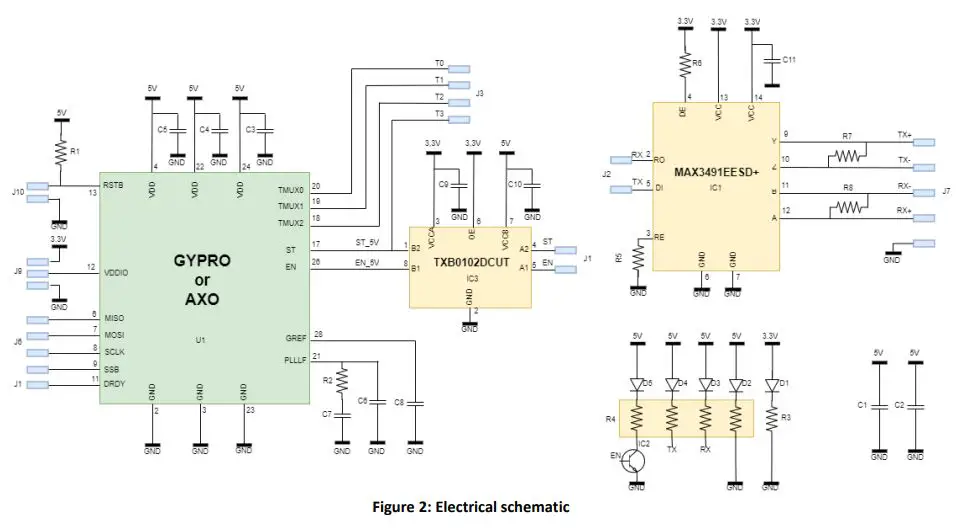
Electrical circuit
The following figure presents the electrical schematic of the board with its passive components (resistors & capacitances).
Electrical Characteristics
| Parameter | Min | Typical | Max | Units |
| 5V Power Supply (VDD) | 4.75 | 5 | 5.25 | V |
| Reference Voltage (VDDIO) | 1.8 | – | 5 | V |
| Current consumption 1) | 39 | mA | ||
| Output | Digital 24 bits | – | ||
| Digital interface | SPI | – |
The specified value represents the typical current consumption of GYPRO® and AXO® products.
Table 2: Electrical characteristics
| Passive components | Value |
| C1 | 10µF |
| C2 | 100nF |
| C3, C4, C5 | 100pF |
| C6 | 330nF |
| C7 | 5,6µF |
| C8 | 100µF |
| C9, C10, C11 | 100nF |
| R1 | 100kΩ |
| R2 | 5kΩ |
| R3 | 220Ω |
| R4 | 560Ω |
| R5, R6 | 4,7kΩ |
| R7, R8 | 120Ω |
Environmental specifications for GYPRO®AXO®-EVB3 are the following:
| Parameter | Condition | Min | Typ | Max | Units |
| Operating temperature range | -40 | +85 | °C | ||
| Humidity | At 45°C | 98 | % |
Table 4: Environmental specifications
- For more information about advanced use of GYPRO® and AXO® product, please refer to the dedicated datasheet, available on our website.
Caution!
The product may be damaged by ESD, which can cause performance degradation or device failure! We recommend handling the device only on a static safe work station. Precaution for the storage should also be taken. The sensor MUST be powered-on before any SPI operation. Having the SPI pads at a high level while VDD is at 0V could damage the sensor, due to ESD protection diodes and buffer
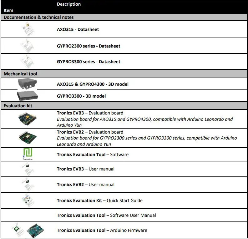
Available Tools and Resources
The following tools and resources are available on GYPRO® and AXO® webpages of Tronics website.
Should you encounter any issues while using GYPRO® or AXO® Evaluation Kit, please contact Tronics technical support by sending an email to [email protected].
©Copyright 2023 Tronic’s Microsystems S.A.. All rights reserved. The specification is subject to change without notice.


