Gentec V7 Accessories for BEAM diagnostics and attenuators
WARRANTY
The Gentec-EO accessories for beam diagnostics carry a one-year warranty (from date of shipment) against material and/or workmanship defects, when used under normal operating conditions. The warranty does not cover damages related to battery leakage or misuse. Gentec-EO Inc. will repair or replace, at Gentec-EO Inc.’s option, any accessories for beam diagnostics that prove to be defective during the warranty period, except in the case of product misuse. Any attempt by an unauthorized person to alter or repair the product voids the warranty. The manufacturer is not liable for consequential damages of any kind. In case of malfunction, contact your local Gentec-EO distributor or nearest Gentec-EO Inc. office to obtain a return authorization number. The material should be returned to:
Gentec Electro-Optics, Inc.
445, St-Jean-Baptiste, Office 160
Quebec, QC
Canada, G2E 5N7
Tel: (418) 651-8003
Fax: (418) 651-1174
E-mail: [email protected]
Website: www.gentec-eo.com
CLAIMS
To obtain warranty service, contact your nearest Gentec-EO agent or send the product, with a description of the problem, and prepaid transportation and insurance, to the nearest Gentec-EO agent. Gentec-EO Inc. assumes no risk for damage during transit. Gentec-EO Inc. will, at its option, repair or replace the defective product free of charge or refund your purchase price. However, if Gentec-EO Inc. determines that the failure is caused by misuse, alterations, accident or abnormal conditions of operation or handling, it would therefore not be covered by the warranty.
SAFETY INFORMATION
Do not use the BEAMAGE accessories if they look damaged, or if you suspect that the BEAMAGE accessories are not operating properly.
Caution:: Changes or modifications not expressly approved in writing by Gentec-EO Inc. may void the user’s authority to operate this equipment.
SYMBOLS
The following international symbols are used in this manual:
- Refer to the manual for specific Warning or Caution information to avoid any damage to the product.

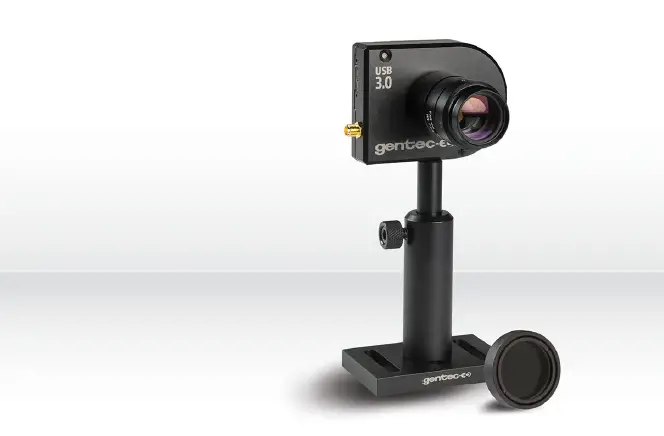
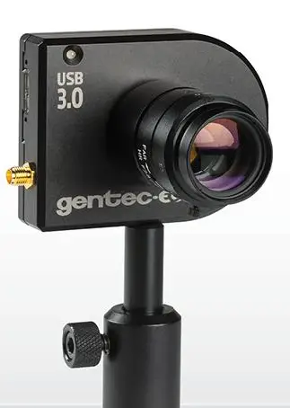
INTRODUCTION
HOW TO CAREFULLY MANIPULATE THE BEAMAGE WHEN USING ACCESSORIES
Profiling a laser beam is a nice and convenient complement to measuring its power or energy because it provides additional useful information that may help you determine if your lasers are operating optimally. For the most extended and complete use of your BEAMAGE beam profiling camera, optical components that provide attenuation, beam splitting, beam sampling, spectral sensitivity extension and large beam imaging may be required as practical accessories.
In most cases, these optical components are very easy to use and to manipulate. However, as a precaution, it is important to follow a few rules when fixing an accessory onto the camera’s aperture or when removing one from it. Doing so will prevent any damage that could be done to the CMOS sensor of the BEAMAGE.
Once they are stuck on the CMOS sensor, dust particles and other contaminants cannot be removed without serious risk of damaging it. Therefore, one must preferably:
Warning

Fix or remove accessories in a clean room or very clean environment.
Position the front cover of the camera downwards when fixing or removing accessories.
 POWER MANAGEMENT
 POWER MANAGEMENT
ND FILTERS (< 1W ATTENUATION)
Gentec-EO offers various SM1 threaded absorptive Neutral Density (ND) filters that can be stacked directly on the aperture of the BEAMAGE camera via a SM1 to C-mount adaptor. Subsequent filters can be stacked directly on each other. These filters have the ability to equally reduce the intensity of all wavelengths without affecting the wavefront of the beam or distorting the image. The attenuation is wavelength dependent see Figure 5. An empty SM1 threaded filter holder is available for those who would like to use their own ND filters with their camera. It holds 25 mm wide filters. Each filter and each holder comes with a SM1 to C-mount adaptor. Sets of 3 filters or 6 filters are also available. Optical density varies with the wavelength. To see the complete transmission spectrum, please refer to “Figure
- Transmission Curve of all ND Filters” on next page
For the BEAMAGE-FOCUS, Gentec-EO also offers 6 ND filters with a diameter of 50 mm, mounted in an SM2-threaded holder and with a T-mount adaptor.
Neutral Density Filters Specifications
| SM1-threaded | SM2-threaded | |
| Specified OD Spectral Range | 400 nm – 650 nm | |
| Spectral Range | 350 nm – 1600 nm | |
| Filter Diameter | 25 mm Ø | 50 mm Ø |
| Clear Aperture | 22.5 mm Ø (90% of diameter) | 45.7 mm Ø |
| Dimensional Tolerance | +0.0/-0.25 mm | |
| Optical Density Tolerance | ±5% | |
| Parallelism | < 10 arcsec | |
| Transmitted Wavefront Error | < λ/10 at 633 nm | N/A |
| Surface Flatness | < λ/4 | < λ |
| Surface Quality | 40-20 Scratch-Dig | |
| Maximum Power | 1 W | |
| Damage Thresholds | 100 W/cm2 or 3 J/cm2 | |
Available Products Characteristics
| Model | P/N | Description | Optical Density @ 633 nm | Equivalent Attenuation | Transmittance @ 633 nm | Substrate | Substrate Thickness |
| ND0.5 ND0.5-FOCUS | 201094 203403 | ND filter | 0.5 | (1/3.16) | ~32% | NG4 | ~0.91 mm |
| ND1.0 ND1.0-FOCUS | 201045 203404 | ND filter | 1.0 | (1/10) | ~10% | NG4 | ~1.89 mm |
| ND2.0 ND2.0-FOCUS | 201046 203405 | ND filter | 2.0 | (1/100) | ~1% | NG9 | ~1.40 mm |
| ND3.0 ND3.0-FOCUS | 201047 203406 | ND filter | 3.0 | (1/1000) | ~0.1% | NG9 | ~2.11 mm |
| ND4.0 ND4.0-FOCUS | 202600 203407 | ND filter | 4.0 | (1/10 000) | ~0.01% | NG9 | ~2.83 mm |
| ND5.0 ND5.0-FOCUS | 202601 203408 | ND filter | 5.0 | (1/100 000) | ~0.001% | NG9 | ~3.55 mm |
| NDSET-6 | 202605 | Set of all 6 filters | See above | – | See above | See above | See above |
| NDSET-3 | 202606 | Set of 3 filters (ND1, ND2, ND3) | See above | – | See above | See above | See above |
| ND-H | Call | ND filter holder | – | – | – | – | – |
Warning: When using multiple ND filters, it is necessary for the light to pass through the less attenuating filter first. For example, if you wish to have a 1/107 (ND 7.0) attenuation ratio, you need to put the ND 3.0 on the front and then the ND 4.0 filter between the ND 3.0 filter and the BEAMAGE camera.
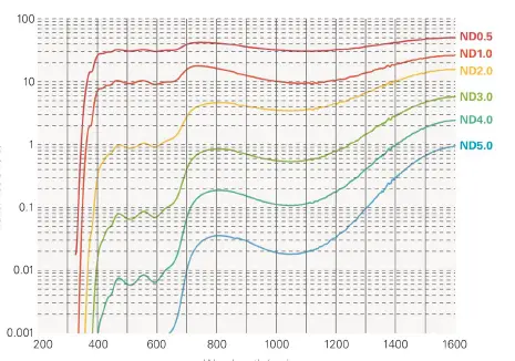
Figure 1: Transmission Curve of all ND Filters
WAVELENGTH MANAGEMENT
IR FILTER
Gentec-EO also offers a color glass filter specially designed for IR wavelengths. The IR filter transmits 70% of the incident light. It is particularly useful for applications with wavelengths ranging between 1250 nm and 1350 nm. Other wavelengths are stopped by the filter. The IR filter is SM1 threaded and comes with a SM1 to C-mount adaptor.
IR Filter Specifications
| BEAMAGE Spectral Range with IR filter | 1250 nm – 1350 nm |
| Diameter | 25 mm Ø |
| Clear Aperture | 80% of area |
| Dimensional Tolerance | +0.0/-0.2 mm |
| Thickness | 6.3 mm max |
| Parallelism | < 3 arcmin |
| Surface Flatness | < λ/4 |
| Maximum Power | 1 W |
| Surface Quality | 80-50 Scratch-Dig |
| Damage Threshold | 30 W/cm2 (typical) |
| Part Number | 202855 |
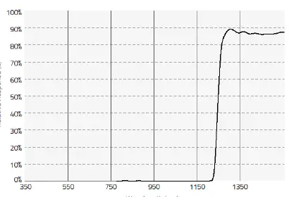
Figure 2: Transmission Curve of IR filter
IR ADAPTOR
The IR Adaptor takes advantage of a multi-photon absorption process to extend the sensitivity of the BEAMAGE beam profiling camera to a portion of the near-IR spectrum. The module converts wavelengths ranging between 1495 nm and 1595 nm (telecom wavelengths band) to shorter wavelengths ranging between 950 nm and 1075 nm. After going through an anti-reflection coated input window, the laser beam gets instantaneously converted with high resolution, low distortion and good uniformity. The IR Adaptor can be C-mounted onto the entrance port of the BEAMAGE camera.
Important: It is mandatory to factory adjust the IR Adaptor to its twin camera.
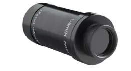
Figure 3: IR Adaptor
IR Adaptor Specifications
| Active Area | 27.5 mm Ø |
| IR Spectral Range | 1495 nm – 1595 nm |
| Peak IR Sensitivity | 1510 nm and 1540 nm |
| Converted Wavelengths | 950 nm – 1075 nm |
| Pixel Multiplication Factor | 3.29 |
| Minimum Beam Size | 230 µm |
| Maximum Beam Size | 19 mm |
| Maximum Resolution | 12 lp/mm over active area 40 lp/mm at sensor focal plane |
| Distortion | -1.0% barrel distortion (inverted image) |
| Linearity | Non-Linear, IR converted output ∝ IR input intensity ^1.41 |
| Spectral Transmission | 360 nm – 2000 nm @ F30.8 |
| Damage Threshold | 1 W/cm2 |
| Dimensions | 46 mm Ø x 97 mm L |
| Operating Temperature | -10°C to +40°C |
| Weight | 210 g |
| Part Number | 201061 |
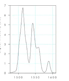
Figure 4: BEAMAGE-IR and IR Adaptor Excitation Spectrum
Important Steps to Follow When Using the IR Adaptor:
- Remove the ND4.0 filter from the camera
Remove the ND4.0 filter that is supplied with the BEAMAGE camera before using the IR Adaptor. - Determining and Entering the Pixel Multiplication Factor
The Pixel Multiplication of the IR Adaptor at the focus point is 3.29.
Enter this value in the software below Magnifying Lens. The on-screen dimensions will now be correct. - Screw the ND filter in front of the IR adaptor.
Depending on the laser source’s power, screw the appropriate ND filter in front of the IR adaptor. - Make a Background Subtraction or Select an Active Area
Since this optical component is suitable for ½’’ sensor format only (does not work for ⅔’’ sensor format), a portion of the sensor will not be available when using it. Therefore, it is necessary to make a background subtraction or to select an active area on the sensor via the PC-BEAMAGE software. - Apply the DE speckle Filter
The phosphor coated glass used inside the IR Adaptor produces speckles that may alter the intensity profile of the beam and thus affect the accuracy of the measurements. Therefore, it is important to use the DE speckle Filter when viewing a beam with the IR Adaptor because it will remove speckles and noise related to transmission of light through the phosphor coating. The DE speckle filter is a new and aggressive spatial filter that performs a 9×9 pixels simple averaging around each pixel, with all of the pixels having the same relative weight (1/81). Please note that using the DE speckle Filter can slightly reduce the resolution.
Warning: Please note that the minimum measurable beam diameter at a 50% clip level is approximately 230 μm. Any smaller beam will be significantly broadened by the point spread function of the phosphor.
UG11-UV – UV BANDPASS FILTER
Gentec-EO also offers a color glass filter specially designed for UV wavelengths. The UG11-UV filter transmits 20% to 77% of the incident light, depending on wavelength. It is particularly useful for applications with wavelengths ranging between 250 nm and 370 nm. Other wavelengths are stopped by the filter. The UG11-UV is SM1 threaded and comes with a SM1 to C-mount adaptor.
UG11-UV Bandpass Filter Specifications
| Spectral Range | 250 nm – 370 nm |
| Diameter | 25 mm Ø |
| Clear Aperture | 80% of area |
| Dimensional Tolerance | +0.0/-0.38 mm |
| Thickness | 3 mm |
| Thickness Tolerance | +0.0/-0.2 mm |
| Parallelism | < 3 arcmin |
| Maximum Power | 1 W |
| Surface Quality | 80 – 50 |
| Damage Threshold | 30 W/cm2 (typical) |
| Part Number | 202602 |
Warning: It is important to remove the ND 4.0 filter that comes with the BEAMAGE before using the UG11-UV Bandpass Filter.
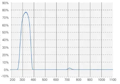
Figure 5: Transmission Curve of UG11-UV Bandpass Filter
UV CONVERTERS
UV converters take advantage of a phenomenon called fluorescence to extend the wavelength range of the BEAMAGE to the UV wavelengths. The fluorescent crystal is located at the entrance of the converter. It absorbs UV wavelengths and reemits longer wavelengths (visible spectrum), which are less energetic. The rest of the device is mainly composed of optics. An iris at the end controls the exposure on the sensing device.
The light emitted from the fluorescent crystal is non-coherent and non-collimated. The multiple lenses inside the converter compensating for this affect the beam size. Therefore, it is important to know that UV Converters have magnification properties, which are detailed in tables 9 and 10.
Like an IR adaptor, a UV converter is an extension tube that is simply fixed onto the aperture of the camera.
Important: It is mandatory to factory adjust the UV converter to its twin camera.
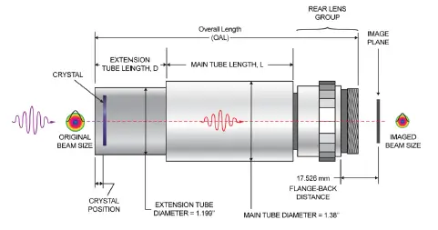
Figure 6: UV Converter Diagram
UV Converters Specifications (23 mm aperture)
| Model | BF23C23N | BF23G23N | BF23P23N | BF23R23N | |
| Input Aperture Ø [mm] | 23 | 23 | 23 | 23 | |
| Closest Standard Optical Camera Format | 2/3″ | 2/3″ | 2/3″ | 2/3″ | |
| Main Tube Length (L) [mm] | 76.3 | 76.3 | 76.3 | 76.3 | |
| Extension Tube Length (D) [mm] | 30 | 30 | 30 | 30 | |
| Overall Length (OAL) [mm] | 108 | 108 | 108 | 108 | |
| Max Input Beam Size [mm] | 13.8 x 18.4 | 13.8 x 18.4 | 13.8 x 18.4 | 13.8 x 18.4 | |
| Max Beam Size on CMOS [mm] | 5.3 x 7.1 | 5.3 x 7.1 | 5.3 x 7.1 | 5.3 x 7.1 | |
| Magnification (±10%) | 2.6 | 2.6 | 2.6 | 2.6 | |
| Crystal Type | C | G | P | R | |
| Wavelength Range [nm] | 110 – 225 | X-ray – 400 | 110 – 350 | 110 – 535 | |
| Relative Response | 193 nm | 22 | 480 | 48 | 100 |
| 248 nm | 0.17 | 480 | 15 | 8 | |
| 308 nm | 0.03 | 112 | 1 | 0.18 | |
| Saturation Level [mJ/cm2] | 193 nm | 400 | 10 | 30 | 50 |
| 248 nm | N/A | 10 | 30 | 400 | |
| 308 nm | N/A | 50 | 50 | 400 | |
| Damage Threshold [mJ/cm2] | 500 | 250 | 500 | 500 | |
| Max Average Power [W/cm2] | 2 | 2 | 2 | 2 | |
| Decay Time [μs] | 3 – 5 | 0.5 | 5 | 3000 | |
| Max Repetition Rate | 30 – 20 kHz | 200 kHz | 20 kHz | 30 Hz | |
| Part Number | 202325 | 202327 | 202329 | 202331 | |
Important Steps to Follow When Using a UV Converter:
- Remove the ND4.0 filter from the camera
Remove the ND4.0 filter that is supplied with the BEAMAGE camera before using a UV Converter. - Choosing the appropriate UV Converter
Gentec-EO offers a complete array of UV converters. For more details and information on how to choose the appropriate UV converter, please contact your local Gentec-EO representative. - Determining and Entering the Pixel Magnification Factor
Warning: When using a UV converter, you must enter its Pixel Multiplication Factor in the PC-BEAMAGE software.
Enter the value in the software in the Pixel Multiplication Factor section in the Setup Tab. The on-screen dimensions will now be correct.
BEAM SIZE MANAGEMENT
CL-25 AND CL-50 – CAMERA LENSES
A Camera Lens works by indirectly imaging on the sensor the reflection or the transmission of a beam (refer to Figure 7: Imaging a transmitted beam and Figure 8: Imaging a reflected beam) that previously went through a diffusing material such as glass.
It is necessary to use a Camera Lens to image beams that are larger than the CMOS sensor (11.3 mm X 6.0 mm) of the BEAMAGE beam profiling camera.
Warning: Please note that the image is inverted on the sensor since the mechanism of this optical device involves convergent lenses.
A Camera Lens can be directly C-mounted onto the aperture of the BEAMAGE camera as they are both C-mount.
Important Steps to Follow When Using a Camera Lens
- Choosing the appropriate Camera Lens
Camera Lens are offered with 2 different focal lengths, 25 mm and 50 mm. To determine which lens fits your requirements, refer to the table below.Names Part Number
Focal Length Horizontal FOV FOV at 1 m Minimum Working Distance
CL-25 202343 25 mm 14º 245 mm 0.5 m CL-50 202344 50 mm 7 º 120 mm 1 m To calculate the linear FOV (Field of View) at distances other than 1 m, simply multiply the value found in the table by the distance in meters.
- Remove the ND4.0 filter from the camera
Remove the ND4.0 filter that is supplied with the BEAMAGE camera before using a Camera Lens. - Install the optical setup
You can setup the BEAMAGE with a camera lens in transmission or reflection mode. Please refer to Figure 7 and Figure 8. Please adjust the focus of the Camera Lens in order to clearly see the target.
Warning: Please note that if the setup is in reflection mode, the viewing angle must be as small as possible to minimize distortion. - Flip the image horizontally
In the PC-BEAMAGE software select the “Flip Horizontally” option in the Setup Tab to compensate the Camera Lens’ inversion. Please refer to section 5.2.2 of the BEAMAGE user manual. - Subtract Background
Because the Camera Lens will image the laser, but also the entire scene, it is important to perform a background subtraction to only view the laser. - Determining and entering the Pixel Magnification Factor
Prior to profiling a beam with a Camera Lens, one must determine the Pixel Magnification Factor of the lens and enter its value in the PC-BEAMAGE software in order to have the exact beam dimensions. The “Pixel Multiplication Factor” section can be found at the bottom of the “Setup” tab.
It is possible to manually set a value for the Pixel Multiplication Factor. Simply enter the desired value in the white box and press enter. The beam dimensions will be adjusted accordingly. Otherwise, it is possible to follow the camera lens calibration steps in the “Camera Lens” panel. This panel can be opened by clicking the “Calibrate” button in the Pixel Multiplication Factor section or by selecting it in the Show/Hide Options button in the ribbon.- Once you are ready to start, click on the “Set now” button to set the centroid to the current position.
- Then, move the BEAMAGE (or the laser source) by a known distance along the X axis.
- Enter this distance (in mm) in the appropriate box.
- Finally, click on the “Calibrate” button to automatically set the Pixel Multiplication Factor (PMF) value found in the bottom of the “Setup” tab.
Once the Pixel Multiplication Factor is set, the beam dimensions will be adjusted to compensate for the magnification of the Camera Lens.
For more information about the automatic calibration of the Pixel Multiplication Factor, please refer to section 5.2.8 of the BEAMAGE user manual.
- Apply the DE speckle Filter
Any static diffusing material such as glass will show speckles, typically producing intensity variation of ± 20% and thus significantly affecting the accuracy of measurements. Apply the DE speckle filter to remove any unwanted intensity variations and to get the most accurate measurements. It is important to use the DE speckle Filter when imaging a beam with a Camera Lens because it will remove speckles and noisy signal related to irregularities of the diffusing material and distortions of the reflection-transmission optical process. Please note that using the DE speckle Filter can slightly reduce the resolution
Camera Lens Specifications
| CL-25 | CL-50 | |
| Focal lengths | 25 mm | 50 mm |
| Maximum beam size | 2000 mm X 2000 mm (not a limiting factor) | |
| Maximum measurable intensity / energy | Very high because of indirect mechanism | |
| Inverted image | Yes | |
| Beam distortion | Setup, lens aberration and speckles from diffusing glass | |
| Diffusing material needed | Yes | |
| Magnification calibration needed | Yes | |
| Possibility of wavelength conversion | Yes | |
| Optical filter needed | Rarely to never | |
| Removable | Yes | |
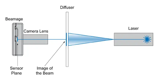
Figure 7: Imaging a transmitted beam
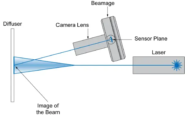
Figure 8: Imaging a reflected beam
APPENDIX A: WEEE DIRECTIVE
Refer to the UP User Manual if necessary (available at www.gentec-eo.com) for the power detector declaration of conformity.
WEEE compliance
These products comply with the European Directive 2012/19/EU – WEEE
Recycling and separation procedure for WEEE directive 2012/19/EU
This section is used by the recycling center when the detector reaches its end of life. Breaking the calibration seal or opening the monitor will void the detector warranty.
The complete accessory package can contain:
- 1 Accessory
- 1 Detector with DB-15.
- 1 Instruction manual
- 1 Calibration certificate
Separation
- Paper: Certificates (if applicable)
- Wires: Detector cable. (if applicable)
- Printed circuit board: inside the Detector (for -MT, -MA, -BT and -CP version only) or DB-15, no need to separate (less than 10 cm2). (if applicable)
- Glass: Optical component. (if applicable)
- Aluminum: Accessory housing. (if applicable)
CANADA
445 St-Jean-Baptiste, Suite 160
Quebec, OC, G2E 5N7
CANADA
T (418) 651-8003
F (418) 651-1174
[email protected]


