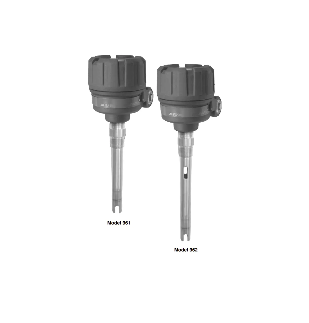
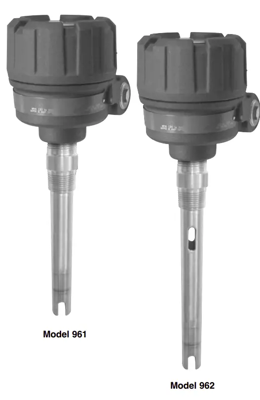
MAGNETROL Ultrasonic Single and Dual Point Level Switches
UNPACKING
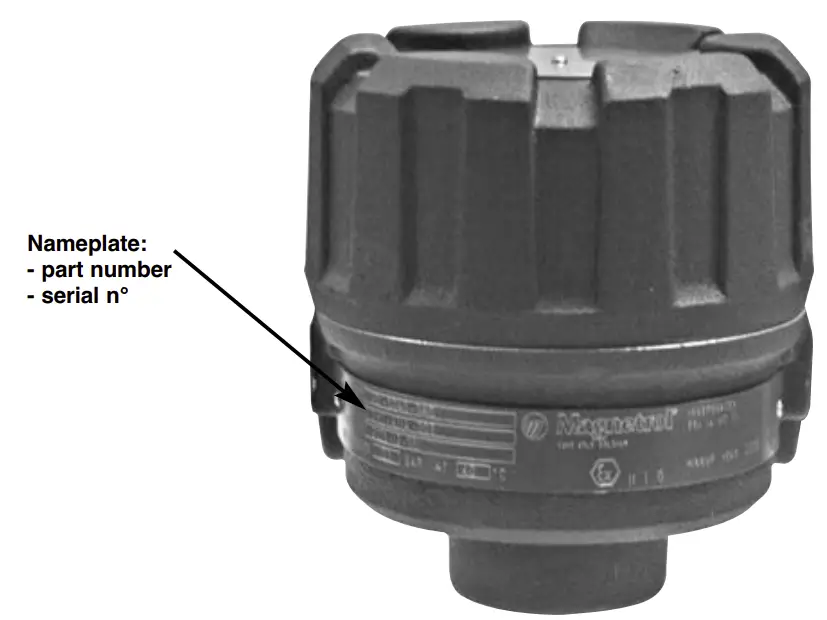
Unpack the instrument carefully. Make sure all components have been removed from the foam protection. Inspect all components for damage. Report any concealed damage to the carrier within 24 hours. Check the contents of the carton/crates against the packing slip and report any discrepancies to Magnetrol. Check the nameplate model number to be sure it agrees with the packing slip and purchase order. Check and record the serial number for future reference when ordering parts.
 | These units are in compliance with:
|
SPECIAL CONDITIONS FOR ATEX USE
- The enclosure contains aluminum and is considered to present a potential risk of ignition by impact or friction. Care must be taken during installation and use to prevent impact or friction.
- To maintain the T6 and/or T4 temperature code care shall be taken to ensure the “Enclosure Temperature” does not exceed 70 °C.
- The risk of electrostatic discharge shall be minimized at installation, clean non-conductive surfaces with moist cloth only.
- Contact the original manufacturer for information in the dimensions of flameproof joints.
- For installation with ambient temperature of 70 °C, refer to the manufacturer’s instructions for guidance on proper selection of conductors.
- The ultrasonic probe is only for use with the Echotel ultrasonic switch.
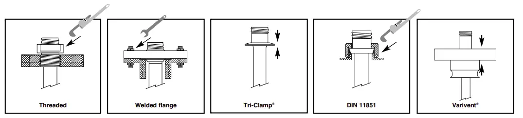
MOUNTING
WIRING
Echotel® 961 electronics
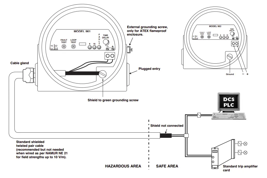
Important: Connect the unit to the ground for avoiding earth potential drifts.
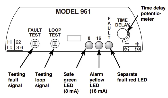
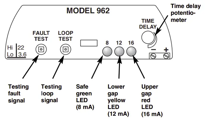
USER INTERFACE
- Echotel® 961

- Echotel® 962
SET UP AND FUNCTIONS
Set up
High – Low Level Failsafe selection:①
In «Hi» position, the current will shift to 12/16 mA (report alarm) when the transducer is wet.
In «Lo» position, the current will shift to 12/16 mA (report alarm) when the transducer is dry.
In both positions, the current will stay at 8 mA to report a safe condition.
Fault selection:
Select for which signal the unit should report a malfunction ≥ 22 mA or ≤ 3,6 mA
Time delay setting:
Turning the potentiometer clockwise will increase the time delay from 0,5 s to 10 s. Time delay is typically used where turbulence, boiling or splashing can cause false level alarms.
Indication
Echotel 961
| Failsafe mode① | Level | Output signal | 8 mA green LED | 16 mA yellow LED | Fault red LED |
| «Hi» High Level Failsafe | 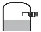 | 8 mA (± 1 mA) | ON | OFF | OFF |
 | 16 mA (± 1 mA) | OFF | ON | OFF | |
| «Lo» Low Level Failsafe | 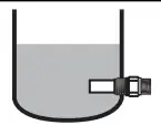 | 8 mA (± 1 mA) | ON | OFF | OFF |
 | 16 mA (± 1 mA) | OFF | ON | OFF |
Fault LED is ON = Fault indication
Echotel 962
| Failsafe mode | Level | Output signal | 8 mA green LED | 12 mA yellow LED | 16 mA red LED |
| «Hi» High Level Failsafe | 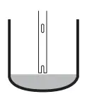 | 8 mA (± 1 mA) | ON | OFF | OFF |
 | 12 mA (± 1 mA) | OFF | ON | OFF | |
 | 16 mA (± 1 mA) | OFF | OFF | ON | |
| «Lo» Low Level Failsafe |  | 8 mA (± 1 mA) | ON | OFF | OFF |
 | 12 mA (± 1 mA) | OFF | ON | OFF | |
 | 16 mA (± 1 mA) | OFF | OFF | ON |
All LED’s OFF = Fault indication
①Use the following settings to replace Echotel 915 series with the new Echotel 961 series:
For High Level Failsafe, use «Lo» setting = low current draw (from 16 mA (safe) to 8 mA (alarm))
For Low Level Failsafe, use «Hi» setting = high current draw (from 8 mA (safe) to 16 mA (alarm))
MAINTENANCE
Manual Testing
Loop Test: (8 mA / 12mA / 16mA):
Pressing the “Loop Test” pushbutton, will manually test the loop and connected actuators/indicators. The loop test forces the output and corresponding LED’s to shift from 8 mA to 12 mA (only 962) to 16 mA back to 8 mA. The time delay setting is not active during testing.
Fault Test (3.6 mA /22 mA):
Pressing the “Fault Test” pushbutton for min 2 s, will manually test the fault output and connected actuators/indicators. The fault test simulates a circuit failure and forces the output to either ≤ 3.6 mA or ≥ 22 mA. The time delay setting is not active during testing.
Troubleshooting
Problem | Action/Indication | Solution |
| No loop signal | No LED’s are ON | Check wiring / input power Check for malfunction (962). See below |
| No change in output between wet gap / dry gap | Gap may be plugged by solids / dense foam | Clean the transducer |
| Gap is out of reach of liquid | Check mounting section and relocate the unit or check blocking valves. | |
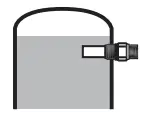
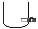
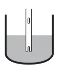
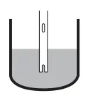
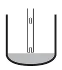
| Chattering output | Excessive aeration / Turbulence | Introduce a time delay Check input power Relocate the switch If installed horizontally, make sure the 961 transducer gap is oriented in a vertical position as shown in the mounting section. This allows proper drainage from the gap, and prevents air bubbles from accumulating in the gap. |
| Fault LED is ON (961) All LED’s OFF (962) | A system fault has been detected | Check input power |
| Press «Loop Test» pushbutton to identify the problem: * — * : 1 flash (red LED) | Check wiring between transducer and electronics or replace transducer. | |
| ** — ** : 2 flashes (red LED) | Replace electronics | |
| *** — *** : 3 flashes (red LED) | The unit senses excessive noise interference. Check shield connection or eliminate interference from a walkie-talkie, radio or other nearby source |
REPLACEMENT PARTS
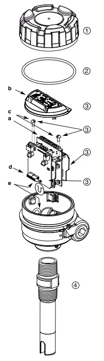
Replacing electronics/transducer
Echotel electronics can be removed in the field under process conditions. Follow below steps to exchange electronics/transducer:
Note: Adjust set up of the replacing electronics following the settings of the old electronics (see configuration section)
- Disconnect power before removing the housing cover
- Remove power/output wires (a)
- (Skip step 3 if hygienic housing.) Click out the protection cap of the electronics (b)
- Remove the 2 bracket screws and slide out electronics (c)
- Remove the transducer wires (see Wiring section) (d)
- Re-assemble following the same procedure in opposite way. Make sure that the tip on the bracket of the electronic block is seated properly in the corresponding recess in the housing base – (e)
Replacement parts
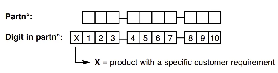

See nameplate, always provide complete partn° and serial n° when ordering spares.
 E X P E D I T E S H I P P L A N ( E S P )
Several parts are available for quick shipment, within max.
1 week after factory receipt of purchase order, through the Expedite Ship Plan (ESP).
Parts covered by ESP service are conveniently grey coded in the selection tables.
| No. | Description | Part Number |
| 1 | Cast aluminium cover (digit 10 = 0 or 1) Blind With window Cast stainless steel cover (digit 10 = 2 or 3) Deep drawn stainless steel cover | 004-9192-009 036-4410-010 004-9224-014
032-3934-001 036-5702-002 |
| 2 | “O”-Ring digit 10 = 0, 1, 2 or 3 digit 10 = 4 or 5 | 012-2201-237 012-2201-155 |
| 3 | Electronic module for industrial housing (digit 10 = 0, 1, 2 or 3) 961 962 Electronic module for hygienic housing (digit 10 = 4 or 5) 961 962 | 089-7259-005 089-7258-003 089-7256-003 089-7257-003 |
| 4 | Transducer | consult factory |
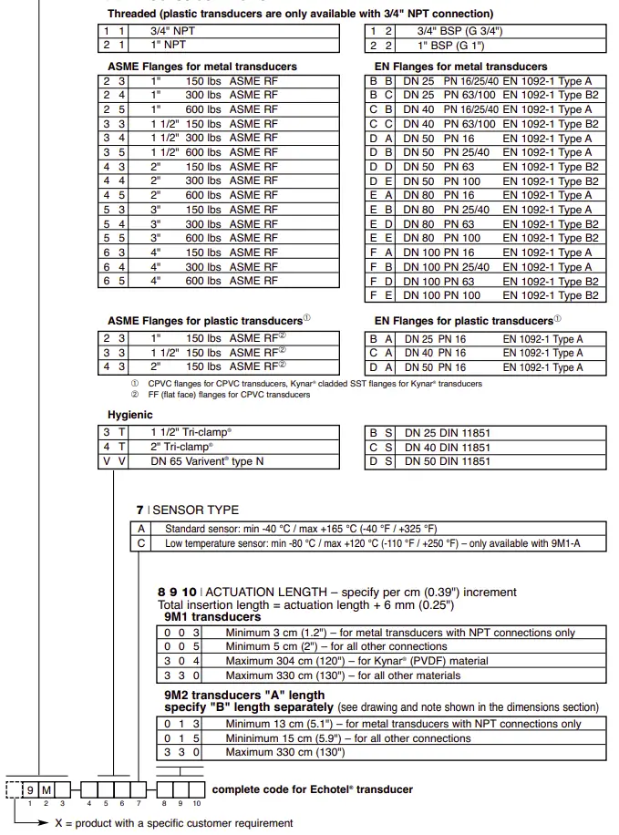
MODEL IDENTIFICATION
A complete measuring system consists of:
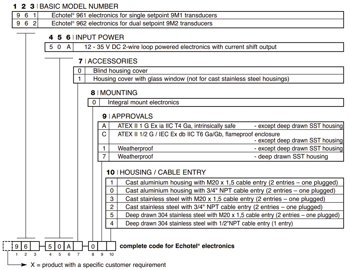
- Code for Echotel® electronics

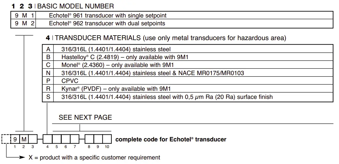
- Code for Echotel® transducer

MODEL IDENTIFICATION
2. Code for Echotel® transducer
SEE PREVIOUS PAGE
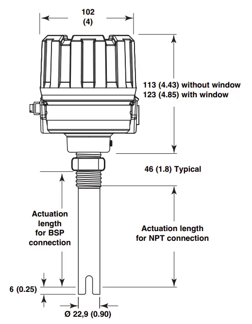
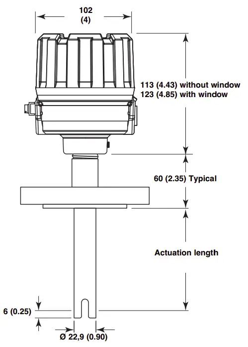
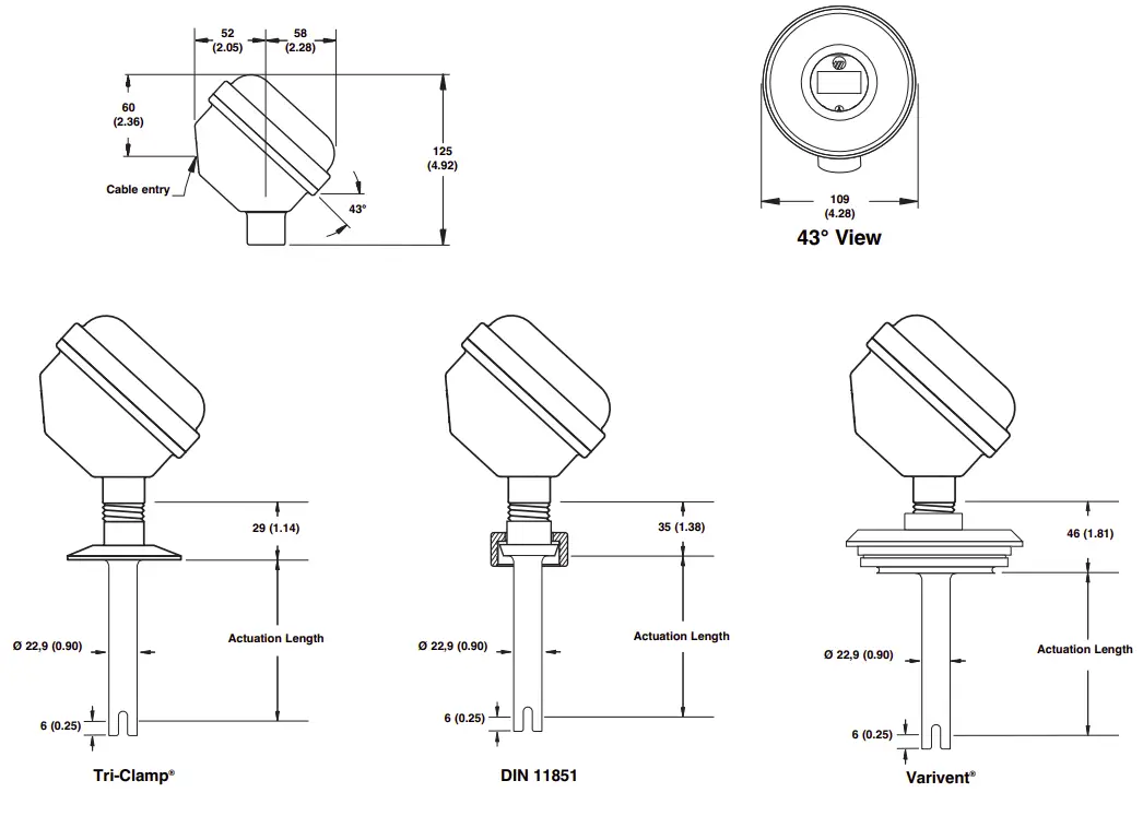
DIMENSIONS IN mm (inches)
- 961 – Threaded connection

- 961 – Flanged connection

- 962 – Threaded connection

- 962 – Flanged connection

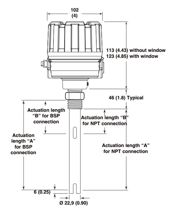
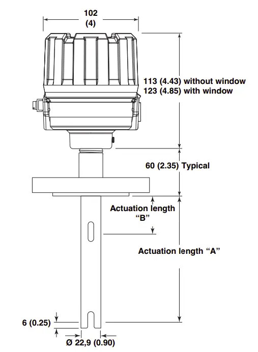
Note: – Difference between actuation lengths “A” and “B” must be min. 8 cm. – Max. length for dimension “B” is 322 cm
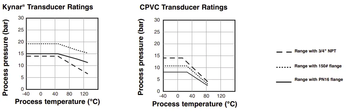
PRESSURE / TEMPERATURE RATINGS
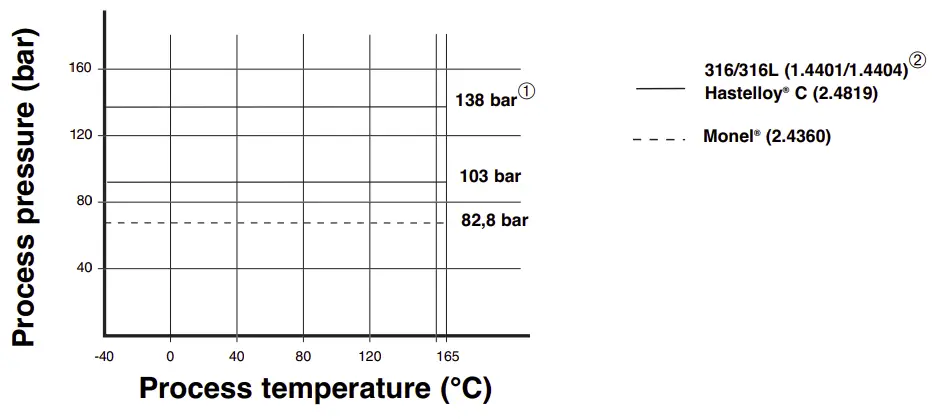
① Only applicable to NPT-connections with actuation length = 3 cm
and BSP/ASME/EN-connections with actuation length = 5 cm
② For low temperature sensor: from -80 °C up to +120 °C
SPECIFICATIONS
Electronics specifications
| Description | Specification | |
| Input Voltage | 2 wire loop powered, 12 – 35 V DC | |
| Power Consumption | < 1 Watt | |
| Output | 961: 8 mA (safe), 16 mA (alarm) ± 1 mA 962: 8 mA (safe), 12 mA (lower gap alarm), 16 mA (upper gap alarm) ± 1 mA 961/962: ≤ 3,6 or ≥ 22 mA error signal | |
| Time delay | 0,5 to 10 s adjustable (in addition to transducer response time) | |
| Indication | LED’s for process alarm status, malfunction (error of transducer, electronics or elec- trical noise interference) | |
| Selftest | Automatic | Continuously verifies electronics, transducer and noise interference |
| Manual | Via pushbutton for checking alarm output(s) and error output/function. | |
| Housing material | IP66, cast aluminium, cast stainless steel or deep drawn 304 stainless steel (IP 67) | |
| Approvals ① | ATEX II 1 G Ex ia IIC T4 Ga, intrinsically safe ATEX II 1/2 G Ex db IIC T6 Ga/Gb, flameproof enclosure IEC Ex d IIC T6 Ga/Gb + Ex ia IIC T4 Ga Overfill prevention TÜV – WHG § 63 / VLAREM II 5.17.7 Other approvals are available, consult factory for more details | |
| SIL (Safety Integrity Level) | Functional safety to SIL 2 in accordance to IEC 61508 – SFF > 90 % Full FMEDA report and declaration sheets available at request | |
| Electrical data | Ui = 28,4 V, li = 94 mA, Pi = 0,67 W | |
| Equivalent data | Ci = 10,4 nF, Li = 3 µH | |
| Shock/Vibration | ANSI/ISA-S71.03 Class SA1 (shock), ANSI/ISA-S71.03 Class VC2 (vibration) | |
| Net weight | Aluminium / Deep drawn 304 SST: 1 kg (2.2 lbs) – electronics only Cast SST: 2,5 kg (5.5 lbs) – electronics only | |
① Only available with cast aluminium or cast stainless steel housings
Performance
| Description | Specification |
| Response time | 0,5 s typical |
| Repeatability | ± 2 mm (0.078″) |
| Ambient Temperature | -40 °C to +70 °C (-40 °F to +160 °F) |
| Humidity | 0-99 %, non-condensing |
| Electromagnetic Compatibility | Meets CE requirements (EN 61326: 1997 + A1 + A2) and NAMUR NE 21 |
Transducer specifications
| Description | Plastic transducers | Metal transducers |
| Material | CPVC Kynar® (PVDF) | 316/316L SST (1.4401/1.4404) Hastelloy® C (2.4819) Monel® (2.4360) |
| Mounting | Threaded (NPT/BSP) – Flanged (ASME – EN) – Hygienic | |
| Actuation length | From 5 cm up to 304 cm (2″ up to 120″) – PVDF From 5 cm up to 330 cm (2″ up to 130″) – CPVC | From 3 cm up to 330 cm (1.2″ up to 130″) |
| Process temp. (consult temp/ press. graphs) | -40 °C to +120 °C (-40 °F to +250 °F) – PVDF -40 °C to +80 °C (-40 °F to +180 °F) – CPVC | -40 °C to +165 °C (-40 °F to +325 °F) – standard -80 °C to +120 °C (-110 °F to +250 °F) – low temperature version in 316/316L SST |
| Max pressure (consult temp/ press. graphs) | 13,8 bar @ +40 °C (200 psi @ +100 °F) for NPT threaded units | 82,8 bar (1200 psi) for Monel transducers Consult temp/press. graphs for other materials |
| Flanged models are downrated to the design pressure of the selected flange | ||
IMPORTANT
SERVICE POLICY
Owners of Magnetrol products may request the return of a control; or, any part of a control for complete rebuilding or replacement. They will be rebuilt or replaced promptly. Magnetrol International will repair or replace the control, at no cost to the purchaser, (or owner) other than transportation cost if:
a. Returned within the warranty period; and,
b. The factory inspection finds the cause of the malfunction to be defective material or workmanship.
If the trouble is the result of conditions beyond our control; or, is NOT covered by the warranty, there will be charges for labour and the parts required to rebuild or replace the equipment.
In some cases, it may be expedient to ship replacement parts; or, in extreme cases a complete new control, to replace the original equipment before it is returned. If this is desired, notify the factory of both the model and serial numbers of the
control to be replaced. In such cases, credit for the materials returned, will be determined on the basis of the applicability of our warranty.
No claims for misapplication, labour, direct or consequential damage will be allowed.
RETURNED MATERIAL PROCEDURE
So that we may efficiently process any materials that are returned, it is essential that a “Return Material Authorisation” (RMA) form will be obtained from the factory. It is mandatory that this form will be attached to each material returned. This form is available through Magnetrol’s local representative or by contacting the factory. Please supply the following information:
- Purchaser Name
- Description of Material
- Serial Number and Ref Number
- Desired Action
- Reason for Return
- Process details
Any unit that was used in a process must be properly cleaned in accordance with the proper health and safety standards applicable by the owner, before it is returned to the factory.
A material Safety Data Sheet (MSDS) must be attached at the outside of the transport crate or box.
All shipments returned to the factory must be by prepaid transportation. Magnetrol will not accept collect shipments.
All replacements will be shipped Ex Works.
Customer Support
European Headquarters & Manufacturing Facility
Heikensstraat 6
9240 Zele, Belgium
Tel: +32-(0)52-45.11.11
e-mail: [email protected]
www.magnetrol.com


