
mXion SWD 6 Outputs for Signal Lamps
Introduction
Dear customer, we strongly recommend that you read these manuals and the warning notes thouroughly before installing and operating your device. The device is not a toy (15+).
NOTE: Make sure that the outputs are set to appropriate value before hooking up any other device. We can’t be responsible For any damage if this is disregarded.
NOTE: The switch address is from CV120/121! For addresses < 256 you need only write to CV121 etc.!
General information
We recommend studying this manual thoroughly before installing and operating your new device.
NOTE: Some functions are only available with the latest firmware. Please make sure that your device is programmed with the latest firmware.
Summary of Functions
DC/AC/DCC operation, analog and digital! Switchable with loco or switch addresses
For all g scale switches and LGB® signals
Hear polarization with relay
Optionally for LGB® EPL® engines
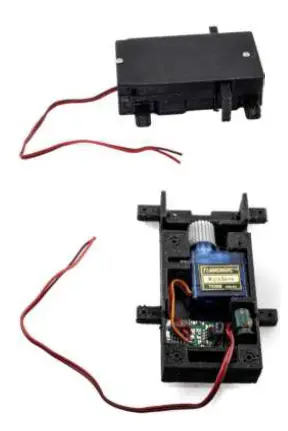
Optionally track break signal with engine Servoconrol + decoder in switch housing
Decoder + servo as single unit
Swinging, for e.g. bells
Re-Swinging, for e.g. signals
Extra switch output for laterns
Optionally flash light while servo moving Control via Speed Steps or Drive-Controller Switch output dimmable
Original switch/signal control
Switch time and speed configurable Full analog compatible
Compatible NMRA-DCC module Defined start switching position Automatic switch back functions Reset function for all CV values Easy function mapping
28 function keys programmable, 10239 loco adresses, 2048 switch adresses
14, 28, 128 speed steps (automaticly) Multiple programming options
(Bitwise, CV, POM accessoire decoder, register) Needs no programming load
Scope of supply
Manual
mXion SWD (exemplars)
Hook-Up
Install your device in compliance with the connecting diagrams in this manual. The device is protected against shorts and excessive loads. However, in case of a connection error e.g. a short this safety feature can’t work and the device will be destroyed subsequently.
Make sure that there is no short circuit caused by the mounting screws or metal.
NOTE: Please note the CV basic settings in the delivery state.
Rocking for signals and barriers.
The mode is activated with CV115 = 2. About CV113 is the speed for the teetering set.
About CV114 is the way (in degree) for the seesaw iss et.
Connectors switch engine
Connect the cable to the track or EPL® switch table. Intern is the function output between A1 and +24V.
Optionally, you can plug the SWD PLUG into the LGB® EPL® engine. 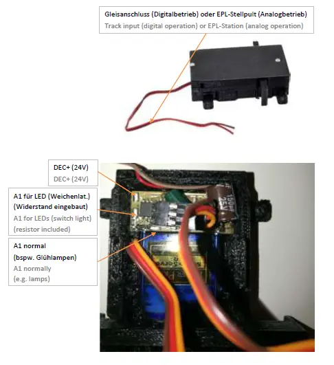 When using the the heart piece polarization is the flashing function of the output A1 automatically deavtivated. This works then only for heart polarization. You usually need this. A simple 24V relay with changeover contacts (these relays have a total of 5 connection pins). Think absolutely to a diode! A normal 1N4001 is sufficient for this.
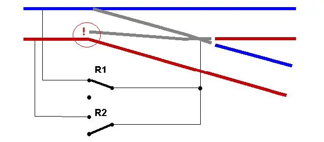
The side with the line on the diode must be to +24V. The other side to A1. The relay comes between +24V and A1.
Use our Relais (Art. No. 0016)
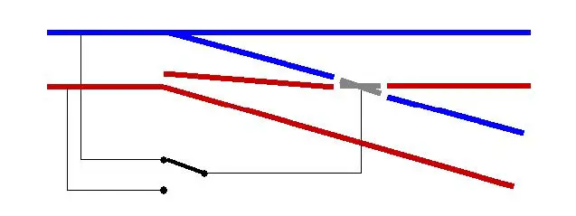
Normal switch
 Switch with connected heart
 Connectors signal engine
There is a modified version for wing signals of the SWD. This allows for a simple exchange of the EPL components. The electronics and connections are equal to those of the SWD. This version (SWD-PLUG) is also compatible with the LGB® turnout drives. An LGB® switch or signal drive. The lid of the LGB® drive must be (4 screws) unscrewed and onto the SWD-PLUG can be screwed on. Now the LGB® drive against the SWD exchanged and fully functional!
Delivery color: BLACK! 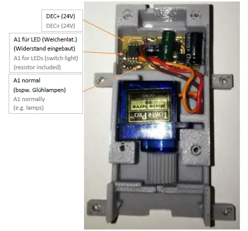 Please note when using the SWD-PLUG for EPL® switches as well as for signals, that there are 3 different types of the
LGB® EPL® drive. When using the SWD-PLUG as a replacement for an EPL® turnout drive must have the 3 walls of the cover in the area of the holes are cut off.
The latest version is extremely thin gear. The control rod has a wall directly in the field of gearing. The wand must completely cut off to the control rod benefits.
The second variant (usually with “NO 1201” inscription) a wide gear wheel and can also be directly install the intermediate gear of the EPL® drive and the supporting wall is still space.
The 3rd and oldest variants are a very long one gear which goes up to support wall.
It’s rough toothed the control rod hat here usually 2 tabs at the ends. Here the enclosed gear wheel against the pre-assembled gearwheel of the SWD-PLUG to be exchanged, leverage it carefully front the servo from the anchorage. Solve this already mounted gear with some power through lightly move (DO NOT TURN!). Glue the enclosed gearwheel with something second glue (CAUTION! Wave of servos!).
Optional: Please specify. Then the right toothed wheel is mounted directly supplied.
Connectors track break signals
The track break signal is also based on the SWD electronics and the switchboard. However, it is a separate device. The track break head is optionally with DB or DR(G) latern head. It is true to the original turn around and LED is switchable. LED color can be cold or warm white.
Delivery color: STEEL SILVER! 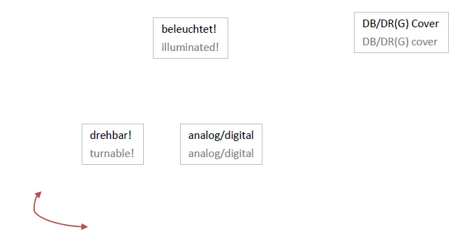
Product description
The mXion SWD is a very small servo drive of really smaller size of the LGB® EPL drive. At the same time is a fully functional servo decoder and one servo and the positioning mechanism. The servo encoder must only be connected to the digital track. From then on switches should be switched slowly.
In addition, various settings be made.
The switch is working also analog with for example the well-known LGB® EPL® control panel.
In addition, it is possible to switch the gate inverted too or a starting position (invertable) to activate. This switches the switch off the start to the specified position.
This is also adjustable.
Of course, the positioning speed and it can be specified, whether the switch is holding the position or not.
The SWD also has an external one switching output, which is dimmable. At this output which can be selected by loco and accesoir adress can be switched for example laterns or other loads up to 100 mA.
Also a resistor is included to connect LEDs directly.
Optionally for LGB® signals available.
In this case you need special case.
Programming lock
To prevent accidental programming to prevent CV 15/16 one programming lock. Only if CV 15 = CV 16 is a programming possible. Changing CV 16 changes automatically also CV 15.
With CV 7 = 16 can the programming lock reset.
STANDARD VALUE CV 15/16 = 225
Programming options
This decoder supports the following programming types: bitwise, POM and CV read & write and register-mode.
There will be no extra load for programming.
In POM (programming on maintrack) the programming lock is also supported. The decoder can also be on the main track programmed without the other decoder to be influenced. Thus, when programming the decoder can not be removed.
NOTE: To use POM without others decoder must affect your digital center POM to specific decoder adresses (e.g. Massoth® control panels)
Programming binary values
Some CV’s (e.g. 29) consist of so-called binary values. The means that several settings in a value. Each function has a bit position and a value. For programming such a CV must have all the significances can be added. A disabled function has always the value 0.
EXAMPLE: You want 28 drive steps and long loco address. To do this, you must set the value in CV 29 2 + 32 = 34 programmed.
Programming switch adress
Switch addresses consist of 2 values.
For addresses < 256 the value can be directly in address low. The high address is 0. If the address is > 255 this is as follows (for example address 2000):
2000 / 256 = 7,81, address high is 7
2000 – (7 x 256) = 208, address low is then 208.
Programm these values into the SW1 CVs CV120/121 and A2 (CV127/128).
Programming loco adress
Locomotives up to 127 are programmed directly to CV 1. For this, you need CV 29 Bit 5 „off“ (will set automaticly).
If larger addresses are used, CV 29 – Bit 5 must be „on“ (automaticly if change CV 17/18). The address is now in CV 17 and CV 18 stored. The address is then
like follows (e.g. loco address 3000):
3000 / 256 = 11,72; CV 17 is 192 + 11 = 203. 3000 – (11 x 256) = 189; CV 18 is then 189.
Reset functions
The decoder can be reset via CV 7. Various areas can be used for this purpose.
Write with the following values:
- 11 (basic functions)
- 16 (programming lock CV 15/16) 33 (function and switch outputs)
Function output features
| Funktion | A1 | Servo | Timevalue |
| On/Off | X | X | |
| Deactivated | X | ||
| Permanent-On | X | ||
| Forwards only | |||
| Backwards only | |||
| Standing only | |||
| Driving only | |||
| Timer sym. flash | X | X | X |
| Timer asym. short | X | ||
| Timer asym. long | X | ||
| Monoflop | X | ||
| Switch on delay | X | ||
| Firebox | |||
| TV flickering | |||
| Photographer flash | X | ||
| Petroleum flickering | |||
| Flourescent tube | |||
| Pairwise alternating | X | ||
| Autom. switch back | X | X | |
| Dimmable | X |
CV-Tabelle
S = Switch address, LS = Loco and switch address usable
| CV | Description | S | L/S | Range | Note | ||||||||
| 1 | Loco address | 3 | L | 1 – 127 | if CV 29 Bit 5 = 0 (automatically reset) | ||||||||
| 7 | Software version | – | – | read only (10 = 1.0) | |||||||||
| 7 | Decoder reset functions | ||||||||||||
| 3 ranges available | 11 16 33 | basic settings (CV 1,11-13,17-19,29-118) programming lock (CV 15/16) function- & Switch outputs (CV 119-129) | |||||||||||
| 8 | Manufacturer ID | 160 | – | read only | |||||||||
| 7+8 | Register programming mode | ||||||||||||
| Reg8 = CV-Address Reg7 = CV-Value | CV 7/8 don’t changes his real value CV 8 write first with cv-number, then CV 7 write with value or read (e.g.: CV 49 should have 3) è CV 8 = 49, CV 7 = 3 writing | ||||||||||||
| 11 | Analog timeout | 30 | 30 – 255 | 1ms each value | |||||||||
| 15 | Programming lock (key) | 225 | LS | 0 – 255 | to lock only change this value | ||||||||
| 16 | Programming lock (lock) | 225 | LS | 0 – 255 | changes in CV 16 will change CV 15 | ||||||||
| 17 | Long loco address (high) | 128 | L | 128 – 10239 | activ only if CV 29 Bit 5 = 1 (automatically set if change CV 17/18) | ||||||||
| 18 | Long loco address (low) | ||||||||||||
| 29 | NMRA configuration | 132 | LS | bitwise programming (add value) | |||||||||
| Bit | Value | OFF (Value 0) | ON | ||||||||||
| 1 | 2 | 14 speed steps | 28/128 speed steps | ||||||||||
| 2 | 4 | only digital operation | digital + analog operation | ||||||||||
| 5 | 32 | short loco address (CV 1) | long loco address (CV 17/18) | ||||||||||
| 7 | 128 | A1/SW1 with loco address | A1/SW1 with switch address | ||||||||||
| 48 | Switch address calculation | 0 | S | 0/1 | 0 = Switch adress like norm 1 = Switch adress like Roco, Fleischmann | ||||||||
| 49 | mXion configuration | 0* | LS | bitwise programming (add value) | |||||||||
| Bit | Value | OFF (Value 0) | ON | ||||||||||
| 0 | 1 | Servo no defined position | Servo defined position | ||||||||||
| 1 | 2 | Servo def. position „straight“ | Servo def. position „turned“ | ||||||||||
| 2 | 4 | Servo normal output | Servo inverted output | ||||||||||
| 3 | 8 | Servo don’t hold endposition | Servo hold endposition | ||||||||||
| 4 | 16 | A1 normal output | A1 inverted output | ||||||||||
| 5 | 32 | A1 normal function | A1 heart polarisation | ||||||||||
| 6 | 64 | A1 normal function | A1 flashes while switching | ||||||||||
| 7 | 128 | A1 normal function | A1 autom. on if moving | ||||||||||
| 102 | Switch position mid | 66 | LW | 0 – 255 | Turn area in degree |
| 103 | Bell-Mode drive on ramp | 15 | LW | 0 – 255 | 1 ms / value for ramp |
| 104 | Bell-Mode swing-off numbers | 8 | LW | 0 – 255 | numbers of swings in bell-mode |
| 113 | Servo-Mode special time swing speed | 5 | LW | 0 – 255 | Speed for Re-Swinging only if CV115 = 2 |
| 114 | Servo-Mode switch time | 20 | LW | 0 – 255 | CV115 = 1: Wait time at end position with time base 0,1 sec. per value CV115 = 2: Back-Swinging in degree |
| 115 | Servo-Mode | 0 | LW | 0 – 3 | 0 = normal function 1 = swinging (e.g. bells) 2 = re-swing at the end levels, e.g. for signals 3 = control via turn-wheel/speed steps |
| 116 | Servo wait time | 5 | LS | 1 – 20 | Fit to servo if bad moving |
| 117 | Switch position right | 70 | LS | 0 – 255 | Turn area in degree change if e.g. slider will be pressed hard |
| 118 | Switch position left | 35 | LS | 0 – 255 | |
| 119 | Servo command allocation | 1 | L | see attachment 1, active if CV 29 Bit 7 = 0 | |
| 120 | Servo address high | 0 | S | 1 – 2048 | active if CV 29 Bit 7 = 1 switch address for servo |
| 121 | Servo address low | 1 | S | ||
| 122 | Servo speed value | 15 | LS | 0 – 255 | Speed value 1 ms each value |
| 123 | Servo time for automatic switch back function | 0 | LS | 0 – 255 | 0 = off 1 – 255 = time base 0,25 sec. each value |
| 124 | Servo staytime hold time after reach end position | 0 | LS | 0 – 255 | 0 = off 1 – 255 = time base 0,1 sec. each value important, when drives peed is small |
| 125 | A1 command allocation | 2 | L | see attachment 1, active if CV 29 Bit 7 = 0 | |
| 126 | A1 dimming value | 100 | LS | 1 – 100 | dimming value in % (1 % ca. 0,2 V) |
| 127 | A1 address high | 0 | S | 1 – 2048 | active if CV 29 Bit 7 = 1 switch address for output A1 |
| 128 | A1 address low | 2 | S | ||
| 129 | A1 time for special function | 2 | LS | 1 – 255 | time base (0,1s / value) |
ATTACHMENT 1 – Command allocation
| Value | Application | Note |
| 0 – 28 | 0 = Switch with light key 1 – 28 = Switch with F-key | |
| +64 | permanent off | Not for Servo |
| +128 | permanent on | Not for Servo |
*SWD PLUG please set CV49 Bit 2 = 1 (inverted on) by signals!
Technical data
- Power supply:
10-27V DC/DCC
5-18V AC - Current:
5mA (with out functions) - Maximum function current:
A1 0.1 Amps.
Servomotor 0.5A Servo - Maximum current:
1 Amps. - Temperature range:
-20 up to 85°C - Dimensions SWD/SWD PLUG L*B*H (cm): 7*4*2
- Dimensions SWD BREAK L*B*H (cm): 3.5*4*19.5
NOTE: In case you intend to utilize this device below freezing temperatures, make sure it was stored in a heated environment before operation to prevent the generation of condensed water. During operation is sufficient to prevent condensed water.
Warranty, Service, Support
micron-dynamics warrants this product against defects in materials and workmanship for one year from the original date of purchase. Other countries might have different legal warranty situations. Normal wear and tear, consumer modifications as well as improper use or installation are not covered. Peripheral component damage is not covered by this warranty. Valid warrants claims will be serviced without charge within the warranty period. For warranty service please return the product to the manufacturer. Return shipping charges are not covered by micron-dynamics. Please include your proof of purchase with the returned good. Please check our website for up to date brochures, product information, documentation and software updates. Software updates you can do with our updater or you can send us the product, we update for you free.
Errors and changes excepted.
Hotline
For technical support and schematics for application examples contact:
micron-dynamics
[email protected]
[email protected]
www.micron-dynamics.de
https://www.youtube.com/@micron-dynamics


