BEAM 931 PotsDOCK Extreme Satellite Communication User Guide
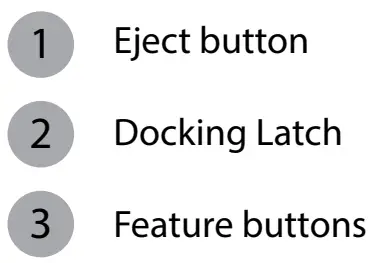
PotsDOCK Extreme Installation set up
Options
Tracking & Alert
Tracking & alert requires the GPS antenna and setup of the tracking and/or alerting messages in Eagle and in the Iridium Extreme Handset.
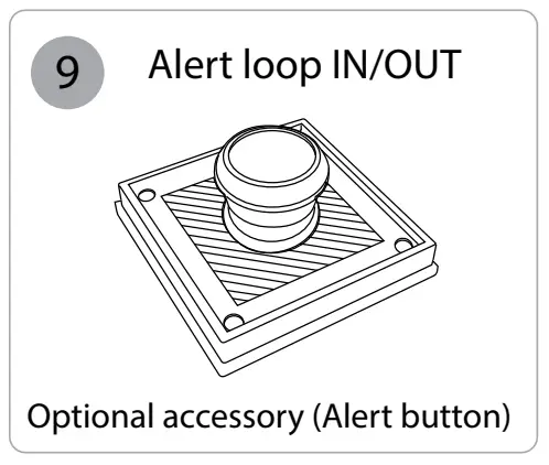
External Alert Loop Button:
Connect a Normally-CLOSED button, to the Brown and
Green wires (it can be extended for longer runs).
The loop needs to be OPEN (press button) for 2 seconds to activate Alert (SOS) mode.
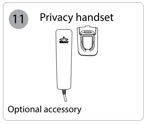
Privacy Handset:
- Mount the handset cup to the mounting plate.
- Mount the spacer plate and the mounting bracket, by using the longer screws provided with the kit. (Reinstalled the RAM arm bracket behind these plates).
- Connect the Privacy Handset 3.5mm plug into the loom socket connector.
- Privacy Handset must be returned to cup when not in use.
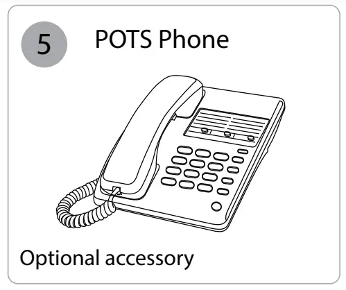
Pots/RJ11 Interface
- Mount the analogue phone, and plug the RJ11 cable (up to 600m length) into the PotsDOCK Extreme RJ11 port.
- Lift the RJ11 POTS phone handset “OFFHOOK” and listen for a dial tone.
- Dial (using the full country codes) on the RJ11 telephone keypad.
- Allow up to 5 seconds for the call to be issued handset, at which point Extreme to the Iridium the progress message appears on the Iridium Extreme handset.
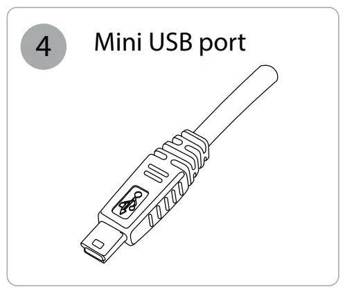
PotsDOCK Extreme USB Data Port
- The PotsDOCK Data Port on the rear. Drivers for this USB port can be downloaded from: www.beamcommunications.com/support
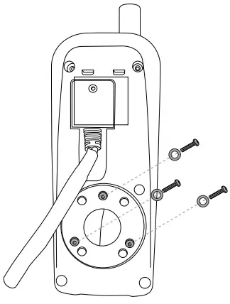
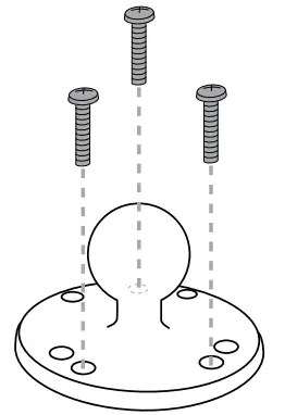
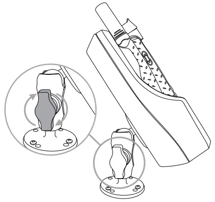
Mounting Cradle
The PotsDOCK Extreme is supplied with a universal RAM® mount bracket that enables mounting to any flat surface (vertical or horizontal) within a vehicle, or other required location.
- Attach one pivot base to the rear of the PotsDOCK Extreme using the M4 screws and washers supplied.

- Secure the second pivot base to the location you have selected for mounting the PotsDOCK Extreme. (Screws not supplied)

- Use the interconnecting arm of the RAM® mount to secure the PotsDOCK Extreme to the pivot base and tighten into the desired location firmly using the wing nut on the arm.

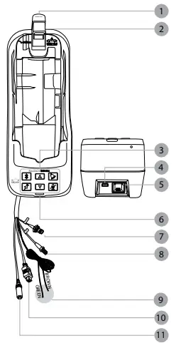
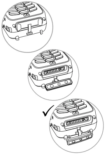
Inserting and Ejecting Extreme Handset
Inserting
- At the base of the Iridium Extreme handset there is an accessory connector cover. Open the cover and move it to the back of the handset, securing it to the two rear retaining features.

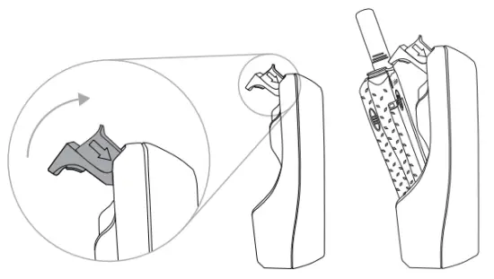
- Press down the latch button and then gently rotate it up to open the latch. Place the Iridium Extreme handset into the PotsDOCK Extreme.

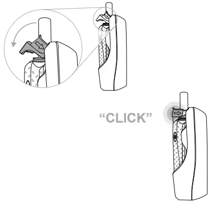
- Lift the latch back over the handset until it Click’s into place.

Removing
To remove the handset, first press the eject button and then rotate the latch up away from the handset. The handset can now be slid up and out of the PotsDOCK. Refit the accessory connector cover to maintain the IP rating of the Iridium Extreme handset.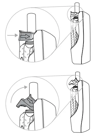
Iridium Antenna Connection
The antenna connections exit from the rear of the PotsDOCK Extreme cradle, via the antenna loom. There are two RF connections required, the Satellite TNC Female Connector and GPS SMA Female connector. Refer to the antennas installation guide for antenna mounting and location requirements.
![]() WARNING
WARNING
DO NOT pull with force on the cables from the rear of the PotsDOCK. Please install strain relief clamping for the antenna cables where required.
Correct installation of the antenna system is a vital part of the PotsDOCK system, to ensure reliable functionality, and drop-free calls.
PotsDOCK Extreme Front Panel
| LOCATION | BUTTON MODE | ACTION | LED/SOUND |
 | Mute press On/of | In a Call: Mute the microphone (uplink) on the Bluetooth Handsfree or optional privacy handset. | LED turns RED Muted LED turns OFF Not muted |
 or  | Up/Down | In a Call: Increase/decrease volume on the audio device in use | Audio will sound louder/quieter with each press. |
| Out of Call or Incoming Ring: Increase/decrease volume of incoming ring tone on the internal speaker. (The lowest setting will silence the Ringer). | A beep will sound indicating the increased/ decreased ring tone volume of the internal speaker | ||
| Brightness Mode: Increase/decrease the LED intensity | All Button LEDs will be increased/decreased with each press. | ||
| + | Brightness – dual button simultaneous press (2 sec) | Out of Call: Enter LED brightness change mode. Then Press UP and/ or DOWN arrows to vary intensity Mode will automatically exit after 5 seconds after the last button press. | Status LED flashes YELLOW 3 times and all Button LED’s will change WHITE. A single beep will sound when entering brightness change mode. A short double beep will sound when exiting change mode. |
 | Ringer Single Press | Not in Call: Cycle through the ring tones for the internal buzzer. The last Ringer type sounded is then saved. | Ring tone playback and the output device changes. LED FLASHING (Fast) BLUE when Ring Tone is sounded |
 | Single Press (no beep sound) | When Bluetooth is OFF: Turns ON Bluetooth function. | LED changes from OFF to FAST FLASHING in BLUE when searching Bluetooth device(s). LED turns solid BLUE when connected |
| If Bluetooth connected but NOT used in Call: Transfer the audio to the Bluetooth device. | LED changes from Solid BLUE to SLOW FLASHING in BLUE | ||
| Bluetooth Device being Used in Call: Transfer the audio to Privacy handset if activated | LED changes from Slow Flashing to solid BLUE | ||
| Single Press 1.5 sec (until 1 beep sounds) | Bluetooth function is ON: Turns OFF Bluetooth function | LED turns OFF | |
| Single Press 5 sec (until 2 beep sounds) | Bluetooth function is ON: Bluetooth is set to discovery mode for pairing to Bluetooth devices | LED is FAST FLASHING ORANGE and BLUE, and then turns solid BLUE when paired and connected. | |
| Single Press 10 sec (until 3 beep sound | Bluetooth is ON or OFF: Clear all paired Bluetooth devices and turn off Bluetooth function | LED turns OFF | |
 | Single Press (until 1 beep sounds) | In Tracking Mode*: Send a tracking message to the pre-configured destination in the Extreme Handset | LED flashes GREEN for 5 seconds. A beep will sound to indicate that a tracking message is to be sent# |
| Single Press 5 sec (until 2 beeps sound) | Enables / Disables Track button | LED Solid GREEN is enabled, LED OFF is disabled |
* This action is optional, and only when tracking for your Extreme Handset is configured and activated. Using the Track button only initiates the command to send a Quick GPS message – check that the Extreme Handset is configured correctly.
# A beep will only sound if audible alerts are enabled in Eagle
BEAM Communications Pty Ltd
8 Anzed Court, Mulgrave
Victoria, 3170, AUSTRALIA
Tel: +61 3 8588 4500
Fax: +61 3 9560 9055
Info: [email protected]
Support: [email protected]
www.beamcommunications.com


