
REACH WIRELESS RW1000-600APO Optical Smoke Detector

Product overview
- Product REACH Wireless Optical Smoke Detector
- Part No. RW1000-600APO
- Digital Communication Apollo protocol compatibility is handled via the Loop-Interface device, RW1700-030APO. See product for more detail
Product information
The RW1000-600APO is a wireless addressable optical smoke detector that utilised dual-optical smoke detection technology for improved performance; maintaining the highest levels of false-alarm rejection.
- Twin alarm, bi-colour LEDs for 360° visibility
- Advanced dual-optical chamber design
- Advanced drift compensation
- Bi-directional wireless communication
- Dual channel redundancy
- Ten year battery life
- Five year product warranty
Technical data
All data is supplied subject to change without notice. Specifications are typical at 24 V, 25°C and 50% RH unless otherwise stated.
| Detection principle | Photo-electric detection of light scattered in a forward direction by smoke particles |
| Communication Range between Loop-Interface and Devices | 100 m (in open space) |
| Field Device Radio Frequency Channel Pairs | 22 pairs |
| Status LED | Green and Red |
| Radiated Power | 14 dBm (25 mW) |
| Battery Type | 2x VARTA CR123A Lithium 3 V, 1250mAh typical |
| Battery Lifespan | 10 years in normal operation with good signal strength (no dropped messages) |
| Operating Temperature | -10°C to +55°C |
| Maximum Relative Humidity (non-condensing) | 95% |
| IP Rating | 40 |
| Standards and approvals | EN54-7, EN54-25 |
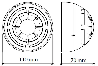
| Dimensions | 110 mm diameter x 70 mm height |
| Weight (including base and batteries) | 190 g |
Operating Principles
The REACH Wireless Optical Smoke Detector features an advanced dual-optical chamber design.
Status LED
It also includes a 360° LED indicator which illuminates red or green to indicate status conditions
| Table 1: REACH Wireless Device Status & LED Indication | |
| Device Status | LED Indication |
| Power Up | Blinks green four times |
| Power Up (dip-switch ON) | Blinks red four times |
| Entering Wake-Up | Blinks alternatively green/red four times |
| Link Success | Blinks green four times, then repeats |
| Link Failure | Enters wake-up mode and signals ‘Entering wake-up mode’ following this failure |
| Normal Condition | LED off |
| Alarm | Red 1s, period 2s |
| Battery Faults | LED off |
| Tamper Fault | LED off |
| Replaced | Blinks amber two times |
Device Addressing
Device addressing is handled by the REACH Wireless LoopInterface device (RW1700-030APO). Devices are soft-addressed automatically when pairing with the Loop Interface and can be changed manually. Hardaddressing using Apollo XPERT cards are not supported.
Communication
REACH Wireless Devices use ‘radio-frequency’ wireless communication to connect to the Loop-Interface. The Loop-Interface (RW1700-030APO) translates the wireless communication into wired Apollo protocol communication, with each device addressable individually by the fire panel. See datasheets for the Loop-Interface for more information.
Maintenance and Service
Maintenance must be performed in accordance with all applicable standards. Clean the detector externally using a soft damp cloth. For full cleaning and recalibration detectors should be returned to Apollo Fire Detectors.
Tamper detection
REACH Wireless devices contain an anti-tamper mechanism. In the event of removal from its base, it sends a tamper detection message to the Loop-Interface. Tampering detection is not signalled visually by the device LED.
Base Compatibility
This device is supplied with a standard wireless base and is compatible with the following AV bases:
| Table 2: REACH Wireless Base Compatibility | |
| Part Number | Product Name |
| RW1300-110APO | REACH Wireless Sounder Base |
| RW1300-210APO | REACH Wireless Sounder VAD Base (White Flash) (C-3-15) |
| RW1300-211APO | REACH Wireless Sounder VAD Base (Red Flash) (C-3-10) |
Batteries
REACH Wireless devices are supplied with two CR123batteries, battery A and B. The device switches periodically between the two batteries on a controlled sequence. For correct operation of the device, both batteries are required with adequate capacity reserves. When battery A reaches a low power threshold, it will trigger a fault. This fault requires both batteries to be replaced in every instance as both batteries should be discharging equally. When one (or both) batteries lack power, the Loop-Interface receives a low battery message and will signal this event on its in-built display, as well as relay the low battery message to the fire control panel. The battery fault will also be signalled by the device itself through its LED indicators if programmed (see table 1).
EMC Directive 2014/30/EU
REACH Wireless Optical Smoke Detector complies with the essential requirements of the EMC Directive 2014/30/EU, provided that it is used as described in this datasheet. A copy of the Declaration of Conformity is available from Apollo on request. Conformity of the REACH Wireless Optical Smoke Detector with the EMC Directive does not confer compliance with the directive on any apparatus or systems connected to it.
Construction Products Regulation (EU) 305/2011
The REACH Wireless Optical Smoke Detector complies with the essential requirements of the Construction Products Regulation (EU) 305/2011 A copy of the Declaration of Performance is available from Apollo on request
36 Brookside Road, Havant Hampshire, PO9 1JR, UK.
- Tel: +44 (0)23 9249 2412
- Fax: +44 (0)23 9249 2754
- Email: [email protected]
- Web: www.apollo-fire.co.uk
All information in this document is given in good faith but Apollo Fire Detectors Ltd cannot be held responsible for any omissions or errors. The company reserves the right to change the specifications of products at any time and without prior notice.


