BT QUICK INSTALLATION INSTRUCTIONS
![]()
 |  |  |  |  |
| Company’s offical website | PV Master App | SEMS Portal App | SEMS Portal website www.semsportal.com | |
| http://en.goodwe.com | https://www.semsportal.com/home/pvmaster | https://www.semsportal.com/home/AppDownload | https://www.semsportal.com | https://www.linkedin.com/company/jiangsu-goodwe-power-supply-technology-co-ltd-/ |

Step1 Instructions for quick installation
Step2 SOP of battery connection
Step3 Wi-Fi configuration instruction
Note:
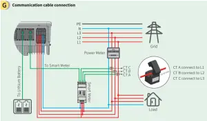
1. Connect to battery communication cable. (Battery fails to work if communication fails)
2. Connect to Smart Meter communication cable. (Could be extended to a max of 100m)
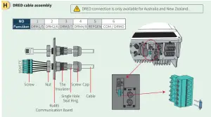
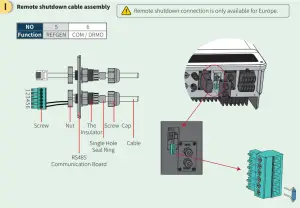
1. Plug out the 6-pin terminal and dismantle the resistor on it.
2. Plug the resistor out, leave the 6-pin terminal for the next step.
Note: The 6-pin terminal in the inverter has the same function as the DRED device. Please leave it in the inverter if no external device is connected.
J Wiring system for BT series hybrid inverter
Note: This diagram indicated the wiring structure of the BT series AC coupled inverter, not the electric wiring standard.
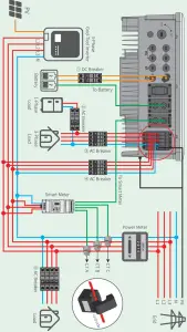
Please select Breaker according to the specification below.
| Inverter | |||
| GW-BT | 40A/600V DC breaker | 25A/400V AC breaker | Depends on household loads |
| GW6K BT | 25• /400V AC breaker | ||
| GW8K-BT | 32A/400VAC breaker | ||
| G 10K-13T | 32A14001 AC breaker | ||
For batteries with attached breakers, the external DC breaker could be omitted.
2. Please use CT A for L1, CT B for L2, and CT C for L3, and follow the “House(K) →Grid(L)” direction to do the connection.
Step 2. SOP of battery connection with ET inverter
Note: This manual only tells connection methods between battery and inverters. For other operations on battery, please refer to the battery user manual. (This quick installation instruction only includes parts of batteries, if there is a subsequent increase in battery, there will be no further notice.)
1. BYD
For the BYD B-BOX series with the hybrid inverter.
Note: In the gridless area, the battery does not support off-grid applications. (There will be no further notice if this entry is subject to change)![]() Make sure that the inverter and the battery pack are turned off before connecting the battery pack to the inverter.
Make sure that the inverter and the battery pack are turned off before connecting the battery pack to the inverter. To connect the cables from the inverter to the BYD battery pack, take the following steps:
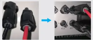
Connect the power cables to the terminal block of the BYD battery pack. Connect the negative cable to the position “P-” and the positive cable to the position “P+”.
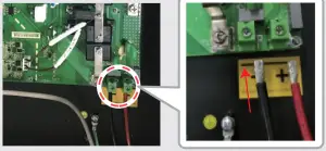
Connect the other end of the power cable to the terminal block of the hybrid inverter.
The communication cable for the battery is attached to the inverter.
Please use this cable as a battery communication cable.
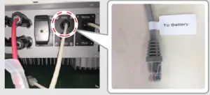
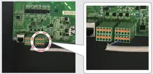
The other side of the “To Battery” cable should be connected to the CAN(Control(Controller) Area Network) port of the BYD BMU (Battery management unit ) box. Before this, you should pick out the blue-white line and the blue line.
Then, connect the blue-white line to the second port, and connect the blue line to the third port.
On PV Master, the user should choose the right battery type used in your system in the “Battery Model” selection, otherwise, battery communication will fail.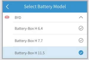
After all connections and settings have been done, please check if battery communication is OK on PV Master → Param → BMS Status, which should indicate “Normal”.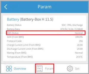
2. Pylon
For the POWER CUBE-H1 series with the hybrid inverter.
Make sure that the inverter and the battery pack are turned off before connecting the battery pack to the inverter.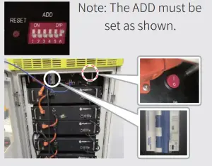 o connect the battery packs in series, follow the instructions below.
1. Connections between BMU and Pylon battery packs: To contact the power cable, connect “B+” of BMU to “B+” of the first battery pack, and connect “B-” of BMU to “B-” of the last battery pack. To connect the communication cable, connect “Link Port” of BMU to “Link Port 0” of the first battery pack.
2. Connections between adjacent Pylon battery packs: To connect the power cable, connect “B+” with “B-” between adjacent battery packs. The orange end corresponds to “B+”, the black end corresponds to “B-“. To connect the communication cable, connect “Link Port 1” to the next battery pack’s “Link Port 0” in tur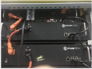
To connect the cables from the inverter to the Pylon battery pack, take the following steps. Connect the power cables to the terminal block of Pylon Battery management unit BMU). Connect the negative black cable to the position “D-” and the positive orange cable to the position “D+”.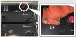
Connect the other end of the power cable to the terminal block of the hybrid inverter.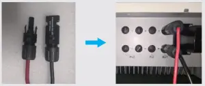
The communication cable for the battery is attached to the inverter. Please use this cable as a battery communication cable.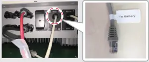
The other end of the “To Battery” cable should be connected to the CAN port of the Pylon battery management unit (BMU).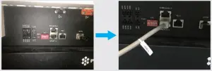
On PV Master, you should choose the right battery type used in your system in the “Battery Model” selection, otherwise, battery communication will fail.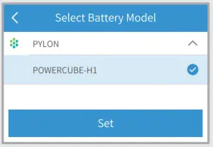
After all connection and settings have been done, please check if battery communication is OK on PV Master → Param → BMS Status, which should indicate “Normal”.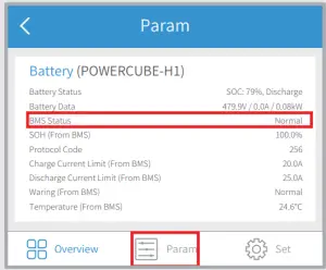
Step 3. Wi-Fi configuration instruction
Note: Wi-Fi configuration could also be done on PV Master App. For details, please download “PV Master Operation Introduction” from www.goodwe.com
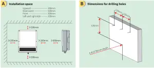
A Preparation
1. Power Wi-Fi inverter (or Power on inverter) on.
2. Power router on.
B Connect to “Solar-WiFi”
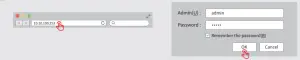
B-3: Enter User name: admin, Password: admin, click OK
C Preparation
Click “Start Setup”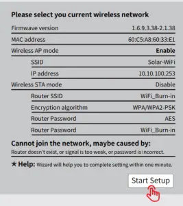
The Wi-Fi module refers to the “Device Information” column left.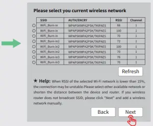
If the router is not on the site list, please refer to No.4 in “Troubleshooting”.=
Connect to “Solar-WiFi” Fill in the router password and click “Next”.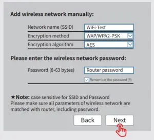
Please make sure all parameters of the wireless network are matched with the router’s, including password
Note: The “Solar-WiFi” signal will disappear after the inverter is connected to the WiFi router. Turn off the router or do Wi-Fi reload operation via a button on inverter if you
Troubleshooting
No. 1 | Problem | Checking items |
| Cannot Find Solar-WiFi Signal | 1. Make sure inverter is powered on; 2. Move your smart device closer to the inverter; 3. Restart inverter; 4. Do the ‘WiFi Reload” operation by referring to the user manual. | |
| 2 | Cannot connect to Solar-WiFi Signal | 1. Try password: 12345678; 2. Restart inverter; 3. Make sure there is no other device connected to Solar-WiFi; 4. Do the ‘WiFi Reload” operation and try again. |
| 3 | Cannot log in website 10.10.100.253 | 1. Make sure user name and password are both admins; 2. Do ‘WiFi Reload’ operation and try again; 3. Try another browser (suggest using Google, Firefox, IE, Safari, etc.); 4. Make sure the website is 10.10.100.253 |
| 4 | Cannot find router SSID | 1. Move the router closer to the inverter or use a Wi-Fi repeater device; 2. Connect to the router and log in to the setting page to check the channel. Please make sure the channel is not higher than 13. Otherwise, modify it. |
| 5 | Cannot connect to the router | 1. Restart inverter. 2. Connect to Solar-WiFi and log in again, check the “SSID”, “Security Mode”, “Encryption Type” and “Pass Phrase” is matching with that of the router or not; 3. Connect to router and login to check if the connection reaches the maximum amount or not, and to check the channel it uses. Please make sure the channel is not higher than 13. Otherwise, modify it; 4. Restart router; 5. Move the router closer to the inverter or use a Wi-Fi repeater device. |
| 6 | After configuration, WiFi LED on inverter blink four times repeatedly | 1. Connect to the router and visit the portal www.semsportal.com. |
| Check if the portal is available or not; 2. Restart router and inverter. Activate \ Cln to Settin |


