![]()
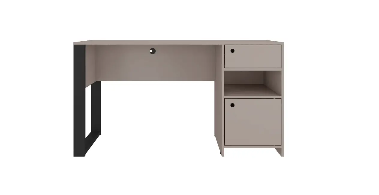
MODEL RTA-954D
ASSEMBLY INSTRUCTIONS
Thank you for purchasing our product.
REV.CMN-6659-0622

RTA-954D

- Please read carefully the assembly instructions before the installation.

- Do not discard this manual or any of the packaging material until the unit has been completely assembled.

- Might require two people.
MAIN PARTS LIST
| 1 Left base x1 | 2 Left support x2  | 3 Left panel x1  | |
| 4 Left back panel x1 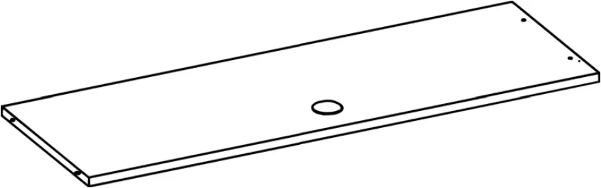 | 5 Middle vertical panel x1  | ||
| 6 Bottom panel x1  | 7 Door x1  | 8 Middle horizontal panel x1 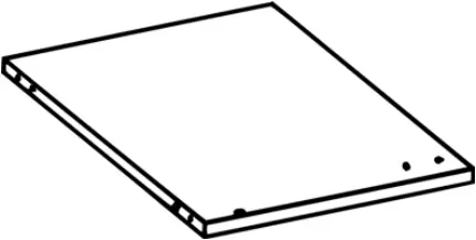 | 9 Right support x1 |
| 10 Right panel x1 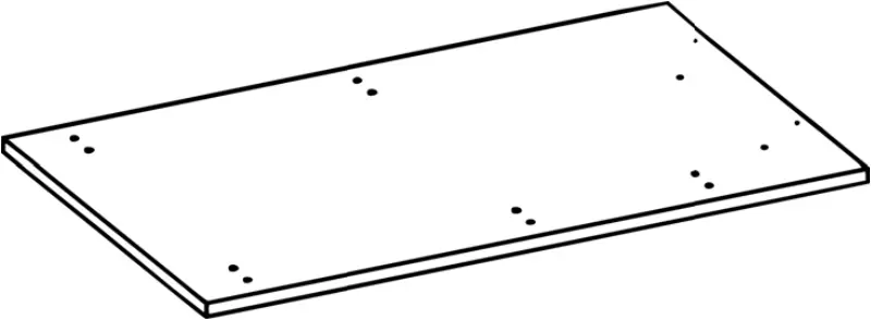 | 11 Drawer front panel x1 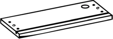 | 12 Drawer side panel x2 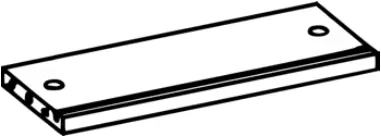 | |
| 13 Drawer back panel x1 | 14 Tabletop x1 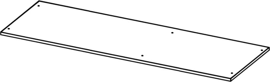 | 15 Drawer bottom panel x1  | |
| 16 Right back panel x1  | |||
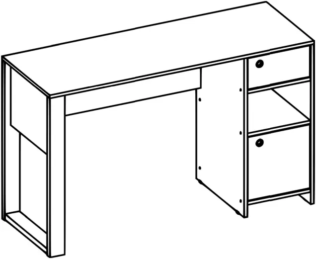
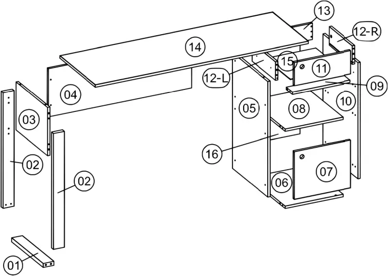
MAIN PARTS LAYOUT (FOR REFERENCE):
LIST OF INCLUDED HARDWARE
PART | QTY | ITEM | |
| A | 12 | Bolt | |
B | 12 | M4x50 | |
| C | 24 | M3.5×12 | |
D | 2 | M4x30 | |
| E | 12 | Cam lock |  |
F | 4 | Plastic foot 15x25mm |  |
| G | 2 | Plastic foot 43x24x7mm |  |
H | 6 | Metal bracket |  |
| I | 1 | Magnet |  |
J | 28 | Wooden dowel M6x30 | |
| K | 2 | Metal pin | |
L | 32 | Nail 10mm | |
| M | 1 | Cable management (grommet) |  |
N | 2 | Handle |  |
| O | 1 | Metal plate 25x15mm | |
P | 2 | Drawer slider | |
| Q | 20 | Self-adhesive sticker |
TOOLS THAT ARE REQUIRED (But not included)
| Phillips Screwdriver | Mallet |
Hammer  |
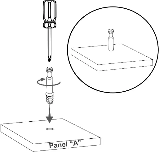
![]() This unit uses cam bolts and locks. The following explains how to use them. This is not an assembly step; it is a guide for when you are actually doing the assembly using this kind of hardware.
This unit uses cam bolts and locks. The following explains how to use them. This is not an assembly step; it is a guide for when you are actually doing the assembly using this kind of hardware.
Cam Lock | |
| 1. Screw the bolt into the corresponding hole on panel “A”.
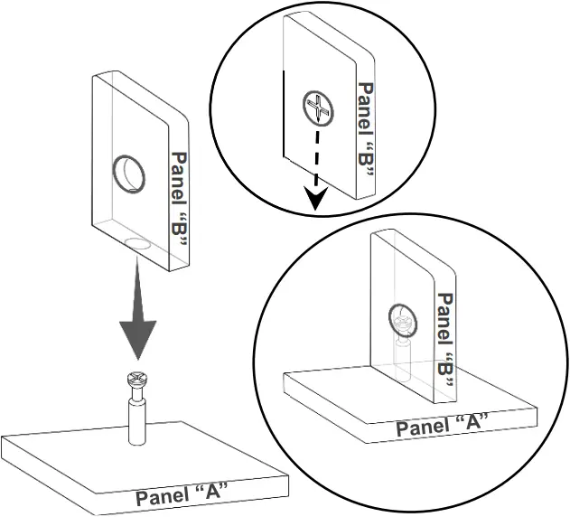
| 2. Join panel “B” to panel “A”. If panel “B” comes with the cam lock pre-installed, make sure it is aligned to receive the bolt’s head (refer to point 3). There might be a very small gap between the panels which is normal.
|
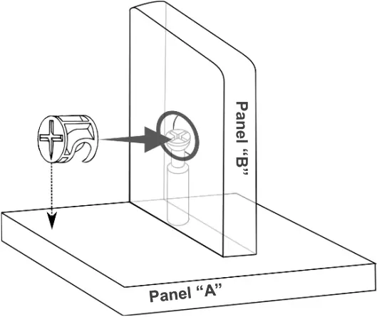
| 3. Insert the cam lock on panel “B” making sure it goes aligned to receive the bolt’s head. Alignment: The cross points towards the panel “A” with the bolt.
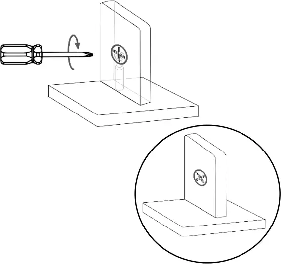
| 4. Turn the cam lock clockwise. This will lock the parts together and will close any gaps.
|
BEFORE YOU START THE ASSEMBLY, PLEASE READ THE FOLLOWING TIPS AND WARNINGS.
 ❶ Do a quick inventory to make sure the package contains all the parts and hardware listed in the assembly instructions. | 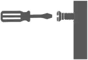 ❼ To avoid misalignments, always leave the screws loose and tighten them until all pieces are positioned correctly. ❼ To avoid misalignments, always leave the screws loose and tighten them until all pieces are positioned correctly. |
 ❷ Missing, damaged and defective parts can be replaced at no cost to you. Please refer to the last pages on this manual. ❷ Missing, damaged and defective parts can be replaced at no cost to you. Please refer to the last pages on this manual. | 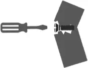 ❽ Do not overtighten or force the screws as they might break, strip, damage the threads of the holes or get stuck inside the part. ❽ Do not overtighten or force the screws as they might break, strip, damage the threads of the holes or get stuck inside the part. |
 ❸ The replacement parts service is limited to the 48 contiguous United States. If you reside in Alaska, Hawaii, Puerto Rico, U.S. territories or other countries, please contact the supplier from where the unit was purchased. ❸ The replacement parts service is limited to the 48 contiguous United States. If you reside in Alaska, Hawaii, Puerto Rico, U.S. territories or other countries, please contact the supplier from where the unit was purchased. | ❾ Sometimes the laminate might cover partially or entirely the hole on a panel. If there is no visible hole for the screw, pass and press the tip of your finger over the area where the hole should be located to feel the indentation, and once found, carefully pierce the laminate to reveal the hole underneath.
|
 ❹ If during assembly you find an issue or need clarification, please contact our Customer Service for assistance. Please refer to the last pages on this manual. ❹ If during assembly you find an issue or need clarification, please contact our Customer Service for assistance. Please refer to the last pages on this manual. | |
 ❺ On each step read the instructions and analyze the illustrations thoroughly before proceeding to do the assembly. ❺ On each step read the instructions and analyze the illustrations thoroughly before proceeding to do the assembly. | ❿ If the hole seems too small for the screw, first make sure you are using the correct size of screw and that it’s been installed in the correct hole. If the hole still appears to be too small, carefully pierce the laminate to reveal the hole’s actual size.
|
 ❻ Make sure you understand which hardware will be used on each step. Using the wrong size of screw, bolt or pin might strip the threads or cause damage to the part in which it is being used. ❻ Make sure you understand which hardware will be used on each step. Using the wrong size of screw, bolt or pin might strip the threads or cause damage to the part in which it is being used. |


ASSEMBLY STEPS
STEP 1 | ||
Hardware: | ||
J | Dowel M6x20 | 24 Pcs |
Tools required | ||
 | ||
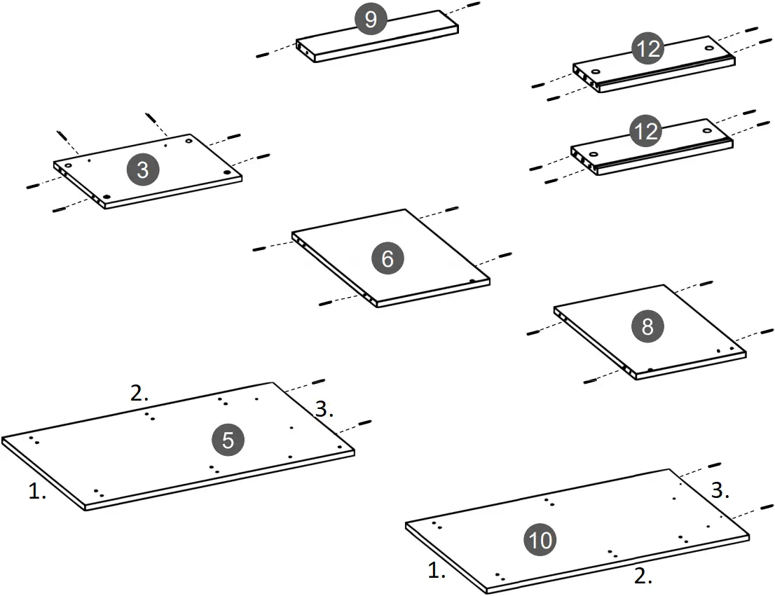
Use a mallet to install the dowels J into the indicated holes on panels 3, 5, 6, 8, 9, 10 and 12.
- (Bottom)
- (Front)
- (Top)
STEP 2 | ||
Hardware: | ||
A | Bolt | 12 Pcs |
Tools required | ||
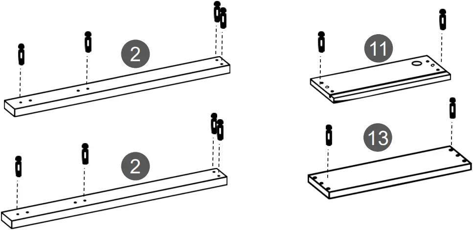
Install the bolts A into the indicated holes on panels 2, 11 and 13.
STEP 3 | ||
Hardware: | ||
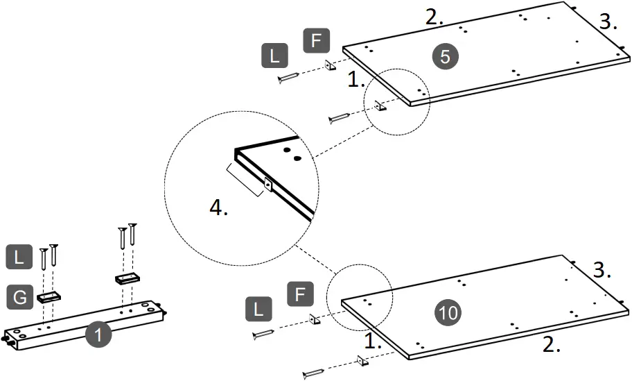
F | Foot | 4 Pcs |
| G | Foot | 2 Pcs |
L | Nail | 8 Pcs |
Tools required | ||
| ||
Use nails L to install:
- The feet F to the bottom of panels 5 and 10.
- The feet G to the base 1.
- (Bottom)
- (Front)
- (Top)
- Install F at approximately 2” from each end on 5 and 10
STEP 4 | ||
Hardware: | ||
P |
| 2 Pcs |
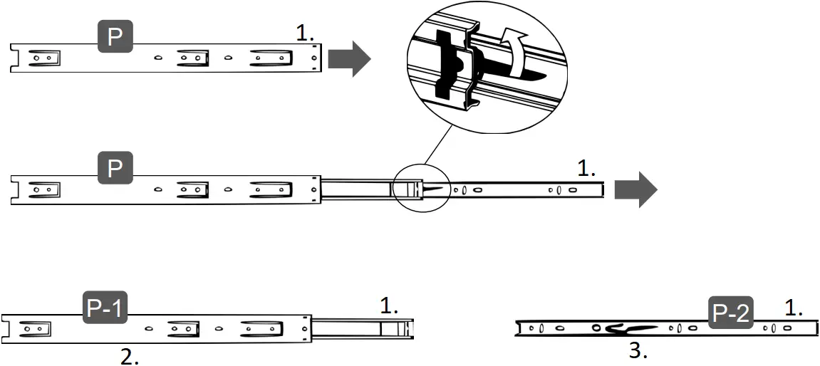
- Grab the sliders P and extend them completely towards the RIGHT.
- In between the smaller piece and the middle piece there is a black plastic lever sticking out, with the tip of your thumb press the lever UP and at the same time pull out the smaller piece away from the rest.
- The slider will now be split into piece P-1 (big) and P-2 (small).
- (Front)
- The “Big” pieces P-1 will be used on big panels 5 and 10.
- The “Small” pieces P-2 will be used on small panels 12.
STEP 5 | ||
Hardware: | ||
C | M3.5×12 | 8 Pcs |
| P-1 | Big | 2 Pcs |
P-2 | Small | 2 Pcs |
Tools required | ||
Important notes for this step:
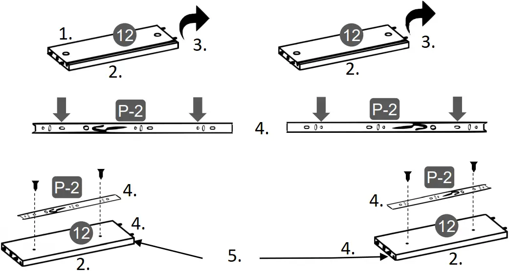
- Both panels 12 are exactly the same, however, one will be used as RIGHT side and the other as LEFT side.
- All the pieces of sliders P-1 and P-2 have a front end that will need to face towards the front of the panels.
- Flip the panels 12 and assemble to them the small sliders P-2 with screws C, but oriented opposite on each panel. Make sure that the grooves on the other side are located at the BOTTOM.
- (Top)
- (Bottom)
- Flip
- (Front)
- The grooves go at the bottom
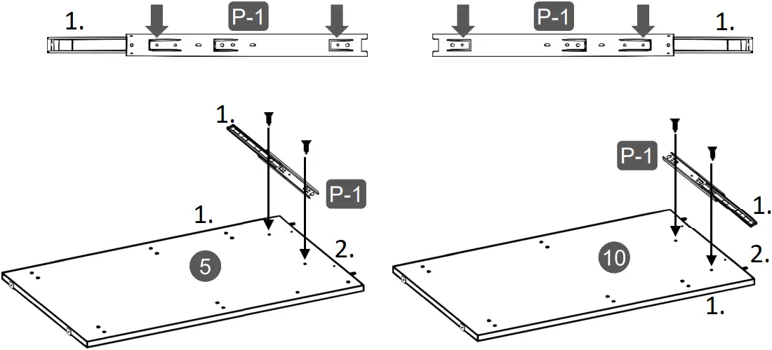
- Assemble the big sliders P1 to the panels 5 and 10 on the top sets of holes with screws C. Attach first the back hole (2nd from the back end), then open the slider slowly until you are able to see the front hole (1st from the front end). You might need to slide away the piece with the ball bearings to clear the view of the hole.
- (Front)
- (Top)
STEP 6 | ||
Hardware: | ||
C | M3.5×12 | 6 Pcs |
| H | Bracket | 6 Pcs |
Tools required | ||
Install the brackets H to panels 3, 5 and 10 with screws C in the indicated locations. 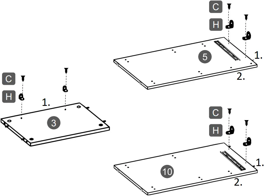
- (Top)
- (Front)
STEP 7 | ||
Hardware: | ||
C | M3.5×12 | 4 Pcs |
| I | Magnet | 1 Pc |
K | Metal pin | 2 Pcs |
| N | Handle | 2 Pcs |
O | Plate | 1 Pc |
Tools required | ||
| ||
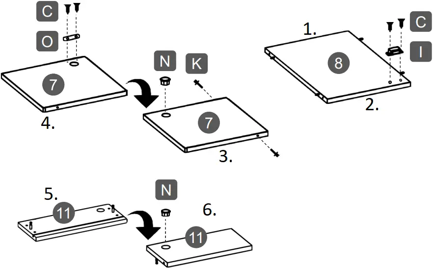
- Install the metal plate O to the door 7 with screws C.
- Install the metal pins K to the door 7.
- Install the handles N to the panels 7 and 11.
- Install the magnet I to panel 8 with screws C oriented towards the front of the panel.
- (Back)
- (Front)
- (Outside face)
- (Inside face)
- (Back face)
- (Front face)
STEP 8 | ||
Hardware: | ||
B | M4x50 | 1 Pc |
Tools required | ||
Assemble panel 9 to panel 10 with screws B as shown. The screw goes through panel 10 and into panel 9.
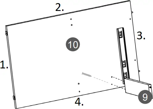
- (Bottom)
- (Back)
- (Top)
- (Front)
STEP 9 | ||
Hardware: | ||
B | M4x50 | 2 Pcs |
Tools required | ||
Assemble panel 8 to panel 10 with screws B as shown. The screws go through panel 10 and into panel 8.
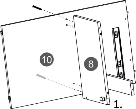
- (Front)
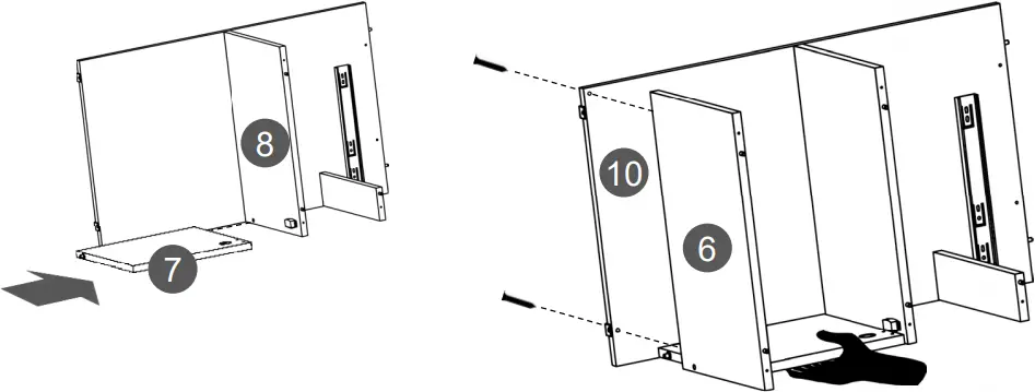
STEP 10 | ||
Requires of 2 persons | ||
Hardware: | ||
B | M4x50 | 2 Pcs |
Tools required | ||

With the help of another person, attach the door 7 to panel 8 by inserting its metal pin into the corresponding hole, and while the other person holds the panel, assemble panel 6 to panel 10 with screws B making sure the pin from 7 inserts into the hole on 6.
FIRST: THEN:
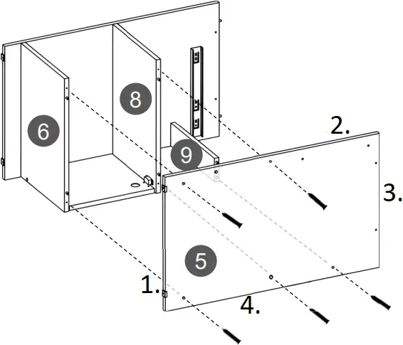
STEP 11 | ||
Hardware: | ||
B | M4x50 | 5 Pcs |
Tools required | ||
Assemble panel 5 to panels 6, 8 and 9 with screws B as shown.
- (Bottom)
- (Front)
- (Top)
- (Back)
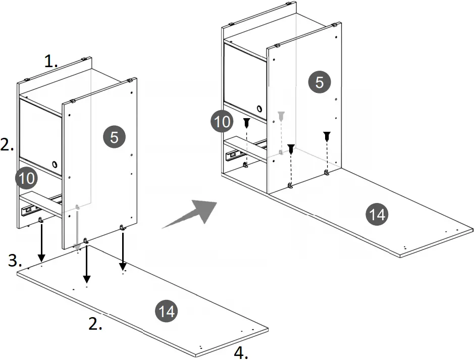
STEP 12 | ||
Requires of 2 persons | ||
Hardware: | ||
C | M3.5×12 | 4 Pcs |
Tools required | ||
- Place the tabletop 14 upside-down over a clean blanket to protect its finish.
- With the help of another person, place the cabinet section built in step 11 over the tabletop 14 making the brackets H coincide with the pre-drilled holes and secure panels 5 and 10 to 14 with screws C as shown.
- (Bottom)
- (Front)
- (Right)
- (Left)
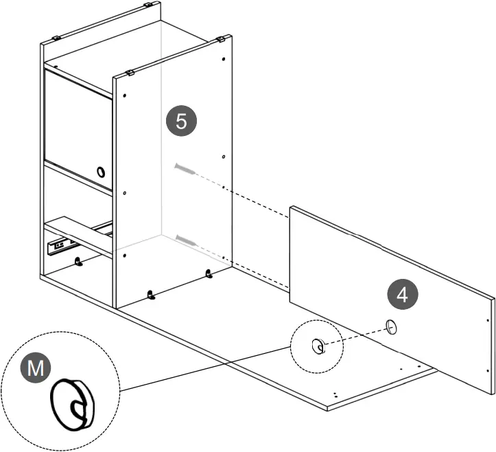
STEP 13 | ||
Hardware: | ||
B | M4x50 | 2 Pcs |
| M | | 1 Pc |
Tools required | ||
| ||
Insert the cable management (grommet) M into panel 4, then assemble it to panel 5 with screws B as shown.
STEP 14 | ||
Hardware: | ||
E | Cam lock | 8 Pcs |
| Q |  Sticker | 4 Pcs |
Tools required | ||
- Join the supports 2 to the base 1 and to the left panel 3. Make sure the base 1 will have its smooth surface facing UP.
- Insert the cam locks E into panels 1 and 3 and turn them to lock the pieces as explained in page 4.
- Cover the cam locks E on panel 3 with the stickers Q.
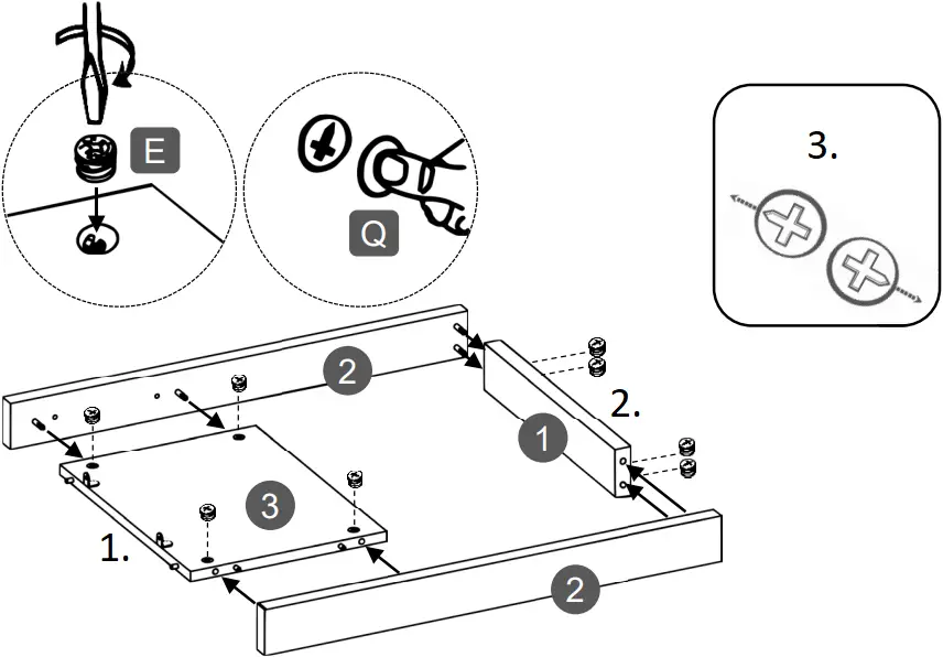
- (Top)
- (Bottom)
- Cam locks alignment on 1 and 3
STEP 15 | ||
Requires of 2 persons | ||
Hardware: | ||
C | M3.5×12 | 2 Pcs |
| D | M4x30 | 2 Pcs |
Tools required | ||
- With the help of another person, place the leg structure built in step 14 over the tabletop 14 making sure that:
a) The brackets H on panel 3 coincide with the pre-drilled holes on 14.
b) The surface with cam locks on panel 3 faces towards the inside. - Secure the brackets H to panel 14 with screws C.
- Secure the support 2 to panel 4 with screws D as shown.
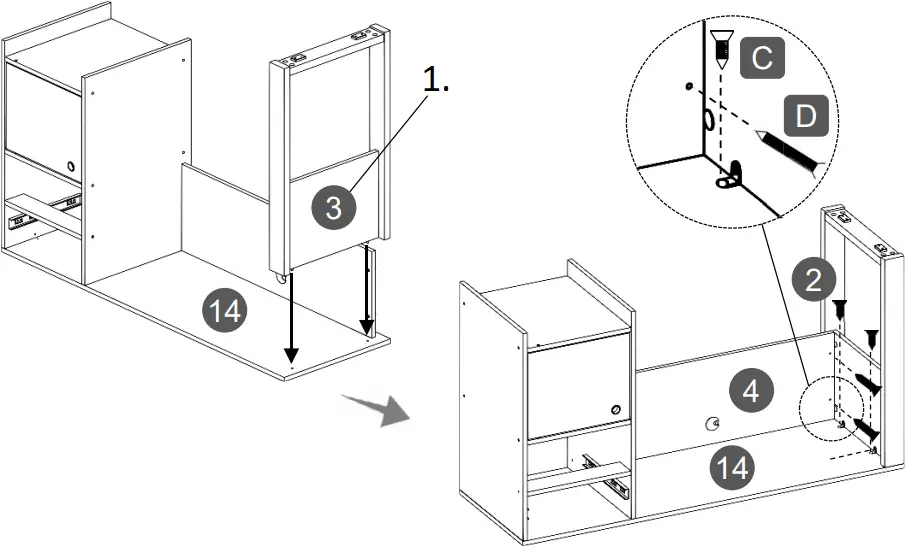
- Cam locks on 3 go facing towards the inside
STEP 16 | ||
Requires of 2 persons | ||
Hardware: | ||
| L | Nail | Min 12 Pcs |
Tools required | ||
| ||
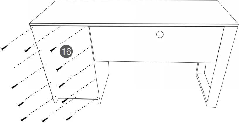
With the help of another person, bring the unit upright, then place the back panel 16 centered over the back of the cabinet, and secure it with a minimum of 12 nails L as shown.
IMPORTANT: Try to nail into the center of the boards and as straight as possible to avoid the nails entering too close to the edges or slanted as the wood might bulge or split.
STEP 17 | ||
Hardware: | ||
E | Cam lock | 2 Pcs |
| Q | Sticker | 2 Pcs |
Tools required | ||
Important notes for this step:
For the drawer, you will use both panels 12, but one will go as the RIGHT side and the other as the LEFT side, so make sure that the sliders P2 on them are facing the opposite direction as it was instructed in Step 5 on page 8.
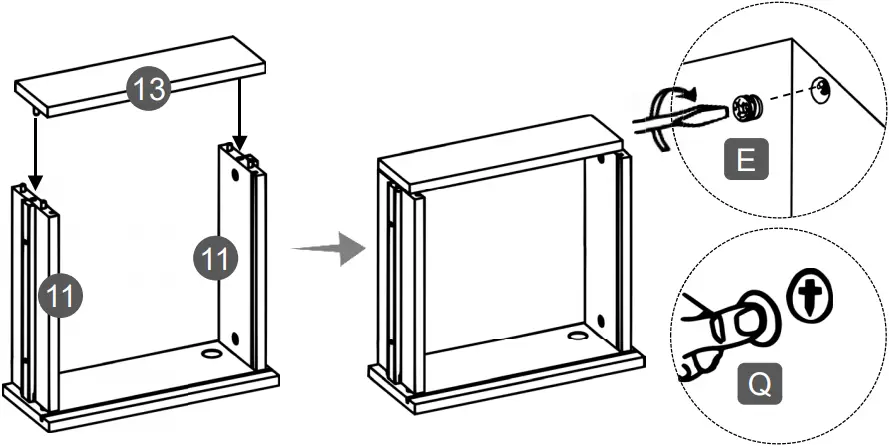
- Assemble the panels 12 to the drawer front panel 11 on their respective sides with cam locks E as shown and as explained in page 4.
- Cover the cam locks with Q.
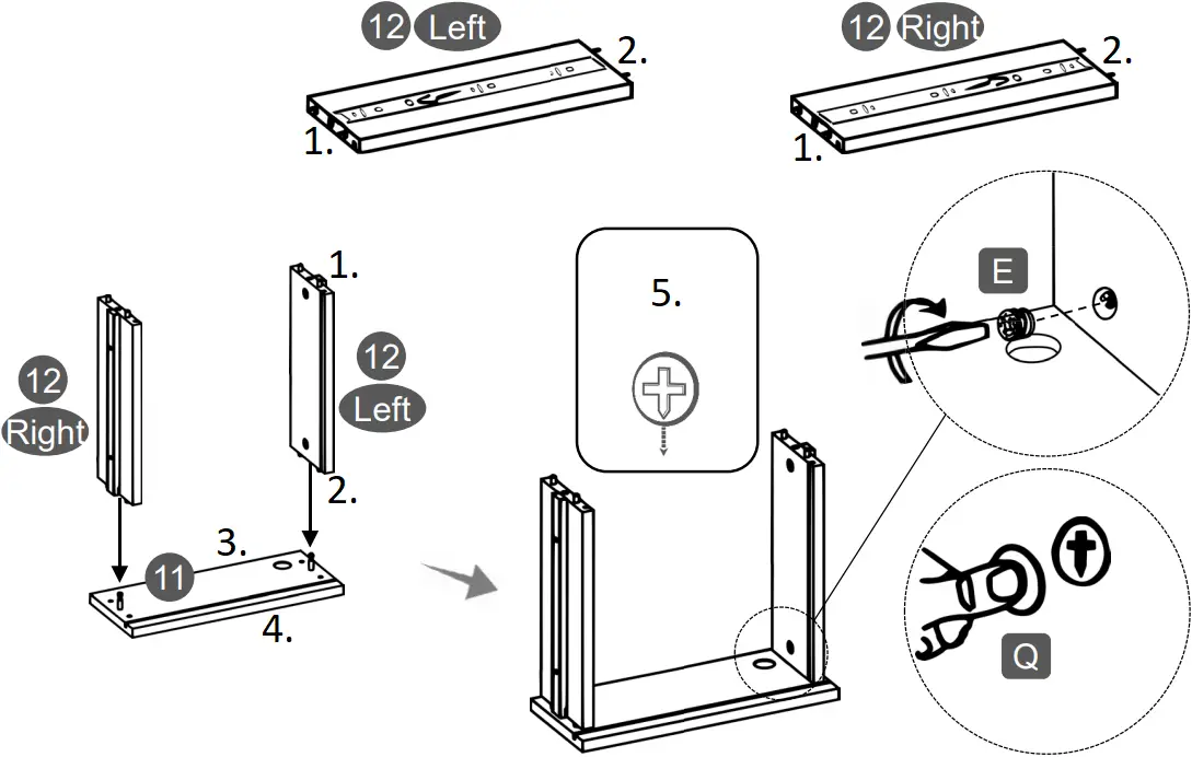
- (Front)
- (Back)
- (Top)
- (Bottom)
- Cam locks alignment on 12
STEP 18 | ||
Hardware: | ||
E | Cam lock | 2 Pcs |
| Q | Sticker | 2 Pcs |
Tools required | ||
Assemble the drawer back panel 13 to the side panels 12 with cam locks E as shown and as explained in page 4, then cover the cam locks with Q.
STEP 19 | ||
Hardware: | ||
L | Nail | Min 2 Pcs |
Tools required | ||
| ||
- Slide the drawer bottom panel 15 through the grooves of panels 12 and into the groove of panel 11.
- Secure the bottom panel 15 at the back with at least 2 nails L.
IMPORTANT: Try to nail into the center of the boards and as straight as possible to avoid the nails entering too close to the edges or slanted as the wood might bulge or split.
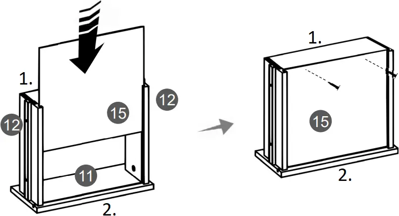
- (Back)
- (Front)
STEP 20 | ||
Hardware: | ||
Q | Sticker | 12 Pcs |
- On the main unit first make sure that on the sliders P1 the piece with the ball bearing is all the way to the front. If they are not, slide them with the tip of your finger towards the front.
- Install the drawer by engaging its sliders P2 through the black plastic guide and the bearings of P1, and pushing slowly inside.
- Cover all visible screw holes and cam locks with Q.
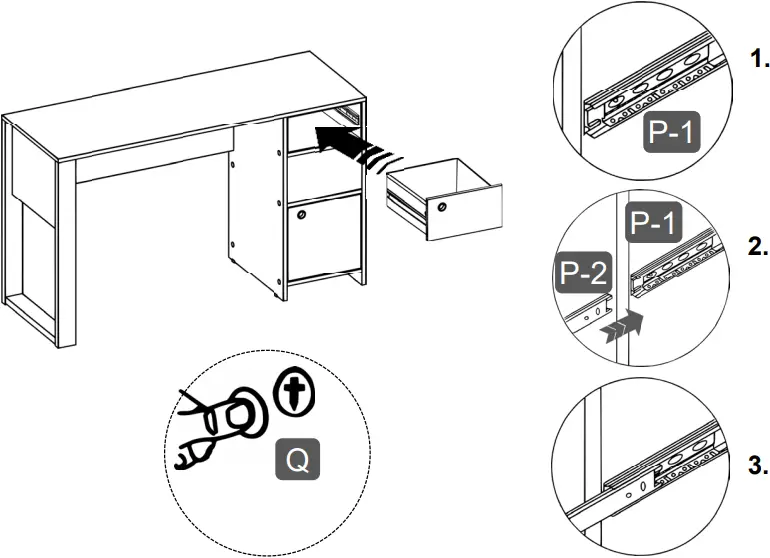
1. Make sure the piece with the ball bearings is all the way to the front
2. The slider P2 must go through the plastic guide and engage into the ball bearing piece of P1
3. Push in very slowly.
![]() ALL DONE!
ALL DONE!
Give yourself a nice pat on the back, you did a great job!
Enjoy your new unit.
CARE, MAINTENANCE AND SAFETY WARNINGS:
WEIGHT LIMITS
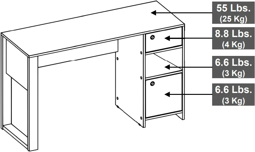
- Do not exceed the indicated weight limits.
- Do not expose the surfaces to direct sunlight or to extreme environmental conditions.
- Clean the surfaces preferable with a clean cloth damped in a solution of mild soap and water, then dry with a clean towel.
- Do not use solvents or abrasive materials to clean the unit.
- If you decide to use a cleaning agent, test first on an area hidden from view such as underneath the tabletop.
- Do not sit on the unit or lean against it.
- Do not allow small children to play under or over the unit.
- Do not allow small children to reach inside the drawers or compartments without your supervision.
- Do not pull, push or drag the unit to move it for more than 1 feet. The unit must be lifted by at least 2 persons when moving in the same or adjacent rooms.
- Before moving the unit, make sure to secure or remove any object that is heavy or might fall off.
- When lifting the unit, use both hands and bend your knees, not your backs.
- When transporting the unit to places far away, protect and secure the unit to avoid damage in transit.
- Shall any part of the unit become defective during the warranty period, replacement parts might be available to you at no charge. Please refer to the last pages on this manual.
- The warranty does not extend to regular wear and tear, nor the manufacturer assumes liability for damages or consequences due to accidents, incorrect assembly, negligence, improper use, modifications, or not heeding the above warnings.
TECHNI MOBILI DESK WARRANTY
DESKS/LAPTOP CARTS/FILE CABINETS: LIMITED 5-YEAR WARRANTY
RTA Products, LLC warrants to the Original Purchaser who acquired a new product from RTA Products or its authorized resellers that this product will be free from defects in its workmanship and materials, under normal use and service conditions, as described herein. “Defects” as used in this warranty, is defined as any imperfections that impair the use of the furniture or product. RTA Products LLC will replace any defective part, at its discretion, and without charge to the original purchaser other than the freight from the end consumer to RTA Products.
Replacement parts can only be supplied if parts are available. Items out of production may be unavailable. This warranty will be effective for the applicable time period beginning the date of purchase on your original sales receipt. RTA product’s obligation under this warranty is limited to repairing or replacing products or parts as provided herein. This product has been designed for and is intended for office and home-office use only. This warranty is Original Purchaser’s sole remedy for product defects, and this warranty does not extend to any product, or damage to any product, caused by or attributed to abuse or misuse, products used for commercial or rental purposes, use modifications of, or attachments to the product, and products or parts not used, maintained, or extended hereunder is in lieu of any and all other warranties, express or implied, including without limitations any implied warranty or merchantability or of fitness for a particular purpose. Please note, all desks made with PVC Laminate surface should not be exposed to direct sunlight, as it may damage the material. Damage of this nature is not covered under this warranty.
RTA Products will not be responsible for indirect, special, incidental or consequential damages. This warranty is limited to merchandise purchased in the Continental United States, excludes AK, HI and PR. Some States do not allow the exclusion or limitation of incidental or consequential damages, so the above limitations or exclusions may not apply to you. This warranty gives you specific legal rights. You may also have other rights that may vary from state to state.
RTA Products will advise you of the procedure to follow in making warranty claims. The following are the procedures for warranty claims:
a. Call us Monday - Friday, from 9am-5pm (Eastern Time) at (866) 782-5520 to explain the defect and give your name, address and phone number. Please have ready the model number of our product, date and place of purchase. You can also write to us by e-mail to [email protected] and include the same information.
b. If we determine that replacement will remedy the situation, and in order to determine the extent or the cause of the defect, purchaser will need to send the part in question at purchaser’s expense. Once we receive the part, we will examine it and determine whether the claim is valid (or not), and then proceed to send the replacement. We will ship the replacement at our expense.
FOR SEVERAL HELP OPTIONS
INCLUDING REPLACEMENT PARTS ORDERS
VISIT: WWW.TECHNIMOBILI.COM
![]() CLICK ON SUPPORT TAB
CLICK ON SUPPORT TAB

Scan QR Code to order replacement parts
OR EMAIL US: [email protected]


