HMT-2250/1800-6T Quick Installation Guide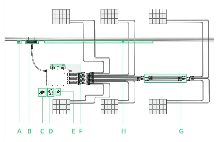
Accessories
| Item | Description |
| A | 3P-AC Trunk End Cap |
| B | 3P-AC Trunk Connector |
| C | 3P-AC Trunk Port Disconnect Tool |
| D | 3P-AC Trunk Connector Unlock Tool |
| E | 3P-AC Trunk Port Cap |
| F | DC Extension Cable,1m |
| G | 3P-AC Trunk Cable, 12/10 AWG Cable |
| H | M8*25 screws (Prepared by the installer) |
*Note: All accessories above are not included in the package and should be purchased separately.
Installation Steps
The order of Step 1 and Step 2 can be reversed according to your planned needs.
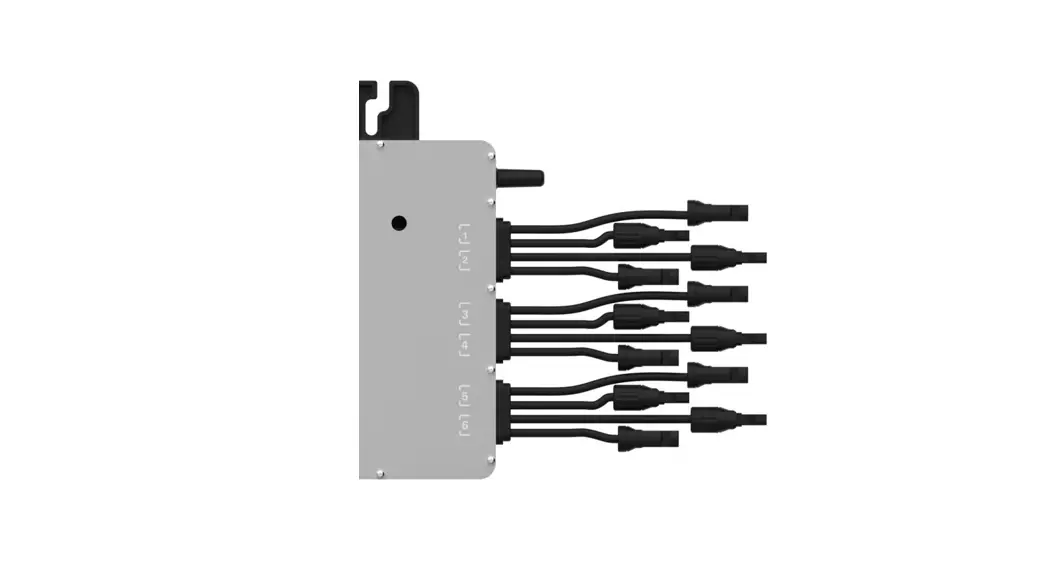
Step 1. Plan and install the Microinverter
A ) Mark the position of each microinverter on the rail, according to the PV module layout.
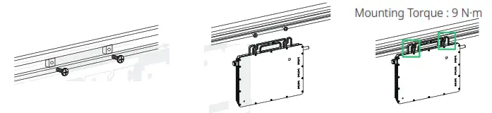
B ) Fix the screw on the rail.
C ) Hang the microinverter on the screws, and tighten the screws. The silver cover side of the microinverter should be facing the panel.
Note:
- Install the microinverter and all DC connections under the PV module to avoid direct sunlight, rain exposure, snow buildup, UV, etc.
- Leave at least 2 cm of space around the microinverter enclosure to ensure ventilation and heat dissipation.
- Mounting torque of the 8 mm screw should be 9 N·m. Please do not over-torque.
Step 2. Plan and Build the 3P-AC Trunk Cable
3P-AC Trunk Cable is used to connect the microinverter to distribution box.
A ) Determine how many microinverters you plan to install on each AC branch and prepare AC Trunk Connectors accordingly.
B ) Take out segments of AC Trunk Cable as you need to make AC branch.
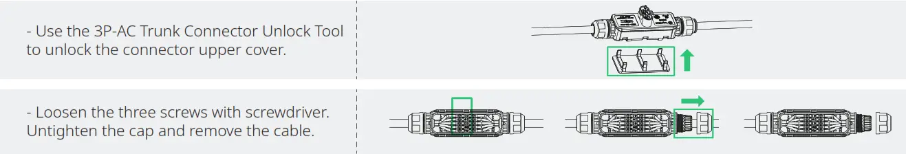
- Disassemble the AC Trunk Connector and remove the cable.

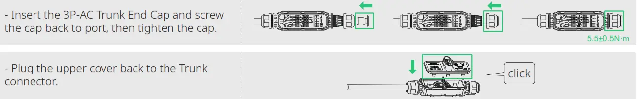
- Install the 3P-AC Trunk End Cap at one side of 3P-AC Trunk Cable (The end of 3P-AC Trunk Cable)

- Install AC end cable on the other side of 3P-AC Trunk Cable (connected to the distribution box)


| – Prepare a segment of AC cable with suitable lengthto connect to the distribution box, with stripping requirements fulfilled. | 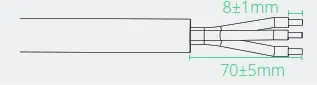 |
| – Insert the cable into the cap in a way that theL1, L2, L3, PE and N lines are in corresponding slots. | 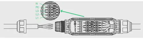 |
| – Tighten the screws: and tighten the cap back to the port. | 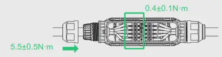 |
| – Plug the upper cover back to the Trunk connector. | 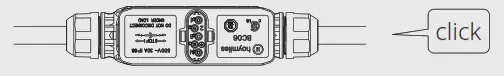 |
Note:
- Tightening torque of the cap: 5.5±0.5 N·m. Please do not over-torque.
- Torque of locking screw: 0.4±0.1 N·m.
- Do not damage the sealing ring in the 3P-AC Trunk Connector during disassembly and assembly.
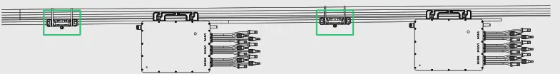
C ) Repeat the above steps to make all the 3P-AC Trunk Cables you need, then lay out the cable on the rail in the suitable position so that the microinverters can be connected to the Trunk connectors.
D ) Attach the 3P-AC Trunk Cable to the mounting rail and fix the cable with tie wraps. Step 3. Complete the AC Connection
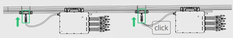
A ) Push the AC Sub Connector from microinverter to the 3P-AC Trunk Connector until it clicks.
 B ) Connect the AC end cable to the distribution box, and wire it to the local grid network.
C ) Please plug the 3P-AC Trunk Port Cap in any vacant AC Trunk Port to make it water and dust-proof.
 B ) Connect the AC end cable to the distribution box, and wire it to the local grid network.
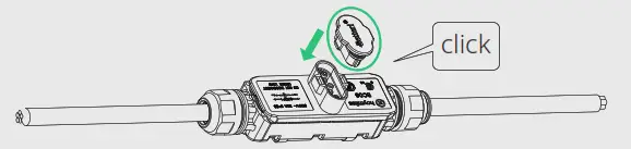
Note:
- Make sure that the 3P-AC Trunk Connectors are kept away from any water-channeling surface.
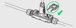
- In case you need to remove the microinverter AC cable from 3P-AC Trunk Connector, please use the 3P-AC Trunk Port Disconnect Tool and insert the tool into the side of AC Sub Connector to complete the removal.
Step 4. Create an Installation Map
A ) Peel the removable serial number label from each microinverter.
B ) Affix the serial number label to the respective location on the installation map (please refer to the appendix).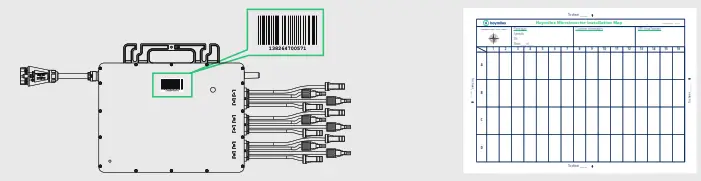
Step 5. Connect PV Modules
A ) Mount the PV modules above the microinverter.
B ) Connect the PV modules’ DC cables to the DC input side of the microinverter.
Note: Please use DC extension cables.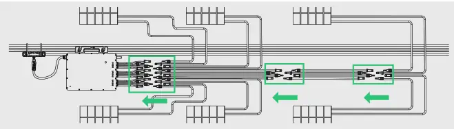
Step 6. Energize the System
A) Turn on the AC breaker for the branch circuit.
B) Turn on the main AC breaker for the house. Your system will start to generate power in about two minutes.
Step 7. Set up Monitoring System
Please refer to the DTU User Manual or DTU Quick Install Guide, and Quick Installation Guide for S-miles Cloud to install the DTU and set up monitoring system.
Product information is subject to change without notice. (Please download reference manuals at www.hoymiles.com).
Region: Global AP040390 REV1.1 © 2020 Hoymiles Power Electronics Inc. All rights reserved.


