Unitra WS303 Stereo Integrated Amplifier User Manual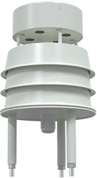
INTRODUCTION
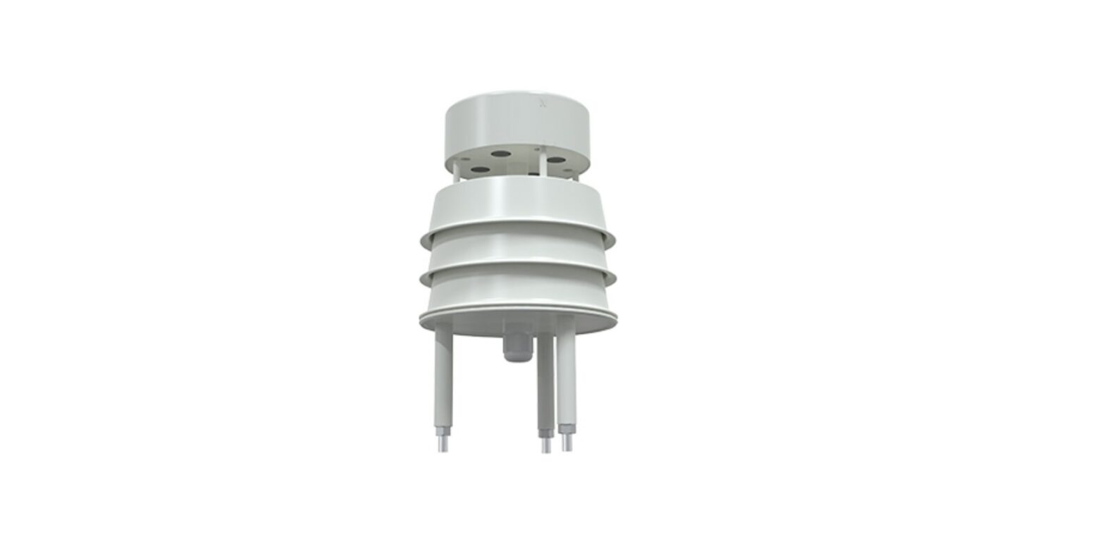
WS303U small ultrasonic wind speed and direction sensor is a wind speed and direction measuring instrument based on the ultrasonic principle. It uses the acoustic pulse sent to measure the phase difference of the receiving end to calculate the wind speed and direction. The sensor can measure the instantaneous value of wind speed and direction at the same time. It is widely used in the fields of meteorology, ocean, environment, airport, port, laboratory, industry, agriculture and transportation. The equipment with built-in electronic compass no longer has the requirement of orientation during installation. It only needs to ensure the horizontal installation. The whole machine shell is made of high-quality ABS material, which has the characteristics of light weight, no moving parts, strong and durable.
FEATURES
- No angle limit, wind speed and direction data can be measured at the same time
- No moving parts, small wear and long service life
- The random error identification technology can ensure the low discrete error of measurement and make the output more stable under strong wind
- Using ABS engineering plastic shell, the design is light, portable, easy to install and disassemble
- Analog signal output, 4 ~ 20mA, 0 ~ 5V, 0 ~ 10V optional
- 485 communication interface, standard Modbus RTU communication protocol, communication address and baud rate can be set, and the farthest communication distance is 2000 meters
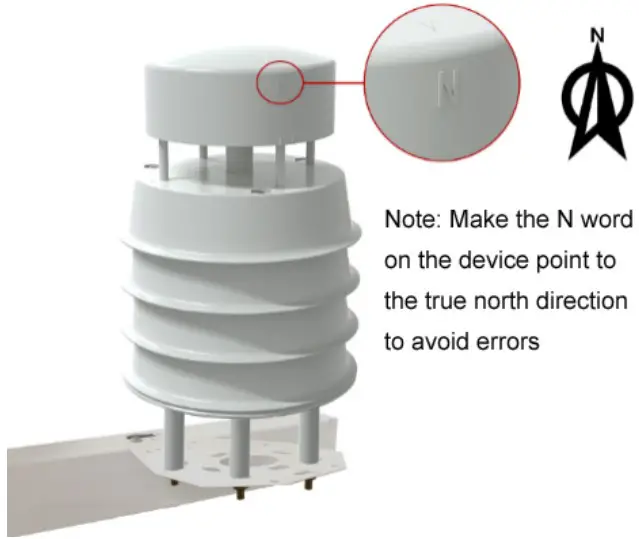
- The equipment with built-in electronic compass can be installed horizontally without direction requirement
- No maintenance and field calibration required
WORKING PRINCIPLE
Ultrasonic wind measurement is an application of ultrasonic detection technology in the gas medium. It uses the influence of air flow (wind) on the propagation speed of ultrasonic in the air to measure the wind speed. Compared with the conventional wind cup or rotor anemometer, the most important feature of this method is that the whole wind measuring system has no mechanical rotating parts and belongs to non inertial measurement, so it can accurately measure the high frequency component of gust pulsation in natural wind. Ultrasonic wind speed and direction transmitter uses four ultrasonic probes to send and receive ultrasonic waves in two-dimensional plane circularly. The principle that ultrasonic waves are affected by wind speed and thus increase or decrease is used to measure wind speed and direction.
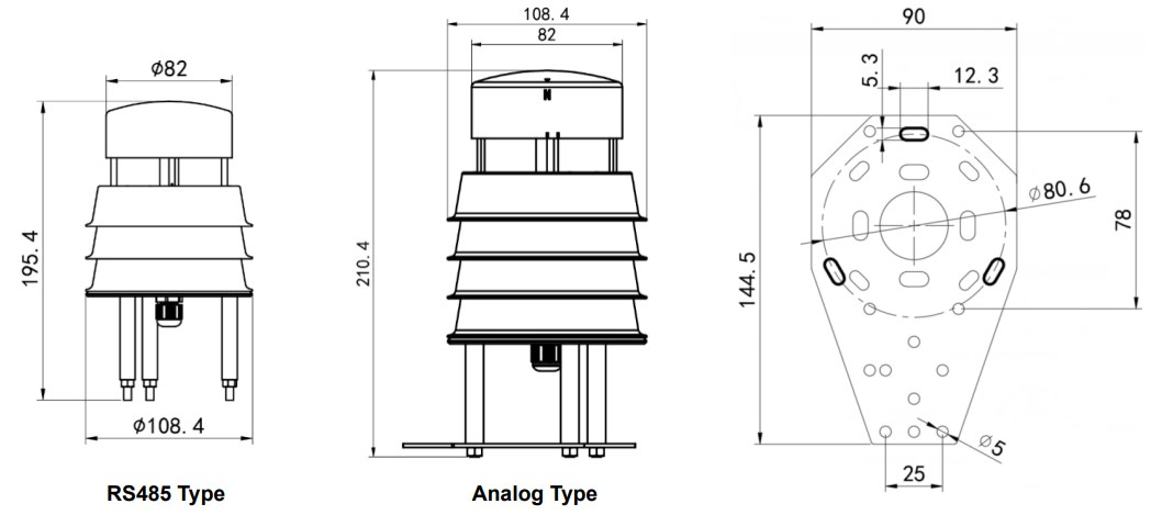
APPEARANCE SKETCH
TECHNICAL SPECIFICATION
| Supply voltage | 10-30V DC (0-10V output is powered by 24 V) | |
| Power consumption | 485:0.12W4~20mA/0~5V/0~10V:1.2W | |
| Range | Wind speed | 0 ~ 40m / S (customizable),0.5m starting wind speed |
| Wind direction | 0~360° | |
| Accuracy | Wind speed | ±0.5+2%FS |
| Wind direction | ±3° | |
| Resolution | Wind speed | 0.01 m/s |
| Wind direction | 1° | |
| Working environment | -40~80℃,0~95%RH | |
| Wind resistance | 75 m/s | |
| Response time | 1S | |
| IP grade | 485 type: IP65, analog type: IP54 | |
| Signal output | 485 (Modbus RTU protocol) 4 ~ 20mA current output0 ~ 10V, 0 ~ 5V voltage output | |
| Load ability | Current output | ≤600Ω |
| Voltage output | Output resistance ≤ 250 Ω | |
INSTALLATION INSTRUCTION
- Inspection before equipment installation
Equipment list: 1 sensor equipment Certificate and warranty card One white bracket, two M4 * 10 screws and nuts, and three M5 nuts - Installation method
Beam installation (optional) The installation of the device without electronic compass is shown in the figure below. The device with built-in electronic compass only needs to be installed horizontally
ANALOG OUTPUT
- Interface description
Wide voltage power supply input 10-30V DC power supply. For 0 ~ 10V output equipment, the power supply is 24 vLine color Explain Power brown Power supply positive black Power supply negative Output
yellow Wind speed signal positive white Negative wind speed signal blue Wind direction signal positive green Negative wind direction signal
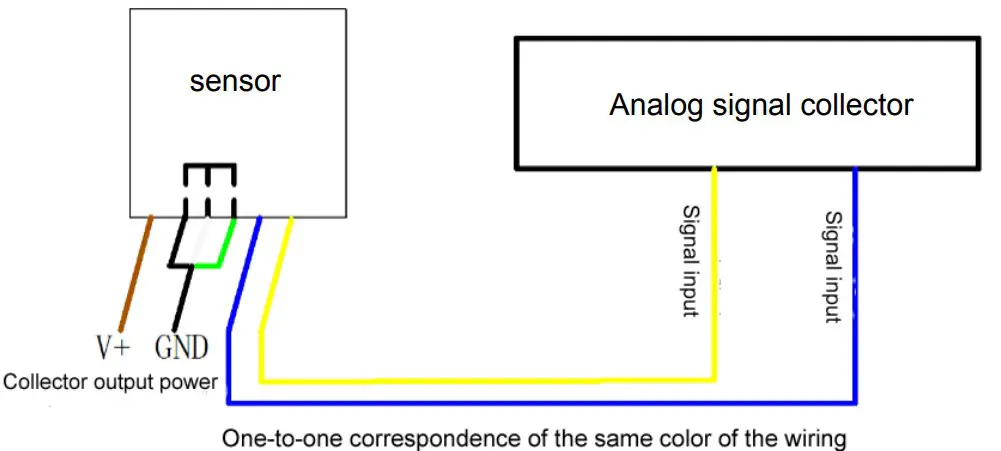
2. Example of connection mode
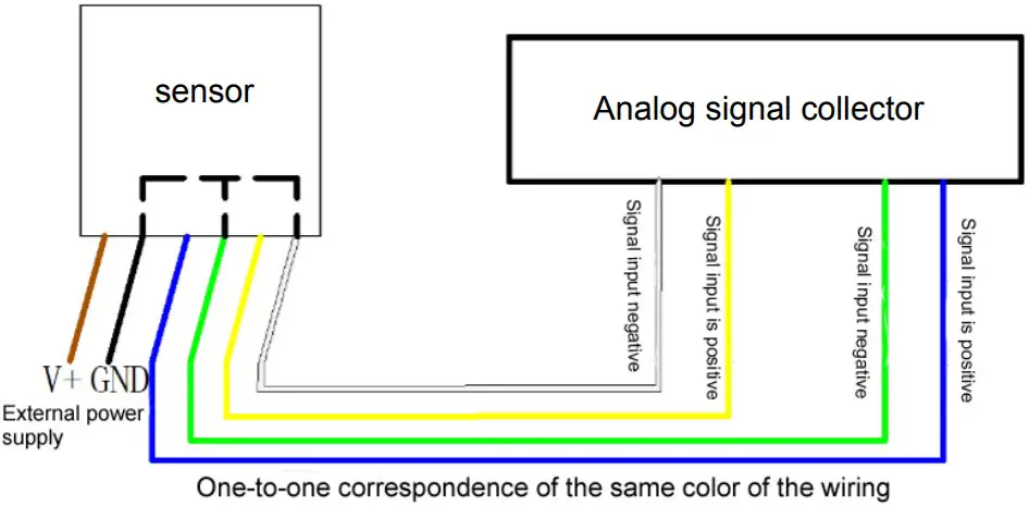
4-wire wiring diagram
3. Computing method
conversion calculation of current mode output signal
The measuring range is 0 ~ 40m / s, 4 ~ 20mA output. When the output signal is 12mA, the current wind speed is calculated. The span of wind speed range is 40m / s, which is expressed by 16mA current signal. 40m / S / 16mA = 2.5m/s/ma, that is, the current changes 1mA, and the wind speed changes 2.5m/s. Then the measured value can be calculated. The measured value 12ma-4ma = 8Ma. 8Ma * 2.5m/s/ma = 20m / S, and the current wind speed = 20m / s.
calculation of voltage mode output signal conversion
The measuring range is 0 ~ 40m / s. take 0-10V output as an example, when the output signal is 5V, the current wind speed is calculated. The span of wind speed range is 40m / s, which is expressed by 10V voltage signal. 40m / S / 10V = 4m / S / V, that is, every 1V change of voltage corresponds to 4m / s change of wind speed. The measured value is 5v-0v = 5V. 5V*4#mmm_s/V=20m/s。 The current wind speed is 20m / s.
RS485 COMMUNICATION OUTPUT TYPE
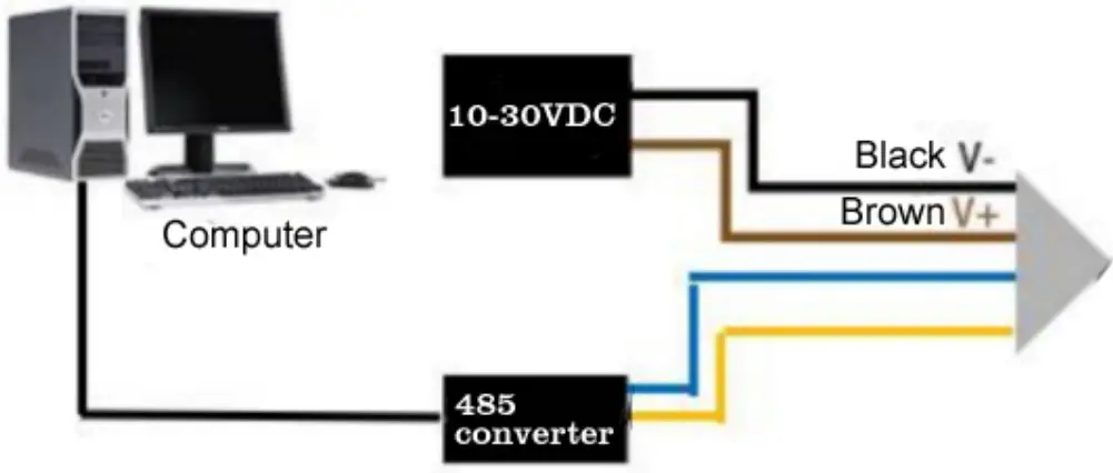
1. Interface description
Wide voltage power supply input 10-30V DC power supply. When connecting 485 signal line, it is noted that the two lines a and B cannot be connected reversely, and the address between multiple devices on the bus cannot conflict.
| Line color | Explain | |
| Power | brown | Positive power supply (10 ~ 30V DC) |
| black | Power supply negative (GND) | |
| Output | yellow | 485-A |
| blue | 485-B |
2. Installation and use of configuration software
Software selection
Open 485 data package, select “debugging software” – “485 parameter configuration software”, find (Parameter configuration tool.exe) and open it.
Equipment connection
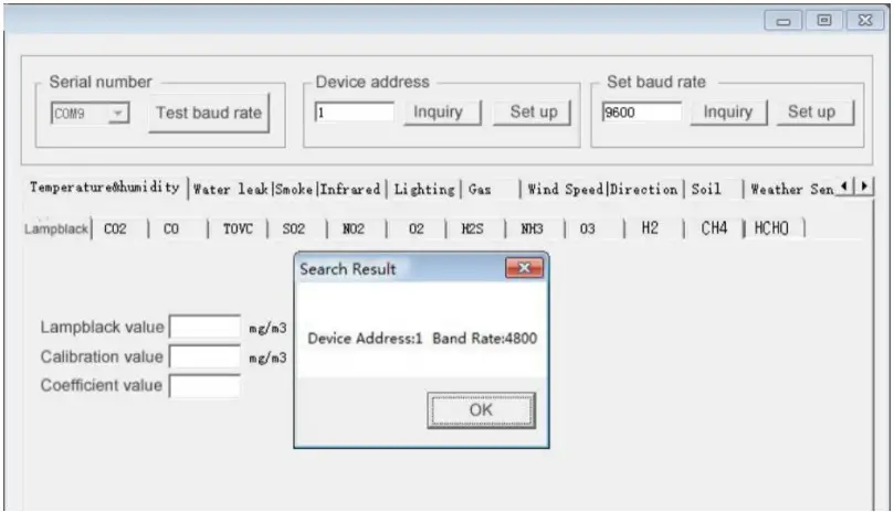
Parameter setting
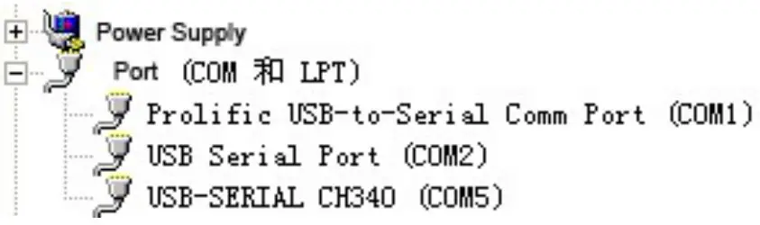
(1) Select the correct COM port (check the COM port in my computer – properties – Device Manager – port). The following figure lists the driver names of several different 485 converters.
(2) After connecting a device separately, power on and click “test baud rate” of the software. The software will test the baud rate and address of the current device. The default baud rate is 4800bit / s and the default address is 0x01.
(3) Modify the address and baud rate according to the need, and query the current function status of the device.
(4) If the test is not successful, please recheck the equipment wiring and 485 driver installation.
Modbus communication protocol
Basic communication parameters
| Coding | 8-bit binary |
| Data bit | 8 bit |
| Parity bit | no |
| Stop bit | 1 digit |
| Error checking | CRC (Redundant Cyclic Code) |
| Baud rate | It can be set by yourself, and the factory default is 4800bit / s |
Data frame format definition
Modbus RTU communication protocol is adopted, and the format is as follows:
Time of initial structure ≥ 4 bytes
Address code = 1 byte
Function code = 1 byte
Data area = n bytes
Error check = 16 bit CRC code Time to end structure ≥ 4 bytes Address code: the address of the transmitter, which is unique in the same communication network (factory default is 0x01).
Function code: instruction function indication issued by the host.
Data area: the data area is the specific communication data, pay attention to the high byte of 16bits data before! CRC code: two byte check code.
Host query frame structure:
| Address code | Function code | Register start address | Register length | CRC_L | CRC_H |
| 1byte | 1byte | 2byte | 2byte | 1byte | 1byte |
Slave response frame structure:
| Address code | Function code | Valid bytes | 1st Data area | 2nd Data area | Data N area | CRC_L | CRC_H |
| 1byte | 1byte | 1byte | 2byte | 2byte | 2byte | 1byte | 1byte |
Register address
| Register address | PLC or configurationaddress | Content | Operation | Definition |
| 0000 H | 40001 (decimal) | Instantaneous wind speed | Read-only | Real time value of wind speed (expanded by 100 times) |
| 0001 H | 40002 (decimal) | wind direction | Read-only | Real time value of wind direction (integer, 0 ° due north, 90 ° due east) |
| 0002 H | 40003 (decimal) | Maximum wind speed | Read-only | Maximum wind speed after power on of equipment (expanded by 100 times) |
| 0003H | 40004 (decimal) | Wind power rating | Read-only | Wind level corresponding to the current wind speed (integer, 0-17) |
| 07D0 H | 42001 (decimal) | Device address | Read-write | 1 ~ 254 (factory default 1) |
| 07D1 H | 42002 (decimal) | Baud rate of equipment | Read-write | 0 for 24001 stands for 48002 for 9600 |
Communication protocol example and explanation
For example: read the real-time value of wind speed and direction of transmitter equipment (address 0x01)
Question frame:
| Address code | Function code | Starting address | Data length | CRC_L | CRC_H |
| 0x01 | 0x03 | 0x00 0x00 | 0x00 0x02 | 0xC4 | 0x0B |
* Response frame:
| Address code | Function code | Returns the number of valid bytes | Real time value of wind speed | Real time value of wind direction | CRC_L | CRC_H |
| 0x01 | 0x03 | 0x04 | 0x00 0x7D | 0x00 0x5A | 0xEA | 0x10 |
Real time wind speed calculation:
Wind speed: 007d (HEX) = 125 = > wind speed = 1.25 m / S
Real time wind direction calculation:
Wind direction: 005a (HEX) = 90 = > wind direction = east wind
For example: read the real-time wind power rating value of the transmitter equipment (address 0x01)
Question frame:
| Address code | Function code | Starting address | Data length | CRC_L | CRC_H |
| 0x01 | 0x03 | 0x00 0x03 | 0x00 0x01 | 0x74 | 0x0A |
* Response frame:
| Address code | Function code | Number of valid bytes | wind power | CRC_L | CRC_H |
| 0x01 | 0x03 | 0x02 | 0x00 0x01 | 0x79 | 0x84 |
Real time wind rating calculation:
Wind power rating: 0001 (hexadecimal) = 1 = > wind power rating = 1
COMMON PROBLEMS AND SOLUTIONS
Device cannot be connected to PLC or computer Possible reasons:
- The computer has multiple COM ports. The selected port is incorrect.
- The device address is wrong, or there are devices with duplicate addresses (factory default is all 0x01).
- Baud rate, check mode, data bit, stop bit error.
- 485 bus is disconnected, or a and B lines are connected reversely.
- If the number of equipment is too much or the wiring is too long, it is necessary to supply power nearby, add 485 intensifier, and increase 120 Ω terminal resistance at the same time.
- USB to 485 driver is not installed or damaged.
- The equipment is damaged.
Fault phenomenon: no output or output error Possible reasons:
- The range corresponding error leads to PLC calculation error. Please refer to the technical indicators in the first part for the range.
- Wrong wiring mode or wrong wiring sequence.
- The power supply voltage is wrong (for 0-10V type, it is 24 V power supply).
- The distance between transmitter and collector is too long, resulting in signal disorder.
- PLC acquisition port is damaged.
- The equipment is damaged.


 Owner Manual")