![]()
Performance Under Pressure
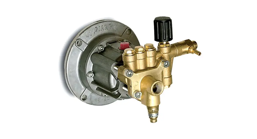
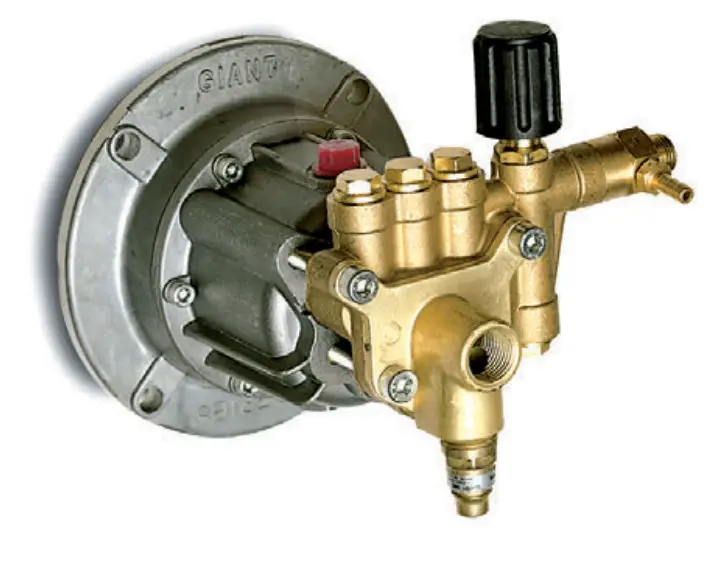
Model – GX Series
Triplex Plunger Pump
Operating Instructions/Repair Instructions Manual
Consumer Pump
Horizontal/Vertical Pump with built-in Thermal
Relief Valve and Siphon Injector
INSTALLATION INSTRUCTIONS
Installation of the Giant Industries Inc., pump is not a complicated procedure, but there are some basic steps common to all pumps. The following information is to be considered as a general outline for installation.
- The pump should be installed flat on a base to a maximum of a 15-degree angle of inclination to ensure optimum lubrication.
- The inlet to the pump should be sized for the flow rate of the pump with no unnecessary restrictions that can cause cavitation. Teflon tape should be used to seal all joints. The maximum inlet fluid temperature is 80°F.
- The discharge plumbing from the pump should be properly sized to the flow rate to prevent line pressure loss to the work area. It is essential to provide a safety bypass valve between the pump and the work area to protect the pump from pressure spikes in the event of a blockage or the use of a shut-off gun.
- Before beginning the operation of your pumping system, remember: Check that the crankcase and seal areas have been properly lubricated per recommended schedules. Do not run the pump dry for extended periods of time. Cavitation will result in severe damage. Always remember to check that all plumbing valves are open and that pumped media can flow freely to the inlet of the pump.
Finally, remember that high-pressure operation in a pump system has many advantages. But, if it is used carelessly and without regard to its potential hazard, it can cause serious injury
IMPORTANT OPERATING CONDITIONS
Failure to comply with any of these conditions invalidates the warranty.
- Your Giant Industries replacement pump comes pre-filled to the proper level with synthetic oil although checking for the proper oil level is advised after removing the red shipping plug and installing your black crankcase breather tube.
- The proper level of oil in the GXH2525 series pump will be just slightly above half full. This pump does not have sight glass so you will need to look into the pump from the top in order to view your oil level. The crankcase oil capacity for your GXH2525 Series Horizontal pumps is 4.1 ounces of oil.
- To change or add oil use only Mobil 1 20W50 Full Synthetic oil
- DO NOT OVERFILL CRANKCASE
- Crankcase oil should be changed after the first 50 hours of operation, then at regular intervals of 100 hours or less depending on the operating conditions of the pump.
- Pump operation must not exceed the rated pressure, volume, or a maximum rate of 3450 RPM’S. Failure to follow these instructions could result in damage to your pressure pump.
- Do not flow Acids’ Alkaline or Abrasive fluids through your GXH2525 series pressure pump for cleaning purposes. These fluids must be applied with the downstream chemical injector provided with your pressure pump.
- Your GXH2525 series pump should be conditioned after every use to help prevent any type of corrosion from building up inside of the part and components of your pump head. We suggest you use Pump Saver Part # 7074403GS, RV Antifreeze or WD-40 to help prevent corrosion inside the brass head of your pump.
- Always winterize your pressure pump before storing your pump in climates that will have any chance of below-freezing temperatures. A small amount of water left in your pump could cause serious damage to your pump and will not be covered under the manufactures warranty.
Specifications
Model GX Series
| U.S. | (Metric) | |
| Flow | 2.5 GPM | (9.5 LPM) |
| Maximum Discharge Pressure | 2500 PSI | (172 bar) |
| Maximum Inlet Pressure | Up to 90 PSIG1 | 6.2 Bar¹ |
| Pump Speed | 3450 RPM | |
| Plunger Diameter | 4.23” | 16mm |
| Stroke | 5.1mm (7.1º angle) | |
| Crankcase Oil Capacity (Horizontal) | 4.1 fl. oz | (121 ml ) |
| Crankcase Oil Capacity (Vertical) | 4.7 fl. oz | (138 ml) |
| Temperature of Pumped Fluids | Up to 80º F | (27ºC) |
| Inlet Port | 1/2” NPT | |
| Discharge Port | 3/8” NPT | |
| Shaft Rotation | Either Direction² | |
| Weight | 9 lbs | (4.1 Kg) |
| Width | 8.325” | (21.15cm) |
| Height | 6.45” | (16.4cm) |
| Swash Plate Bore (Horizontal) | 3/4” x 3/16” Keyway | |
| Swash Plate Bore (Vertical) | 7/8” x 3/16” Keyway | |
| Valve Type | Polyamide Plastic |
- A 25 PSIG (2 Bar) minimum inlet pressure is required.
- The pump itself can be driven in either direction of rotation; however, the cooling fan on TEFC motors must always be positioned so that the cooling air is drawn from the non-drive end of the motor towards the pump.
| GX2525 ELECTRIC HORSEPOWER REQUIREMENTS | |||||
| RPM | GPM | 1000 PSI | 1500 PSI | 2000 PSI | 2500 PSI |
| 3450 | 2.5 | 1.7 | 2.6 | 3.4 | 4.3 |
| GX2525 GAS HORSEPOWER REQUIREMENTS | |||||
| RPM | GPM | 1000 PSI | 1500 PSI | 2000 PSI | 2500 PSI |
| 3450 | 2.5 | 2.3 | 3.4 | 4.5 | 5.7 |
HORSEPOWER RATINGS:
The rating shown is the power requirements for the pump. Gas engine power outputs must be approximate twice the pump power requirements shown above.
We recommend a 1.15 service factor be specified when selecting an electric motor as the power source. To compute specific pump horsepower requirements, use the Following formula:
Electric HP = (GPM X PSI) / 1450
Gasoline HP = (GPM X PSI) / 1100
GX SERIES PARTS LIST
| ITEM# Part# | Description QTY. | ITEM# Part* | Description QTY. | ||||
| 1 | 07805 | Radial Shaft Seal | 1 | 29 | 06227 | 8mm Ball | 1 |
| 2 | 06310A | Adapting Flange | 1 | 30 | 07917A | Washer | 1 |
| 3 | 06294 | 0-Ring (86 x 2.5mm) | 1 | 31 | 07918A | Adjusting Spring | 1 |
| 4 | 06300 | Rear Bearing | 1 | 32 | 07919 | Pressure Spring | 1 |
| 5 | 06326 | Wobble plate 7.1 degree | 33*** | 06524 | Adjusting Screw | 1 | |
| horizontal, 3/4″ | 1 | 34*** | 06324 | Adjusting Screw Plug | 1 | ||
| 5 | 06331 | Wobble plate 7.1 degree | 35 | 06286 | Manifold | 1 | |
| vertical, 7/8″ | 1 | 36 | 06295 | Discharge Valve Cone | 3 | ||
| 5 | 06419 | Two-piece wobble plate, | 38 | 07910A | Triangle 0-Ring | 1 | |
| 7.1 deg ree,(GXH2525A only) 1 | 39 | 06298 | Suction Flange | 1 | |||
| 5A | 06159 | Steel Shaft (for 06419) | 1 | 40 | 06302 | Stud Bolt(M8x125x50mm) | 4 |
| 6 | 06301 | Front Bearing | 1 | 41**** | 12326 | Kick Back 0-Ring | 1 |
| 7 | 06289 | Spring Disk | 3 | 42**** | 12325 | Kick Back Valve Cone | 1 |
| 8 | 06287 | 16mm Plunger | 3 | 43**** | 12328 | Kick Back Spring | 1 |
| 9 | 06288 | Plunger Spring | 3 | 44A | 06727 | Orifice, 1.8mm | 1 |
| 10 | 06299 | Socket Bolt | 6 | 44A | 06339 | Orifice, 2.1mm | 1 |
| (114-20×3/4 10.9 GRD) | 44″ | 06340 | Orifice, 2.3mm | 1 | |||
| 11 | 08192 | Gasket | 1 | 45 | 06312 | 0-Ring in Nozzle | 1 |
| 12 | 06273 | Oil Drain Plug | 1 | 46 | 07913 | 0-Ring | 1 |
| 13 | 06282 | Crankcase | 1 | 47**** | 06303 | Injector Retainer | 1 |
| 14 | 08083 | Vent Cap, (Horizontal Only) | 1 | 48 | 23009 | Spring | 1 |
| 15 | 06316 | 16mm Oil Seal | 3 | 49 | 23010-0100 | Ball | 1 |
| 17 | 06292 | Spacer | 3 | 50 | 12516-0001 | 0-Ring | 1 |
| 18 | 07374 | Valve Spring | 6 | 51 | 12517 | Hose Barb | 1 |
| 19 | 06267 | Guided P-Valve | 3 | 52 | 07939 | Nut | 1 |
| 20 | 06290 | Pressure Ring | 3 | 53 | 07044 | Locknut | 1 |
| 21 | 06315 | 16mm V-Sleeve | 3 | 54 | 07045 | Handwheel | 1 |
| 22 | 06296 | Discharge Plug | 4 | 55 | 07068 | Locking Nut W/Nylon Insert | 1 |
| 23*** | 12007 | 0-Ring | 5 | 56 | 07046 | Cover | 1 |
| 24 | 06304 | Piston | 1 | 75 | 23422A | Thermal Relief Valve | |
| 25 | 12031-0002Back-up ring | 2 | (Horizontal Pumps) | 1 | |||
| 26*** | 07937 | 0-Ring | 2 | 75 | 23422A-N | Thermal Relief Valve | |
| 27 | 08638 | 0-Ring of Push Seat | 1 | (Vertical Pumps) | 1 | ||
| 28 | 06256 | Push in Seat | 1 | ||||
A= See pump numbering system on page 7.
* When ordering 06310A, please order 17026A which includes 06300, 07805, and 06294
** When ordering 06331, please order 17032 which includes 06331, 06301, and shaft ring.
*** Optional Non-Handle Model – (Item 23) o-ring p/n 12007, (Item 26) o-ring p/n 07937, (item 33) adjusting screw p/n 06323, (item 34) adjusting screw plug p/n 06324
**** Optional Non-Injector Model – (item 41) kick back valve o-ring p/n 12326, (item 42) kick back valve cone p/n 12325 (item 43) kick back spring p/n 12328, (item 47) kick back valve retainer p/n 12340
+ When ordering 06326, please order 17020 which includes 06326, 06301, and shaft ring.
++ When ordering 06419, please order 17171 which includes 06419, 06159, and 06301.
MOUNTING ACCESSORIES (Sold Separately)
| Item | Description |
| 09103(EX)¹ | Gasoline Flange Kit (excluding GXH2525A models) |
| 09103(EX) | Gasoline Flange Kit (GXH2525A only) |
| 09605 | Bolts for 09103/09605 |
| ¹“EX” Suffix added for engines requiring an external pilot | |
GX SERIES TORQUE SPECIFICATIONS
| Position | Item# | Description | Torque Amount (ft.-lbs) |
| 10 | 06299 | Socket Bolt | 100 in.-lbs. |
| 40 | 06302 | Stud Bolt | 150 in.-lbs. |
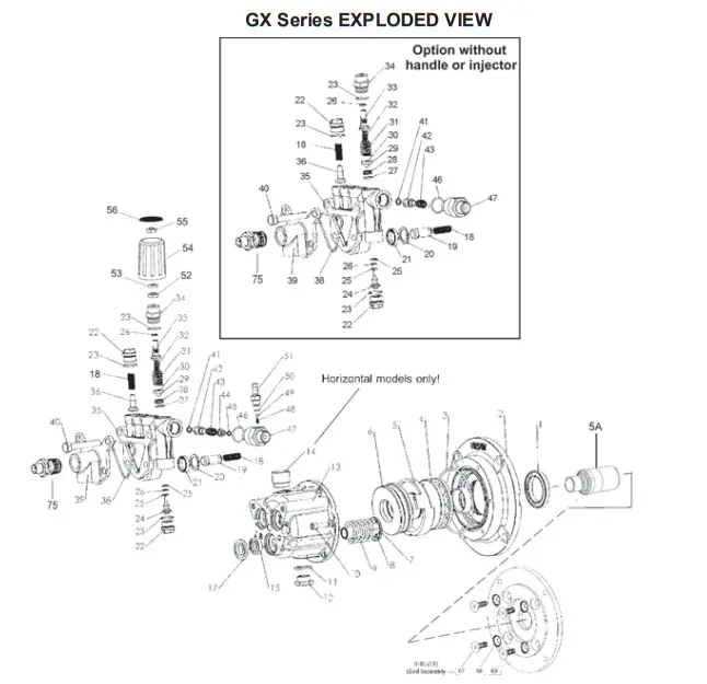
GX Series EXPLODED VIEW
Plunger Packing Kit
# 09465
| Item | Part # | Description | Qty. |
| 20 | 06290 | Support Ring | 3 |
| 21 | 06315 | V-Sleeve | 3 |
Valve Assembly Kit
# 09466
| Item | Part # | Description | Qty. |
| 18 | 07374 | Valve Spring | 6 |
| 19 | 06267 | Guided P-Valve | 3 |
| 36 | 06295 | Discharge Valve Cone | 3 |
Oil Seal Kit
# 09468
| Item | Part # | Description | Qty |
| 15 | 06316 | Plunger Oil Seal | 3 |
Unloader Repair Kit
# 09467
| Item | Part # | Description | Qty. |
| 23 | 12007 | O-Ring | 2 |
| 25 | 12031-0002 | Back-up Ring | 2 |
| 26 | 07937 | O-Ring | 2 |
| 27 | 08638 | O-Ring | 1 |
| 28 | 06256 | Seat | 1 |
| 29 | 06227 | 8mm Ball | 1 |
| 41 | 12326 | O-Ring | 1 |
REPAIR INSTRUCTIONS – GX SERIES
- With a 14mm socket wrench, remove the three discharge valve plugs (22). Inspect the valve plug o-rings (23) for wear, and replace as necessary.

- Remove the valve spring (18) and valve cone (36) from the manifold (35). Inspect the parts for wear and replace as necessary.

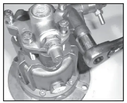
- With a crescent wrench, remove the kickback valve spring retainer (47). Inspect the o-ring (46) for wear and replace as necessary. Remove the kickback valve spring (43), kickback valve cone (42), and the o-ring (41) from the manifold (35). Inspect the parts for wear and replace as necessary.

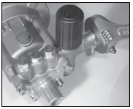
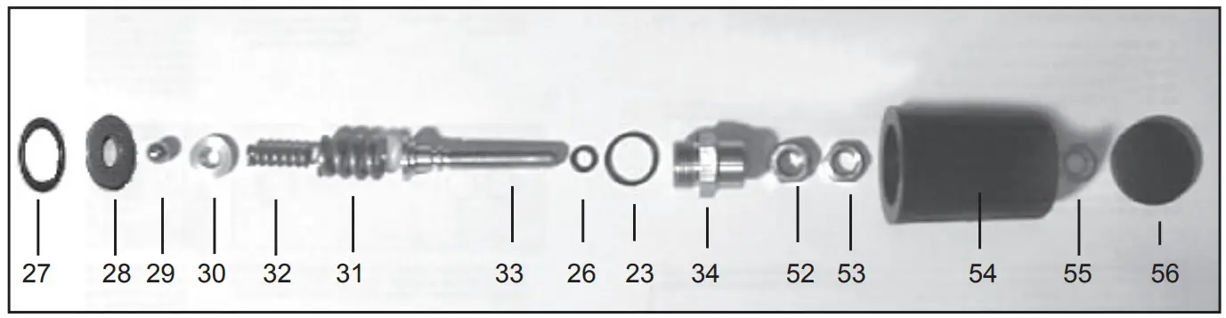
- With a 19mm wrench, remove the adjusting screw plug (34). Unscrew the adjusting screw (33) from the adjusting screw plug (34). Inspect the o-rings (23 & 26) for wear and replace as necessary
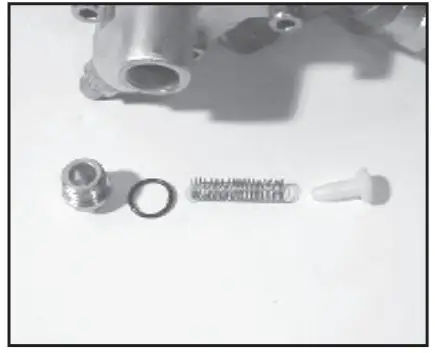
- Remove the adjusting spring (31), pressure spring (32), washer (30), and bypass valve ball (29) from the manifold (35). Inspect the parts for wear and replace as necessary.
Optional pump without handle – exclude items (52, 53, 54, 55, 56).
- With a 14mm socket wrench, remove the guide plug (22) and o-ring (23).

Remove the piston (24), o-ring (26), and backup rings (25). Remove the bypass valve seat (28). Inspect the parts for wear and replace as necessary. IMPORTANT! Make sure that the shoulder on the bypass valve seat (28) is facing the discharge plug (22).
 GX2525 EXPLODED VIEW
- Next, remove the four manifold bolts (40) with a 6mm Allen wrench.

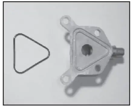
- Remove the suction flange (39) and flange O-ring (38). Inspect the o-ring for wear and replace it as necessary.

- Tap the back of the manifold (35) with a rubber mallet to dislodge, and slide off the plungers. (8). Take note of the position of the discharge port so as to place the manifold in the same position during reassembly
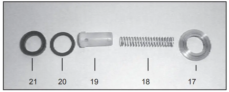
- Remove the guided p-valve, (19), valve springs (18), sleeves (21), and pressure rings (20). Inspect for wear and replace as necessary. Remove the spacer ring (17) from the lungers (8).

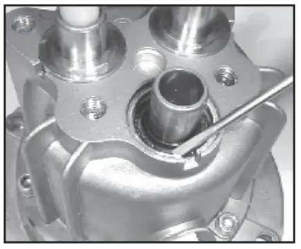
If the crankcase oil seals (15) are to be replaced, they can be removed by prying loose with a screwdriver. Take care not to make contact with the plunger (8) and pry out the oil seals from their housing. Seals should not be reinstalled until after step #13

Reassemble in reverse order. Fill the crankcase with the proper amount of oil (see specifications page 3). The pump is now ready for operation.

 GX2525 EXPLODED VIEW
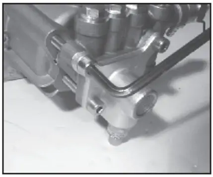
GX and HR Pump Part Numbering System
| GX or HR Series | Flow | Pressure (in 100 psi increments) | Injector Size | Thermal Relief Valve | Wobble Plate Shaft Bore | |
| Vertical | 20=GPM | 25=2500 PSI | 1=2.1 mm | 1=1/2″ | 2=7/8″ | |
| Horizontal | 23=GPM | 2=1.8mm | 1=3/4″ | |||
| 25=GPM | 3=2.3mm | 3=1″ | ||||
| 4=5/8″ | ||||||
| GX or HR | 2.5 | 25 | – | 1 | 1 | 1 |
For example, a GXV2525-112 is a GX pump that produces 2.5 GPM @ 2500 PSI, has an injector with a 2.1mm Orifice, 1/2” thermal relief valve, and 7/8” wobble plate bore.
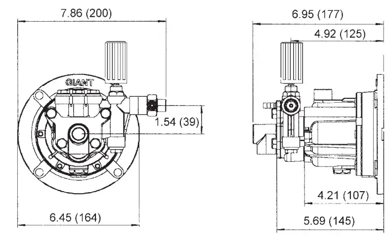
GX Series Dimensions inches (mm)
GIANT INDUSTRIES LIMITED WARRANTY
Giant Industries, Inc. pumps and accessories are warranted by the manufacturer to be free from defects in workmanship and material as follows:
- For portable pressure washers and self-service car wash applications, the discharge manifolds are guaranteed for the life of the pump. Our other pump parts, used in portable pressure washers and in-car wash applications, are warranted for five years from the date of shipment for all pumps used in NON-SALINE, clean water applica
- One (1) year from the date of shipment for all other Giant industrial and consumer
- Six (6) months from the date of shipment for all rebuilt pumps.
- Ninety (90) days from the date of shipment for all Giant accessories.
This warranty is limited to repair or replacement of pumps and accessories of which the manufacturers evaluation shows were defective at the time of shipment by the manufacturer. The following items are NOT covered or will void the warranty:
- Defects caused by negligence or fault of the buyer or third party.
- Normal wear and tear to standard wear parts.
- Use of repair parts other than those manufactured or authorized by Giant.
- Improper use of the product as a component part.
- Changes or modifications made by the customer or third party.
- The operation of pumps and or accessories exceeding the specifications set forth in the Operations Manuals provided by Giant Industries, Inc.
Liability under this warranty is on all non-wear parts and limited to the replacement or repair of those products returned freight prepaid to Giant Industries which are deemed to be defective due to workmanship or failure of the material. A Returned Goods Authorization (R.G.A.) number and completed warranty evaluation form is required prior for the return to Giant Industries of all products under warranty consideration. Call (419)-531-4600 or fax (419)-531-6836 to obtain an R.G.A. number.
Repair or replacement of defective products as provided is the sole and exclusive remedy provided hereunder and the MANUFACTURER SHALL NOT BE LIABLE FOR FURTHER LOSS, DAMAGES, OR EXPENSES, INCLUDING INCIDENTAL AND CONSEQUENTIAL DAMAGES DIRECTLY OR INDIRECTLY ARISING FROM THE SALE OR USE OF THIS PRODUCT.
THE LIMITED WARRANTY SET FORTH HEREIN IS IN LIEU OF ALL OTHER WARRANTIES OR REPRESENTATION, EXPRESS OR IMPLIED, INCLUDING WITHOUT LIMITATION ANY WARRANTIES OR MERCHANTABILITY OR FITNESS FOR A PARTICULAR PURPOSE, AND ALL SUCH WARRANTIES ARE HEREBY DISCLAIMED AND EXCLUDED BY THE MANUFACTURER.
![]()
Performance Under Pressure

Updated 12/16
GIANT INDUSTRIES, INC., 900 N. Westwood Ave., Toledo, Ohio 43607
PHONE (419) 531-4600, FAX (419) 531-6836, www.giantpumps.com
© Copyright 2016 Giant Industries, Inc.
12/16 GX2525.indd


