PALDRA Karman Vortex Flow Switch Instruction Manual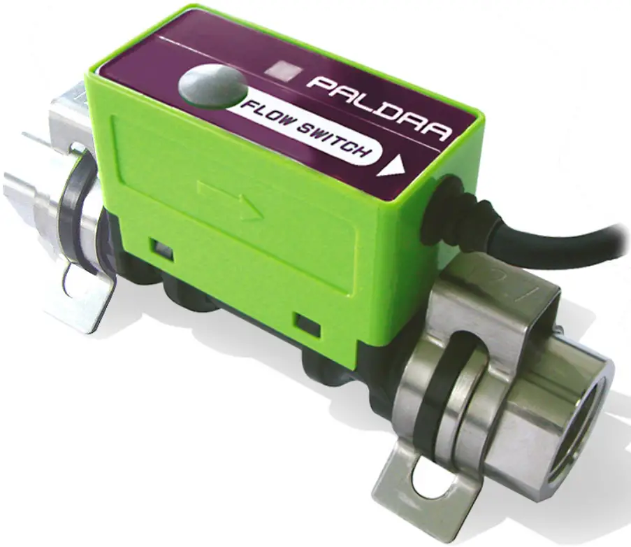
Features
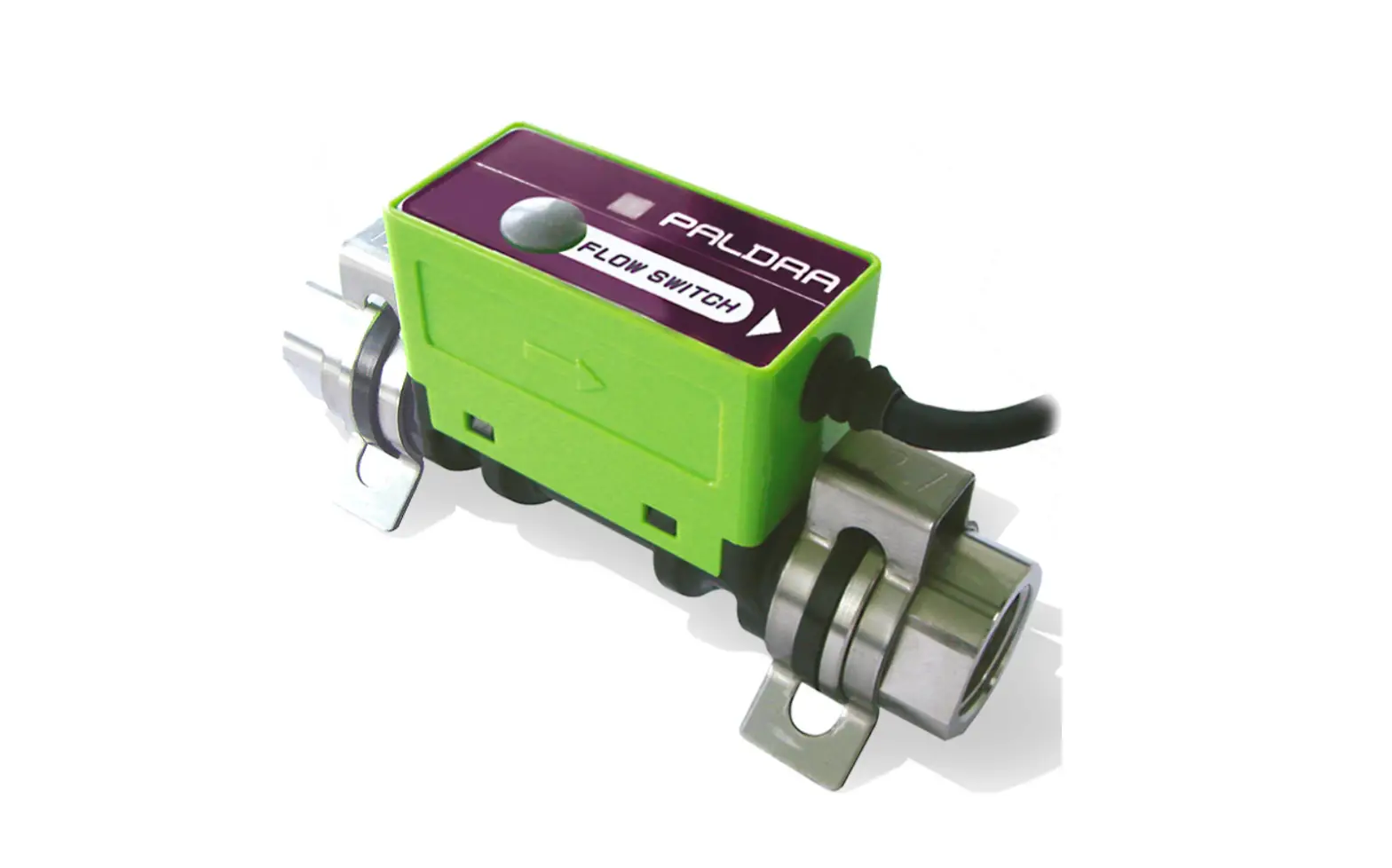
Karman vortex flow switch JPSW-5L/10L/30L is the new series of flow switch to measure flow rate, with simple functions and reasonable price. LED turns red from green if flow deviates from the set value Due to compact construction it can be installed in narrow space and simple structure resulting easy maintenance, easy installation and de-installation.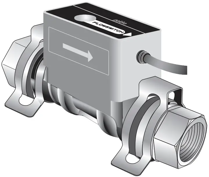
Before using our product
- Please read carefully the instructions before you use our product.
- Please follow the procedures, conditions and cautions as per the instructions.
Safety information
![]() Warning
Warning
Mishandling could cause injury or even death at drastic conditions
![]() Caution
Caution
Mishandling could cause disability, fire or other damages to the building or properties.
![]() Never do it.
Never do it.
![]() Do it only with following instructions.
Do it only with following instructions.
![]() Warning
Warning
Unusual or faulty conditions
![]() If you continue using our product under the unusual or faulty connections or conditions like as smoking, foul smell, unstable and malfunction, it could cause fire or accident. Cut the power supply immediately and contact to us. Do not try to repair the product yourself.
If you continue using our product under the unusual or faulty connections or conditions like as smoking, foul smell, unstable and malfunction, it could cause fire or accident. Cut the power supply immediately and contact to us. Do not try to repair the product yourself.
Working environments
| In the humid or dewing environment, it could cause accident or damage because of moisture. |
| In the vibration, impulsion or pulsation environment, it could cause malfunction, some accident or damage. |
| Our products are NOT explosion-proof. Do not use in the dangerous environment with flammable, explosive, or corrosive gas. |
| Do not use outside. This product is only for inside. |
| Installation in high temperature environment as near to heat instruments could cause some accident or damage as the heat instrument will led the temp rise inside the flow meter. Please use our product as instructed in the manual. |


![]() Caution
Caution
Cables
![]() Please do not put heavy objects on the cables or pull the cables from flow meter body, it could cause accident or damage.
Please do not put heavy objects on the cables or pull the cables from flow meter body, it could cause accident or damage.![]() Please follow the Instructions for “wiring”, “Output signal “other wise, it could cause accident or damages.
Please follow the Instructions for “wiring”, “Output signal “other wise, it could cause accident or damages.
Working environments
![]() Magnetic power, electromagnetic wave, radioactive ray or ultraviolet rays could cause accident or damage.
Magnetic power, electromagnetic wave, radioactive ray or ultraviolet rays could cause accident or damage.![]() Electric corrosion or static electricity could cause accident or damages.
Electric corrosion or static electricity could cause accident or damages.![]() In electrically noisy environments as like around high-frequency power source could cause accident or damages.
In electrically noisy environments as like around high-frequency power source could cause accident or damages.![]() Install the filter upper flow/Inlet to clear some piece of metal or small objects if needed.
Install the filter upper flow/Inlet to clear some piece of metal or small objects if needed.![]() Remove the bubbles in the fluid for accurate measurement of flow rate.
Remove the bubbles in the fluid for accurate measurement of flow rate.
Packaging and carrying
![]() Do not drop ,Handle with care otherwise The flow meter could damage or cause malfunctioning.
Do not drop ,Handle with care otherwise The flow meter could damage or cause malfunctioning.
Installations
![]() Mind your fingers while plumbing a sensor or you could get injured.
Mind your fingers while plumbing a sensor or you could get injured.
Maintenance
![]() Contact us for overhauling, adjusting or repairing. Please make sure not to touch an electronic substrate inside of flow meter.
Contact us for overhauling, adjusting or repairing. Please make sure not to touch an electronic substrate inside of flow meter.![]() Only a person who has technical knowledge and experiences could do plumbing, wiring, maintenance or overhauling.
Only a person who has technical knowledge and experiences could do plumbing, wiring, maintenance or overhauling.![]() while installation or maintenance please shut off the power and water supply for your safety.
while installation or maintenance please shut off the power and water supply for your safety.
![]() Others
Others
![]() Please contact us if you received damaged or deformed product.
Please contact us if you received damaged or deformed product.
Configuration and Dimensions
The electric circuit, substrate, is attached on a wetted part of the body which is covered with a cover. You find a rotary switch inside the cover, and a cables for interface on the side.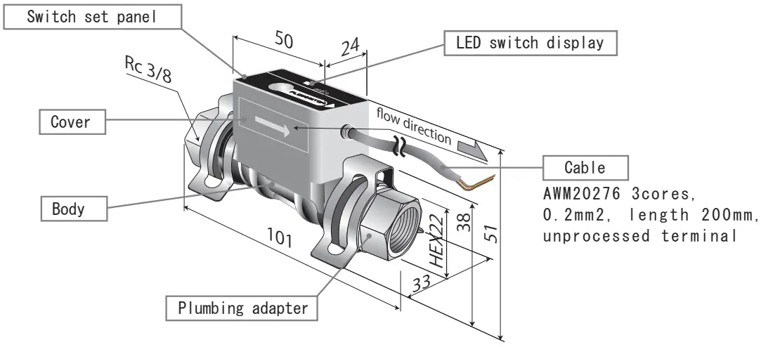
Specifications
This is the basic specification for JPSW. Please read them carefully for safe use.
| Models | JPSW-5L | JPSW-10 L | JPSW-30L | |
| Rated flow range | 0.5~5.0L /min | 1.5~10.0L /min | 5.0~30.0L /min | |
| Fluid | Industrial water, water | |||
| Detecting method | Karman vortex | |||
| Fluid temperature | 0~90℃ (No freezing ,no dewing) | |||
| Ambient temperature | 0~50℃ (No freezing ,no dewing) | |||
| Maximum working pressure | 1.0MPa | |||
| Withstanding pressure | 1.5MPa (at 20℃) | |||
| Pressure loss (at the maximum flow rate) | 46kPa | 60kPa | 85kPa | |
| Responsivity | Sampling0.5s | |||
| 1 power supply | DC24V±10% | |||
| Current consumption | MAX 20mA | |||
| 2 Switch output | Maximum load current | Max. DC 100mA | ||
| Maximum applied voltage | Max. DC 40V | |||
| Output mode | A output | |||
| 3 Display | 2colors LED | |||
| Certification, regulation | RoHS | |||
| Wetted material | Body PPS, FKM Adapter SUS304 | |||
| Adapter size | Rc3/8″ Quick fitting | |||
| Weight | 155g | |||
- 1 Voltage more than specified on the table will damage the product.
- 2 Default setting of switch is 0 memory (0L/min)at the time of shipment.
(Red LED will be on when there is no water flow) - 3 GRN: Flow rate > Set value RED: Flow rate < Set value
Wiring (interface)
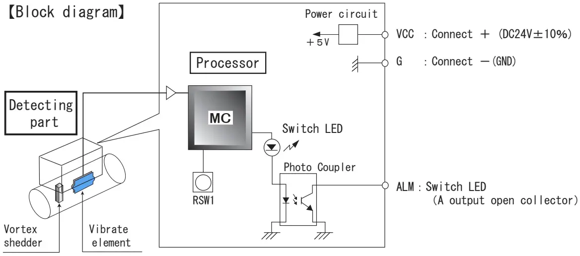
【Cable functions】
| Sign | Color | Name | Direction | Characteristic | Output selection | Operation and usage |
| CC | Red | Connect+ | DC24V±10% | Connect +side of power supply. Supply +24V to JPSW. | ||
| G | Black | Connect- |
| Connect -side of power supply. It is GND(0V) of JPSW. | ||
| ALM | White | Switch output | Photo Coupler( A ) | Alarming signal to equipment. (A) flow rate ≧ alarm value : ON flow rate < alarm value : OFF |
When setting 0L/min, it will be OFF ON, not in the water flow in the water flow detection.
Output signal
Switch output
The diagram below shows how to put a load of switch output. There is no polar character within the range in rating voltage or current.
Photo Coupler output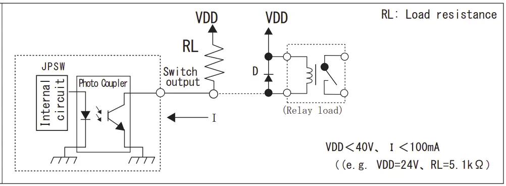
![]() Caution
Caution
Use relay with internal diode or external diode(D) to prevent damaging Photo Coupler from back electromotive force as above when you use relay load.
E.g. V03C(HITACHI)
Procedures
The diagram below shows a control panel on the top of the body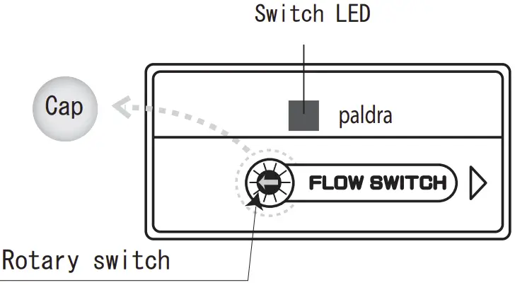
- Take off the cap
- Set the value with rotary switch
- LED light confirms the Deviation from set value.
【Power on】
This equipment does not have a switch to power on.
Connect a red wire,+V and black wire,0V with 24V then it starts to measure.
Alarm outputs and LED will be on.
Switch settings
Table: Explains definition of switch output and LED.
witch output and LED
| Switch Measuring value | A |
| More than set value | GRN ON ON |
| Less than set value | RED ON OFF |
A internal circuit of switch output is Photo Coupler. ON: conduction and OFF:
No conduction
![]() Do not use metallic screw driver to rotate or press to set. Use a insulating material, for example a plastic screw driver.
Do not use metallic screw driver to rotate or press to set. Use a insulating material, for example a plastic screw driver.
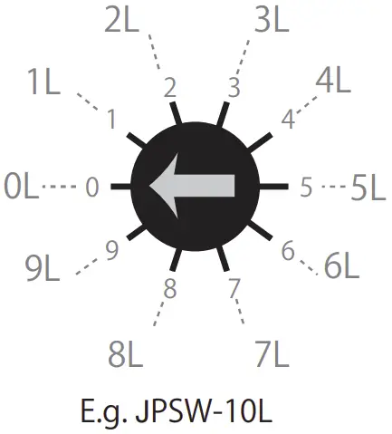
Indication of divisions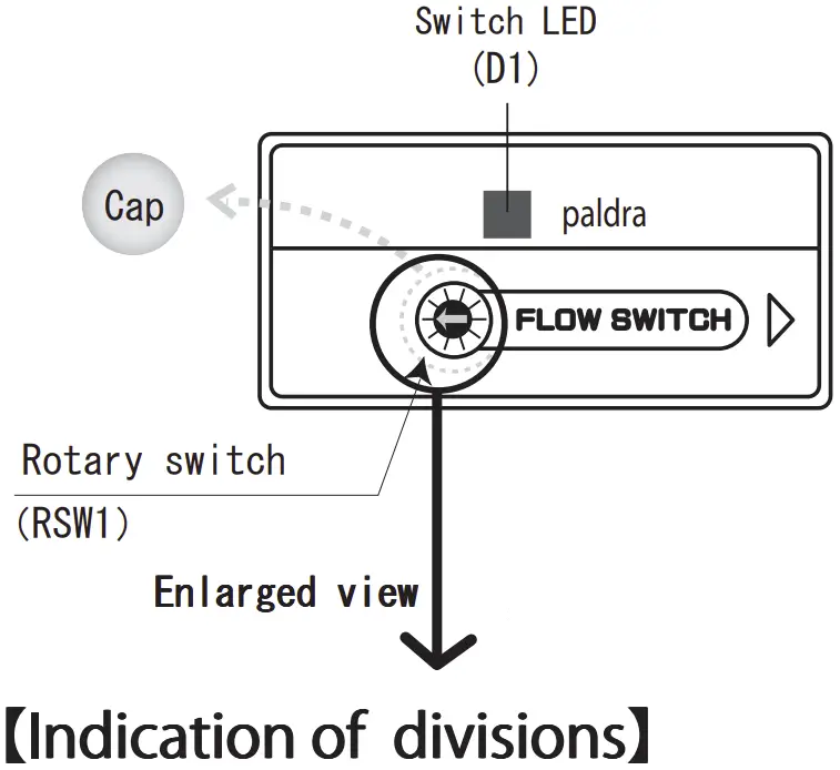
Point the arrow towards the setting value
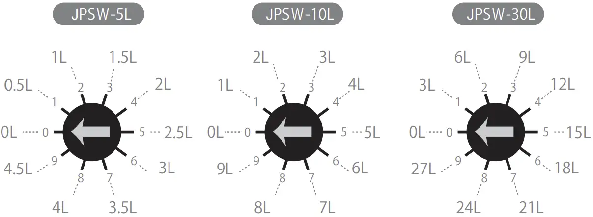
Flow rate set value diagram
| Memory switch Range type | 0 | 1 | 2 | 3 | 4 | 5 | 6 | 7 | 8 | 9 |
| JPSW-5L | 0 | 0.5 | 1 | 1.5 | 2 | 2.5 | 3 | 3.5 | 4 | 4.5 |
| JPSW-10L | 0 | 1 | 2 | 3 | 4 | 5 | 6 | 7 | 8 | 9 |
| JPSW-30L | 0 | 3 | 6 | 9 | 12 | 15 | 18 | 21 | 24 | 27 |
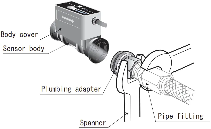
Connections
At the time of shipment adapters and quick fastener has enclosed separately.
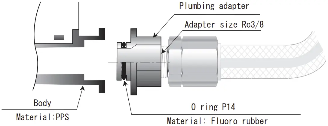
- Adapter is Rc3/8 female. Keep the adapter hold and screw the fitting.

 When you install our product between the hard plumbing, use hose or flexible tube to keep the center core straight.
 - Insert an adapter into a body. There is O ring, P14, around the adapter. Please pay attention to attach properly with no any particle in between.

- Put quick fastener on the adapter until the adapters are locked between the gap of the fastener. Make sure it is tightly locked.

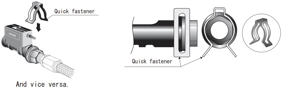
And vice versa
- A straight pipe length needs min. 7D on upper stream and 5D on down stream to keep the accuracy.
- Please do not do the plumbing (Put and orifice) sudden changes in the size of piping upstream.
- Install valves, bifurcations, gages etc. on down stream.
D=adapter size, 5L: 4.1mm, 10L: 5.8mm, 30L: 10mm - Please beware of the direct load/pressure on the flow meter (PPS). It could cause leaking or damages.
- Do NOT grab or press the cover very hard when you are connecting(plumbing)
Storage
Please store our products under environments as follows.
- Where it is NOT exposed to rain or water.
- Where it is NOT exposed to direct sunshine.
- Where it is NOT exposed to dust.
- Where it is NO vibration or impact.
- Where it is static-free.
- Where ambient environment is controlled between 0-50 degree Celsius without dewing and freezing.
Please store our products as you received.
Warranty and disclaimer
We are not responsible regarding the accident that occurred from the incorrect use of our products or possible lack of information in this document.
- Warranty period of our product is one year from the received date of the product(s).
- If the claimed defect of specifications or materials in the period of the warranty are verified with a document, we will replace free of the product(s). This warranty covers only our products. This warranty does not cover direct or/and indirect damages like lost, damages or injurers etc. caused by defected products.
- We supply a replacement on request. And an inspection of the equipment does not disclose any defect causing by us, the replacement will be charged.
- The replacement is the same product as we sold but we would supply a different
product for certain reasons. - It refers the case which we do not have any responsibility.
- The replacement is the same product as we sold but we would supply a different
- In use out of non-compliance regarding this instruction manual.
- Negligence in use.
- Dissembling or conversion of our products.
About instructions manual
- It is not allowed to reprint or reproduce a part or full instruction manual without any prior permission by us.
- All the contents of instruction manual are correct at the date of publication and are subjected to change without notice. Please save the latest issue of our products.
- The contents of the outline and specification of the flow sensor in this operating manual has followed as per the standards. Care must be carried out properly while using sensor with a proper lay-out and consideration against external condition.
- Please contact us if you acknowledge any mistakes or unlisted information in this instruction manual.
The design, dimensions and specifications of the product in the catalog were correct at the date of publication and are subjected to change without notice.


